The die failure prediction and prevention of the orbital
forging process
J.J. Sheu
∗, C.H. Yu
1Department of Mold and Die Engineering, National Kaohsiung University of Applied Sciences, Kaohsiung 807, Taiwan
a r t i c l e
i n f o
Keywords:
Orbital forging Die stress analysis Die failure Preform design
a b s t r a c t
The die failure occurs if the stress is too large. In this paper, the die stress analysis of the orbital forging process had been carried out to obtain the die stress distributions and predict the die failure. The different installation positions of punch, preforms, and profiles of punch tip and tool configurations were proposed to find the die failure conditions. The results of this study showed the installation error, punch tip with long mandrel and split die configuration had resulted in significant die stress and die failure occurred. The new punch profile and preform shapes had been designed to prevent the die failure and product defects. FEM code had been adopted to simulate the forging process and analyze the die stress. The upsetting tests had been carried out to obtain the flow stress parameters of AISI 4115. A PXW-200 orbital forging press had been adopted for the orbital forging tests. The failures of punch were observed in the experimental tests and precisely predicted by the simulation.
© 2007 Elsevier B.V. All rights reserved.
1.
Introduction
The near net shape forming and net shape forming of the gear parts had been wildly used in the modern industry (Dean, 2000) to increase the accuracy of product geometry. The char-acteristics of continuous flow lines of a forged gear improve the strength and the service life of products (Behrens et al.,
2007). A divided flow method was proposed to forge a ring
gear and avoid forging defects (Kondo and Ohga, 1995). The inward and outward material flows were controlled care-fully to achieve the die filling purpose. The alternative die design method was proposed for the net shape gear forg-ing. The die filling is improved by the auxiliary movement of die (Cai et al., 2004). The different punch profiles had been designed to improve the die filling quality of spur gear forging (Hu et al., 2007). The FEM method had been adopted to pre-dict the forming process and validate the results of different
∗Corresponding author. Tel.: +886 7 3494880; fax: +886 7 345 1401.
E-mail addresses:jjsheu@cc.kuas.edu.tw(J.J. Sheu),xian88999@yahoo.com.tw(C.H. Yu).
1 Graduate student.
designs (Li et al., 2001). The FEM method had been adopted to simulate the symmetric orbital forging processes success-fully (Liu et al., 2004). The defects and characteristics of the orbital forging process had been predicted precisely. The stress ring had been designed to increase the die strength for the spur gear forging (Kang et al., 2007). In this paper, different punch profiles and die configurations have been proposed and studied.
2.
Orbital forging process and simulation
models
The motions of an orbital forging press are differ to the con-ventional forging press. The punch rotates with respect to its central axis and the vertical axis of the press simulta-neously. The workpiece will be formed at the contact area locally.
0924-0136/$ – see front matter © 2007 Elsevier B.V. All rights reserved. doi:10.1016/j.jmatprotec.2007.11.178
Fig. 1 – Geometry and dimension of the ring gear part.
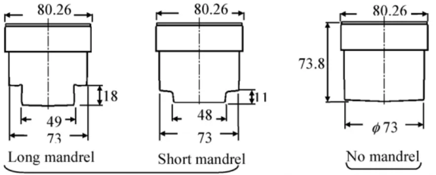
Fig. 2 – The different types of punch profile design.
2.1. Characteristics of the forged part
The geometry and dimension of the ring gear part of
material AISI4115 are shown in Fig. 1. Preform designs
are necessary to control the material flow and prevent forming defects for such a complex hollow product. The cold orbital forging process with lubrication had been adopted for the finish forming in this study. The billet had been fully annealed after the performing and piercing operations.
2.2. Preform designs, punch profiles and die configurations
Two types of hollow preform design were proposed to cope with the different punch profiles. The outer diameters are both 69.7 mm, while the inner diameters are 49 and 29 mm, respec-tively. Three types of punch profile are proposed and shown in
Fig. 2with the different length of mandrel. The solid and split die inserts were designed to study the influence of different
die configuration. There are three types of tool design combi-nation, design 1 uses punch with long mandrel and split die inserts, design 2 uses punch with short mandrel and solid die inserts, design 3 uses punch without mandrel and solid die. The preform design of larger inner diameter was used only in design 3.
2.3. Numerical simulations and experimental setups The FEM code, DEFORM 3D, was adopted for the numer-ical simulation. The flow stress of workpiece AISI4115 is modelled as a power law. The strength coefficient and the exponent of work hardness are 706.2 MPa and 0.245, respec-tively. The angular velocity of punch is 10.47 rad per second; the translation speed of die is 1.25 mm per second and stopped after 1.7 mm upward movement. The Coulomb and the con-stant shear friction models are adopted for punch and other tools, respectively. The friction coefficients of punch and the other tools are 0.06 and 0.12, respectively. A PXW-200 orbital forging press of 200-tonnes was adopted for the
Fig. 4 – The load distributions of correct (left) and incorrect (right) adjustments.
tal tests. The PXW-200 press and the control system are shown inFig. 3. The motion type of orbital press is circu-lar mode. The inclination angle of punch is 2◦. The feed of die is 0.9 mm per revolution with the rotational speed of 100 rpm.
3.
Results and discussion
3.1. Effect of the adjustment error of punch—with short mandrel punch design
The effects of the adjustment error were studied using the punch profile with short mandrel (type 2 of die design). The location of punch was shifted 2 mm downward with respect to the correct installation position. The predicted punch axial
punch, the load, and the velocity distributions are compared inFig. 5. The fractured surface of punch demonstrates a char-acteristic of torsional shear failure. The instantaneous velocity distribution of punch demonstrates an irregular shear defor-mation.
3.2. Results of the different tool and preform designs
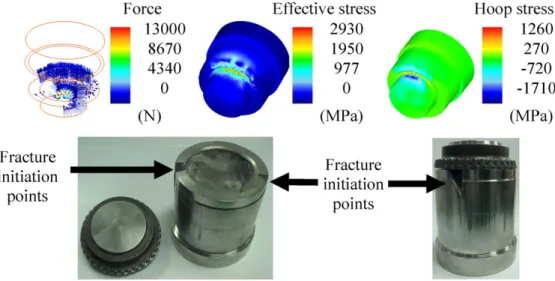
3.2.1. Type 1 of die design—punch with long mandrel The force and stress distributions of punch are shown inFig. 6. It demonstrates the local contact characteristic of the orbital forging process. The maximum effective stress and hoop stress of punch in tool design one are 2930 and−1710 MPa, respectively. The maximum effective stress of upper die insert is 1470 MPa. The maximum stresses of punch are very high and exceed the yield stress of SKD 11 (about 1600 MPa). As a result, the punch was fractured immediately. The simulation results show the concentrated high stress levels at the contact areas of punch shoulder. The picture of the fractured punch
Fig. 5 – The fractured punch surface, the force and velocity distributions.
Fig. 7 – The force, stresses and folding defects of design three.
Fig. 8 – The predicted force, stresses distribution, deformation and the experimental result.
also demonstrates the failure is initiated from the local high stress regions.
3.2.2. Type 2 of die design—punch with short mandrel The length of mandrel was shortened to reduce the rotational constraint and torsional stress of punch. The maximum effec-tive stress, radial stress, and hoop stress of punch are 1720, −1620 and −1260, respectively. These stresses are smaller than the results of design one while still higher than the yield stress of SKD 11. It is very obvious that the experimental tests will have the same results as design one.
3.2.3. Type 3 of die design—punch profile without mandrel The effective stress of punches with mandrel design is very high. A new punch profile without mandrel was proposed to reduce stresses. The simulation and the experiment results of step-by-step forging are shown inFig. 7to observe the material flow. The folding defects appeared on the hub surface due to the buckling of thin preform design in the forging process.
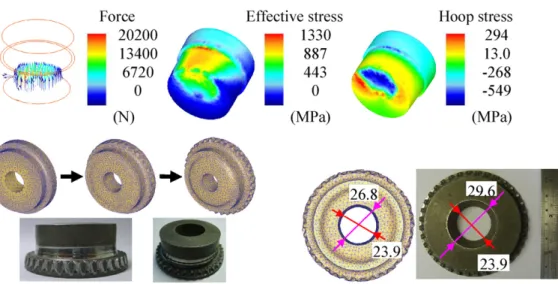
A new preform design with smaller inner diameter is pro-posed to solve the folding defects of product. The predicted stresses of tools are lower than the yield stress of SKD 11 and the failure of punch can be prevented. The force, effec-tive stress and hoop stress distributions of punch are shown inFig. 8. The contact area is increased and the stresses of tools are decreased dramatically. The forming process of the simulations and the experimental results are also shown in
Fig. 8. The inward flow of the new preform design can not only
decrease the tool stresses but also prevent the folding defects. The predicted inner diameters of top and bottom surfaces are 26.8 and 23.9 mm, respectively. The prediction results are in good agreement with the experimental measurements, 29.6 and 23.9 mm, respectively.
3.3. Tool design with prestressed ring—increase of tool life
The die insert can be designed with a prestressed ring to reduce stress level at forging process. The maximum effec-tive stresses of design 1, 2, and 3 without ring design are 1470, 1280 and 901 MPa, respectively. When a prestressed ring with 0.1 mm interference was adopted, the maximum effec-tive stresses of design 1, 2, and 3 are 1190, 1250 and 735 MPa, respectively. The maximum stress levels are decreased. The maximum effective stresses of design 1, 2, and 3 are increased to 1340, 1340, and 892 MPa, respectively with increasing the interference to 0.2 mm. It reveals that the proper amount of interference is crucial to reduce the maximum stress level.
4.
Conclusions
The effect of tool adjustment had been studied and is very crucial to the fracture of tools. The split die is good for man-ufacturing but the die stress is also increased. The punch profiles with mandrel design are capable of controlling the
of orbital forging process.
Acknowledgements
Financial support for this work was provided by the National Science Council Taiwan, ROC, under the contract NSC 95-2622-E-151-016-CC3. The man power and facility support of the New Kailung Gear & Machinery Co., Ltd. are specially thanked.
r e f e r e n c e s
Behrens, B.A., Doege, E., Reinsch, S., Telkamp, K., Daehndel, H., Specker, A., 2007. Precision forging processes for high-duty
Technol. 187/188, 600–603.
Kang, J.H., Lee, K.O., Je, J.S., Kang, S.S., 2007. Spur gear forging tool manufacturing method considering elastic deformation due to shrink fitting. J. Mater. Process. Technol. 187/188, 14–18.
Kondo, K., Ohga, K., 1995. Precision cold die forging of a ring gear by divided flow method. Int. J. Mach. Tools Manuf. 35, 1105–1113.
Li, G., Jinn, J.T., Wu, W.T., Oh, S.I., 2001. Recent development and applications of three-dimensional finite element modeling in bulk forming processes. J. Mater. Process. Technol. 113, 40–45.
Liu, G., Zhang, L.B., Hu, X.L., Wang, Z.R., Wang, R.W., Huang, S.D., Tang, Q.B., 2004. Applications of numerical simulation to the analysis of bulk-forming processes-case studies. J. Mater. Process. Technol. 150, 54–61.