2-GHz-repetition-rate Resonant Cad@ for
the
Enhancement of Second Harmonic Generation
I
Tzu-Ming Liu, Cheng-Ta Yu, and Chi-Kuang Sun
Graduate Institute of Electro-Optical Engineering and Department of Electrical Engineering, National Taiwan University, Taipei 10617, TAIH'AiV
Phone : 886-2-23659703, FAX : 886-2-23677467, E-mail :~941002@ee.ntu.edu.h+~
Abstract: We report, for the first time, a 2-GHz-repetition-rate all-solid-state resonant cavity for the enhancement of second-harmonic-generation. Pwnped by a 500-mW Ti:sapphire laser with the same repetition-rate, 60-mW femtosecond pulses at 409nm can be generated.
0 2004 Optical Society of Amenca
OCIS codes: (140.341 0) Laser resonators, ( I 90.41 60) Multiharmonic generation, (320.71 60) Ultrafast technology
Gigahertz-repetition-rate femtosecond lasers open a wide range of applications. These lasers provide simultaneous multi-channel sources for the fiber communication,[ 11 high signal-to-noise ratio measurements, and frequency metrology.[2] For the study of coherent acoustic phonons, intense femtosecond blue-sources with a repetition rate 2 2 GHz are required for the generation of sustained acoustic phonon oscillations [3]. With its low pulse energy of a >2GHz repetition-rate femtosecond Ti:sapphire laser, the yield of the nonlinear second-harmonic-generation (SHG) is too low to meet the experimental requirement. Therefore, higher fundamental peak power is needed to raise the conversion efficiency without degrading the phase-matching bandwidth. In this paper, based on a LBO crystal, we report a 2-GHz-repetition-rate resonant cavity for the enhancement of SHG. After cascading the system after a 2-GHz-repetition-rate Tisapphire laser, high-energy femtosecond blue pulses with the same repetition-rate can be obtained.
Fig. 1.
PP
L l L2 2-GHz Repetition-rate Tisapphire Laser M I c1 c2.
servo F Electronics QWPn
D2Schematic diagram of the doubling cavity. M: folding mirror; L1, L2, mode-matching lenses; HWP, half-wave-plate; M1, PZT driven mirror; M2, input coupler; C1, C2, concave mirrors; F, neutral density filter (ND=5); QWP, quarter-wave plate; PBS, polarization beam splitter; D1, D2, photodiodes; DA, differential amplifier.
Figure 1 shows a schematic diagram of our experimental setup. A 2-GHz-repetition-rate femtosecond Ti:sapphire laser provides 500mW of 80-fs fundamental pulses at 816 nm with 34-nm bandwidth. A pair of lenses, Lland L2, was used to manipulate the q-parameter of the fundamental beam before the resonant cavity. The fundamental power was enhanced with a four-mirror ring cavity consisting of two flat mirrors, M1 and M 2
,
and two curve mirrors, C1 and C2, with 2.5-cm radius-of-curvature. M 2 served as an input coupler with 80% reflectivity. At the focus between C1 and C2, a Brewster cut LBO crystal with 0.5-mm thickness was chosen as the SHG material. The astigmatism compensation angle of curve mirrors was approximately 11" based on a calculation.[4] The generated SHG was output from C2, whose transmission was 66% at 409 nm. To achieve better mode matching between laser cavity and the SHG resonant cavity, the length of the resonant cavity (45cm) is chosen to be three times that of the pumping Ti:sapphire laser (1 5cm). This ratio is kept with the aid of the Hhsch-Couillaud method. [5] Following this technique, the error signal was generated with a depolarization
system and feedback to a PZT driver through servo electronics. Then the driver applied voltage on the PZT (300kHz resonant frequency) to move MI, which dynamically compensated the thermal and mechanical disturbance on the resonant cavity system and followed the disturbance in the laser system.
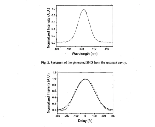
With the servo loop turned on, 60-mW average SHG can be obtained, corresponding to 18% conversion ef‘ficiency. The spectrum of the resonant SHG output is centered -409 nm with a 4-nm bandwidth (Fig. 2). A four-wave mixing based third-order correlator with an hGaN/GaN quantum well sample [6] shows a 200-fs pulse-width based on a Gaussian fit (Fig. 3). Detailed experimental condition and results will be discussed in the presentation.
Wavelength (nm)
Fig. 2. Spectrum of the generated SHG from the resonant cavity.
i . l . l . , . , . , . I -300 -200 -100 0 100 200 300
Delay (fs)
Fig. 3 Third-order correlation trace measured by non-degenerate four-wave mixing (open circles). Solid line is a Gaussian fit. References [ 13 [2] [3] [4] [ 5 ] [6]
L. Boivin, et.al., “206-channel chirped-pulse wavelength-division multiplexed transmitter,” Electron. R. Holzwarth, et al., “Optical frequency synthesizer for precision spectroscopy,” Phys. Rev. Lett. 85, C.-K. Sun, et al. “Coherent acoustic phonon oscillations in semiconductor multiple quantum wells with piezoelectric fields” Phys. Rev. Lett. 84, 179- 182 (2000)
H.W. Kogelnik, et al., “Astigmatically compensated cavities for CW dye lasers,” IEEE J. Quantum Electron. QE-8,373-379 (1972).
T.W. Hansch and B. Couillaud, “Laser frequency stabilization spectroscopy of a reflecting reference cavity”, Opt. Commun. 35,44 1-444 (1 980).
H. Schulz, et al., “Measurement of intense ultraviolet subpicosecond pulses using degenerate four-wave mixing,” IEEE J. Quantum Electron. 25,2580-2585 (1989).
Lett. 33,827-829 (1997). 2264-2261 (2000).