Journal of Neuroscience Methods 131 (2003) 107–110
A simple method for fabricating horizontal and vertical microwire arrays
Meng-Li Tsai
a,∗, Chen-Tung Yen
baDepartment of Biomachtronic Engineering, National I-Lan Institute of Technology, 1 Shen Lung Road, Sector 1, Ilan 260, Taiwan, ROC bDepartment of Zoology, National Taiwan University, Taipei, Taiwan, ROC
Received 20 April 2003; received in revised form 22 July 2003; accepted 24 July 2003
Abstract
Microwire array electrodes are important in multi-site, multiple single-unit recording experiments. A simple method is described herein for the construction of microwire arrays consisting of evenly spaced insulated microwires in either horizontal or vertical orientations. Several key steps in the fabrication of a good microwire array electrode are made easier with this method. These steps include (1) arranging microwires into a desirable configuration, (2) keeping track of microwire sequences, and (3) soldering microwires to closely packed slots. This method needs only general mechanical tools and is relatively simple even for inexperienced workers.
© 2003 Elsevier B.V. All rights reserved.
Keywords: Microwire array; Ensemble neuronal recording; Single-unit recording
1. Introduction
Microwire array electrodes of various configurations have been used for multi-site, multiple single-unit record-ing experiments (Eichenbaum and Davis, 1998; Nicolelis, 1998). For recording in conscious animals, 24 microwires in rats (Chapin et al., 1999) and 96 microwires in monkeys (Wessberg et al., 2000) are quite feasible. Multi-electrode arrays can be purchased from commercial vendors and are reliable for many experimental paradigms described in the literature (Fanselow et al., 2000; Laubach et al., 2000; Nicolelis et al., 1997; Wessberg et al., 2000). However, economic considerations and flexibility of the experimen-tal design still make it worthwhile to develop fabrication methods in-house.
In this paper, we describe a simple procedure, which uti-lizes only general mechanical tools. This procedure was de-signed to improve the following steps for the fabrication of microwire arrays: (1) arranging microwires to the de-sired configuration, (2) maintaining the corresponding se-quence of the microwires, especially in vertical bundle type electrodes, and (3) soldering the microwires to the closely packed slots of a headpiece connector. The procedure
de-∗Corresponding author. Tel.:+886-3-9357400x851;
fax:+886-3-9326345.
E-mail address: mltsai@ilantech.edu.tw (M.-L. Tsai).
scribed herein has been successfully used in many differ-ent configurations. It is relatively simple even for a novice worker to carry out.
2. Materials and methods
Two types of microwire arrays are described to illustrate the fabrication procedure: a 16-channel horizontal array and an 8-channel vertical array.
2.1. The 16-channel horizontal microwire array 2.1.1. Specifications
The microwire array consists of 16 Teflon-insulated mi-crowires (AM system, Carlsborg, WA; #790700) which are aligned in single file, with an inter-electrode separation of 400–500m for a total horizontal span of 8 mm. This type of microwire array is suitable for single-unit recording from a large brain region such as the primary sensorimotor cor-tex, the primary motor corcor-tex, and the occipital cortex in the rat (Yen et al., 2002).
2.1.2. Straightening the microwire
Commercially available microwires are usually spooled. Microwires cut from the spool are curved; thus, they are not suitable for the fabrication of electrode arrays. We 0165-0270/$ – see front matter © 2003 Elsevier B.V. All rights reserved.
108 M.-L. Tsai, C.-T. Yen / Journal of Neuroscience Methods 131 (2003) 107–110
straightened the curved microwires by means of spinning them. Spooled microwires were cut into 10 cm segments. A hemostat was clipped to each end of the curved microwires; the upper one was held while the lower end was gently allowed to spin until the microwires were straightened. The straightened microwires were cut into sixteen 3 cm seg-ments, and approximately 2 mm of insulation was removed from one end by touching it briefly to a small flame. 2.1.3. Arraying and soldering
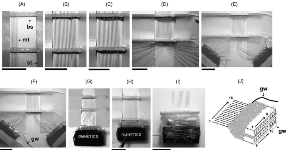
Two slim bamboo (or wood) sticks were fixed about 1 cm apart onto a piece of paper with sticky tape to serve as the fabrication jig. A razor blade was used to make notches in the bamboo sticks to mark the positions of the microwires. A small drop of epoxy glue was spread on the surface of the sticks, and the straightened microwires were placed into these notches before the glue solidified (Fig. 1A). Af-ter all the microwires were placed in their proper positions (Fig. 1B), another drop of epoxy glue was applied to the sticks to cover the wires (Fig. 1C). When the epoxy glue had solidified, the free ends of the microwires were bent to two groups (Fig. 1D). A 10-pin subminiature headpiece connec-tor (Omnetics Connecconnec-tor, Minneapolis, MN) was taped near one group end, and each microwire was inserted into the slot of the headpiece connector and soldered in turn (Fig. 1E). A stainless-steel ground wire was soldered to the final two slots. Soldering paste (for example, Taiyo Electric, Japan) was used to assist the soldering process. It is necessary to check all the microwires were soldered tightly for confirm-ing the electrical continuity. All solderconfirm-ing points were finally sealed and stabilized with a thin layer of epoxy (Fig. 1F).
Fig. 1. The fabricating procedures for the 16-channel horizontal microwire array. (A–I) indicates the key steps of the array’s fabrication; the details were described in the text; bs: bamboo stick; gw: grounding wire; mt: Teflon-insulated microwire; st: sticky tape. (J) Sketch of the finished product. A dashed circle indicates the channels for grounding. The calibration bars of (A–F), (H) and (I): 8 mm.
2.1.4. Assembly and formation
When all 16 microwires were successfully soldered to the two headpiece connectors, the tape on the connec-tors was removed, and these two connecconnec-tors were glued together using epoxy (Fig. 1G). After the epoxy had solid-ified, the combined headpiece connector set was pressed against the proximal bamboo stick as compactly as possible (Fig. 1H). The frontal plane of the headpiece connector set was adjusted so that it was perpendicular to the plane of the array, and then it was secured using adhesive tape. Epoxy glue was administrated to fill in any spaces be-tween the bamboo stick and the connector set. A piece of paraffin membrane was used to restrain the surplus wires in the gluing space and to minimize the volume of glue required. The connector set was cut from the jig after the epoxy had solidified. The array was turned over, and any loose spaces on the reverse side were filled in with epoxy glue. The recording tips of the microwires were further modified to the desired shape with a pair of sharp scissors (Fig. 1I).
The soldered connection between the microwire and the headpiece connector is the most frequent point of failure. The fixed connector and microwires in our design mini-mize vibration resulting from operation, which decreases the chance of spilling soldering tin into neighboring slots. If this occurs, the tin can be carefully scraped off with a thin knife. Do not attempt to melt the excess tin, as this often causes it to short additional slots. The soldered joint itself does not produce a very strong mechanical connec-tion, and it is important to entirely cover the joint with epoxy.
M.-L. Tsai, C.-T. Yen / Journal of Neuroscience Methods 131 (2003) 107–110 109
2.2. The eight-channel vertical microwire array 2.2.1. Specifications
A Teflon-insulated microwire (AM system, Carlsborg, WA; #790700) was used as the centerpiece and the ventral-most sensor. Seven formvar-insulated nichrome microwires (AM system, Carlsborg, WA; #761000) were arrayed spirally onto the centerpiece in sequence so that the inter-electrode separation was 250–350m for a total vertical span of about 2 mm. This type of microwire array is suitable for single-unit recording from different layers of the cerebral cortex.
2.2.2. Straightening the microwires
The Teflon-insulated microwires were straightened as described in the previous section. The formvar-insulated nichrome microwires were cut into 3 cm segments with-out straightening. The insulation from one end of each microwire was removed by briefly holding it in a flame. 2.2.3. Arraying and soldering
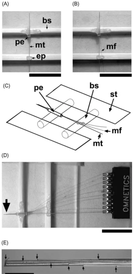
Two slim bamboo (or wood) sticks were fixed about 0.5–1 cm apart on a glass slide with sticky tape. A length of PE-50 tube (about 3 mm) was glued to the distal stick. The Teflon-insulated microwire was passed through the PE tube, and about 3 mm was exposed from the edge of the tube. A tiny drop of epoxy glue was used to fix the mi-crowire onto the proximal stick (Fig. 2A). When the epoxy glue had solidified, a formvar-insulated nichrome microwire was passed through the tube. A drop of water was used to temporarily hold these two microwires together. With the aid of a dissection microscope, the relative positions of the two tips were adjusted. When the nichrome wire was properly positioned, a tiny bead of epoxy was applied to a site near the edge of the PE tube to secure these two wires. The nichrome microwire was further secured about 1 mm from the fixed point of the Teflon-insulated microwire with a bit of epoxy on the proximal stick (Fig. 2B and C). The same procedure was repeated for the remaining nichrome microwires (Fig. 2D). The microwires were soldered to a headpiece connector as described in the previous section. All welded points and exposed metal parts were sealed and stabilized with a thin layer of epoxy. The final implant prod-uct was formed in a process similar to the one described in the previous section.
3. Performance and discussion
The microwire arrays described in this paper are easy to make. They offer the flexibility needed to tailor arrays to the desired parameters of a particular experiment. A repre-sentative example is shown inFig. 3and was reported in a preliminary form (Yen et al., 2002).
The most critical aspect of fabricating a microwire array involves the precise spacing of the electrode tips. Verloop
Fig. 2. Fabrication jig and the assembly of the eight-channel vertical microwire array. (A) Initial step of arraying, the Teflon-insulated microwire was passed through the PE tube. (B) The nichrome microwire was further secured about 1 mm from the fixed point of the Teflon-insulated microwire with a bit of epoxy on the proximal stick. (C) Sketch of the details of (B); bs: bamboo stick; gs: glass slide; mt: Teflon-insulated microwire; mf: formvar-insulated microwire; pt: PE-50 tube; st: sticky tape. (D) All the nichrome microwire were fixed on the stick. (E) The vertical arrayed tips (indicated by the arrows) of the recording end (indicated by a larger arrow in D). The calibration bars of (A), (B) and (D): 10 mm; (E): 0.5 mm.
and Holsheimer (1984)described a simple method for con-structing an array of parallel wire electrodes. They posi-tioned a number of wires in parallel at equal distances by using two springs made from wire with a diameter that equals the desired spacing between the electrodes.Williams et al. (1999)constructed a special fabrication jig in which the precise spacing could be achieved by draping the mi-crowires over fine musical instrument wire and placing them
110 M.-L. Tsai, C.-T. Yen / Journal of Neuroscience Methods 131 (2003) 107–110
Fig. 3. Superimposed spike waveforms of a multiple single-unit recording session. All waveforms were from the microwires (ch 1–16) of a 16-channel horizontal microwire array. Different colored waveforms indicate different single-unit activities. The microwire array was placed parasagittally along the right side of the cerebral cortex about 2–3 mm lateral to the midline and inserted 1.8 mm deep. This implantation recorded single-units activities of the hindpaw (ch 7–9) and tail (ch 10) regions in the primary sensorimotor cortex, the head and forelimb region in the primary motor cortex (ch 1–4), and the occipital cortex (ch 16) in the same rat. Bar: 0.5 ms.
individually into the instrument wire slots. In the present study, our architectural tactic provides greater flexibility for a variety of shapes and sizes. The area of the fabrication jig is small enough so that it can be placed under a dissect-ing microscope, and compact spacdissect-ing can more easily be achieved.
Another benefit of this jig is the ease by which the over-all size of the microwire arrays can be reduced. Moving the connector tighter against the proximal bamboo stick minimizes the distance between the electrode tips and the headpiece connector. With smaller electrode assemblies, less space on the animal’s skull is occupied, thus more implants can be used in one animal, and more neurons and brain structures can be monitored. Furthermore, the jig offers the advantage that the precise sequence of the microwires is maintained in the connector slots. This is very important when fabricating a microelectrode bun-dle for which the sequence of the microwires is usually lost.
Acknowledgements
This study was supported by the National Science Council, NSC91-2311-B002-017, and the National Health Research Institute, NHRI-EX90-9018EP.
References
Chapin JK, Moxon KA, Markowitz RS, Nicolelis MA. Real-time control of a robot arm using simultaneously recorded neurons in the motor cortex. Nat Neurosci 1999;2(7):664–70.
Eichenbaum HB, Davis JL. Neuronal ensembles: strategies for recording and decoding. 1st ed. New York: Wiley; 1998. p. 6–8.
Fanselow EE, Reid AP, Nicolelis MAL. Reduction of pentylenetetrazole-induced seizure activity in awake rats by seizure-triggered trigeminal nerve stimulation. J Neurosci 2000;20(21):8160–8.
Laubach M, Wessberg J, Nicolelis MAL. Cortical ensemble activity in-creasingly predicts behaviour outcomes during learning of a motor task. Nature 2000;405(6786):567–71.
Nicolelis MAL. Methods for neural ensemble recordings. 1st ed. Boca Raton, FL: CRC Press; 1998. p. 2–10.
Nicolelis MAL, Ghazanfar AA, Faggin B, Votaw S, Oliveira LMO. Re-constructing the engram: simultaneous multiple site, many single neu-ron recordings. Neuneu-ron 1997;18:529–37.
Verloop AJ, Holsheimer J. A simple method for the construction of electrode arrays. J Neurosci Meth 1984;11(3):173–8.
Wessberg J, Stambaugh CR, Kralik JD, Beck PD, Laubach M, Chapin JK, et al. Real-time prediction of hand trajectory by ensembles of cortical neurons in primates. Nature 2000;408(6810):361–5. Williams JC, Rennaker RL, Kipke DR. Long-term neural recording
char-acteristics of wire microelectrode arrays implanted in cerebral cortex. Brain Res Protocols 1999;4(3):303–13.
Yen CT, Tsai ML, Kuo CC, Lee JC. Cellular basis of laser heat-evoked cortical potential studied with neuronal ensemble recording. In: Pro-ceedings of the 32nd Annual Meeting on Society of Neuroscience, 2002.