Code Compression Architecture for Memory Bandwidth Optimization in Embedded Systems
6
0
0
全文
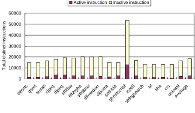
(2) The remainder of this paper is organized as follows. Section 2 describes some common issues of code compression and the solutions we pose. The overview of all components and system architecture of our work are introduced in Section 3. Section 4 first presents evaluation methodology and simulation environment then analyze the experimental results. Finally we summarize our contributions in Section 5.. 2. occurrence of the same instruction will be replaced by a shorter code word. As Luca et al. surveyed in [5], the static entropy of 10 embedded programs average smaller than 12 bits and use up to 14 bits of fixed encoding length. This means for program with K distinct instructions, log2(K) < 14 for all test program in [5]. Our analysis on MiBench [8] suite yields a slightly different result.. Code Compression Issues. Active instruction. Inactive instruction. 2.1 Compression Algorithm Traditional algorithm for data compression has focused on compression ratio which can be translated as the space saving by compression. Much of these algorithms can only decompress sequentially. (e.g. you have to decompress the whole text file in order to extract one paragraph) As the behavior of a program is surely non-sequential when branch instruction is taken, the algorithm must be able to decompress from any place of the compressed code rather than only from the beginning. Such random access behavior of program and the need to decompress on-the-fly make the well-know Ziv-Lempel family algorithms [6] futile. Dictionary-based algorithm inherently supports random access of compressed content since it does not depend on correlation of adjacent data to decode. Various code compression systems of dictionary-based scheme have been proposed in the literature [4, 5, 7] including CodePack[3]. Our design differs from previous works in that we try to reduce memory traffic while providing even better performance than original system. We suppose code compression can provide both memory traffic reduction and performance increment by exploiting the cache expansion property of post-cache architecture. Hardware simplicity and decompress efficiency are considered more important than compression ratio in our opinion. Therefore we devise our system using a 16-bits fixed-length encoding scheme of which reasons are stated as follows. Repetition of object code encoding is the theoretical basis of dictionary-based schemes. All the repeated. 50000 40000 30000 20000 10000. c un rc to A v as er t ag e. bf sh a. 0. bi tc nt s qs or su t sa n cj pe g dj pe tif g f2 tif bw f2 rg tif ba fd tif it he fm ed r i di an jk s pa tra gh tric os i a ts cr ip t st r in isp gs el l ea rc h. This section presents some common issues of code compression and the solutions we proposed to accommodate them. For a code compression system to function efficiently there would be some constraints on the compression algorithm chosen to implement. Another fundamental issue is the addressing problem of compressed code, since the addressing space is compressed with the code itself. Finally for a Harvard-architecture processor, some data access of load instructions will cause hazards. We name this kind of hazard as inline data access because it occurs when a load target lies inside the text section but not the data section. The following paragraphs will discuss the compression algorithm of our system and then present the techniques we employed to properly adjust fetch address and resolve the inline data hazard.. Total distinct instructions. 60000. Figure 2. Distinct Instruction Encoding Distribution Figure 2 shows the distinct instruction counts of 18 test programs from MiBench. Most testbenches have instructions below 20,000 and the ghostscript has more than 50,000 distinct instructions. At least 16 bits must be employed to encode all distinct instruction patterns. Another fact we can derived from Figure 2 is that, on average, only 15% of instructions produced by compiler (below 3,000 instructions) are active during program execution. This fact means only a small portion of the dictionary needs to be accessed by decompression hardware during program execution. If the dictionary is properly “cached” closed to the processor, the impact to fetch latency due to decompression overhead will be significantly diluted.. 2.2 Fetch Address Adjusting. Figure 3. Compressed Code and Address Space The compressed instructions occupy less space in memory than original ones as Figure 3 shows. The processor core must function correctly without knowing addressing space of a program is compressed. Therefore. - 237 -.
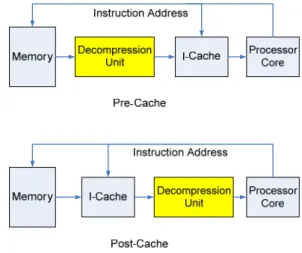
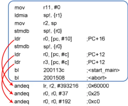
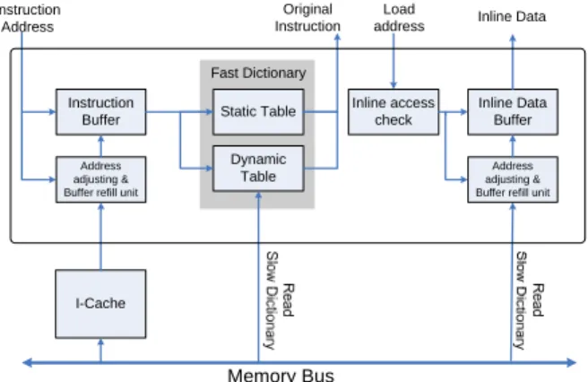
(3) the address generate from the fetch stage of processor must be intercepted and adjusted to proper access the compressed program. Wolfe and Chanin proposed an address translation scheme called LAT in [9]. LAT is a table much like paging table of virtual memory and needs an address translation buffer called CLB (which acts like TLB). Their scheme is capable of generating non-regular compressed addresses of variable-length code word systems such as CodePack. However LAT is dependent on size of cache line and only applicable in pre-cache architecture. The address adjusting for a fixed-length code word compression algorithm is much easier and can be implemented with simple combinatorial circuits as follow formula: compressed_address = base_address + (origin_address – base_address) × compress_ratio where base_address is the text section start address, origin_address is the address generated by processor and the compress_ratio equals to code word length divide by instruction length. (e.g. in our case, the compress_ratio = 16/32 = 0.5) Depending on different compress_ratio, the address generated from the equation may not be aligned to byte boundaries, and it might be necessary to apply additional bit masks to locate the code word.. it would be hazardous for processor to access theses data directly because load requests directly go to data cache which contains only other uncompressed data of program. An additional hardware comparator which checks the load request addresses is deployed to filter out inline data accesses. Those load requests with target address located in text section will be intercepted and perform address adjusting and decompression. Other load or store requests will be simply bypassed to data cache.. 3. System Architecture. Figure 5 provide an overview of our system. The components surrounded by dash line are hardware components. The colored blocks are data modified or components integrated due to code compression. A code compressor is developed to parse the original ELF file generated from GNU tool chain and compresses the text section of it. Note the data section is left uncompressed since in most cases the input to the program is unknown at compilation time. The new text section image generated by compressor contains the compressed instructions and the dictionary used to decode it. As previously mentioned the decompression unit is placed between processor and cache memories. The decompression unit shares the same main memory bus interface with cache system.. 2.3 Inline Data Access There are some data such as initial value of loop counter or stack base address often reside in the text section of binary image. These read-only values are often placed below the basic block boundaries where they can be loaded with small offsets relative to program counter as Figure 4 depicts. Such data embedded inside text section will be considered instructions and compressed like other instructions, so not only their addresses are shifted but also the actual values will be replaced by compressed code words. Figure 5. System Overview. 3.1 Decompression Unit. Figure 4.. Example ARM Assembly Code of Inline Data Access. The block diagram of decompression unit is depicted in Figure 6. An instruction buffer is used to hold multiple compressed code words of sequential addresses. Another buffer called “inline data buffer” holds the recently used inline data to eliminate inline access penalty. We adopted a fast dictionary similar to [5] for fast decompression, and further improved its structure by integrating a dynamic table in it. The intention of fast dictionary is to store the most frequently executed instructions near the processor for fast decompression.. It’s obvious these data will be filled into instruction caches with other instructions in compressed form. But. - 238 -.
(4) Original Instruction. Instruction Address. Load address. consecutive 16 bytes of compressed instructions for fast dictionary lookup. As mentioned the static table inside fast dictionary contains fixed entries of most frequently fetched instructions while the dynamic table collects the recently used ones. The contents of the two tables are exclusive to each other and a fast dictionary miss is generated when neither table contains the information to decompress. Upon a fast dictionary miss the slow dictionary will be accessed to retrieve original instruction and the dynamic table will be updated.. Inline Data. Fast Dictionary Instruction Buffer Address adjusting & Buffer refill unit. Static Table Dynamic Table. Inline access check. Inline Data Buffer Address adjusting & Buffer refill unit. I-Cache. Figure 6.. Load Address. Instruction Address. Memory Bus. Block Diagram of Decompression Unit. No. Instruction Buffer hit?. No. Inline Data Access?. Yes. Yes. Inline Data Buffer Hit?. Yes. Address Adjusting. No No. In the origin design, the contents of fast dictionary are obtained by running trace analysis of different benchmarks and are fixed after generation. The fast dictionary with fixed contents, we called it static table, exhibits limited adaptability. We integrated a dynamic table to adapt temporal locality of instruction fetch. The dynamic table behaves like a fully-set associative cache with a FIFO replacement policy (refer to Figure 7). As the program proceeds, the contents of dynamic table are refreshed every time a fast dictionary miss occurs.. Address Adjusting. I-Cache Access & Buffer Refill. Fast Dictionary hit?. Slow Dictionary Lookup. Yes Bypass to D-Cache Static / Dynamic Table lookup. Update Dynamic Table. Access Compressed Code Slow Dictionary Lookup. Update Inline Date Buffer. Original Instruction. (a). Inline Data. (b). Figure 8. Decompression Flowchart. Figure 7. Mapping Relation of Static Table and Dynamic Table. 3.2 Decompression Flow After the compressed program is loaded into memory and decompression unit is initialized, program execution starts. The processor core and cache memory act as if the code were not compressed. The processor generates uncompressed address requests and receives decompressed original instruction and data. Also, the instruction cache receives altered fetch address and feed compressed instructions to decompression unit after transferring them from main memory. The decompression unit acts as a proxy to both sides, filtering all requests from processor and generate proper commands to memory systems. Figure 8 shows two major work flows carried out in decompression unit. Figure 8a presents the process of decompressing instruction corresponding to the left half of Figure 6. The instruction buffer stores. The inline data access hazard described in 2.3 is handled with hardware components depicted in the right half of Figure 6. Since only load instructions may induce inline access, all the store requests are directly bypassed to data cache and only load requests are checked. Inline access is checked by comparing the target address of load instruction to the text section boundary address. If the load target is affirmed as an inline datum the inline data buffer will be accessed otherwise the load request will be bypassed to data cache. The inline data buffer has structure similar to branch target buffer and stores the original address and corresponding inline datum for fast access. As Figure 8b depicts, if the access to inline data buffer is a miss, the compressed inline datum will be read using adjusted address and a slow dictionary lookup will be issued. It’s obvious an inline data buffer miss will incur two memory transfers, which are expensive overhead and should be avoided. In our work the buffer contains 64 entries to meet the inline data access needs.. 4. Performance Analysis. This section presents the methodology and metrics we used to evaluate the performance of our design. The code compression architecture we proposed is applied to an ARM platform. Test benches selected from MiBench[8] are compiled with GNU tool chain then further compressed with the compressor we developed. A cycle-accurate processor simulator is used to execute the compressed programs and generate performance reports. Two metrics, namely IPC (instruction per cycle) and memory traffic, are used to evaluate our design.. - 239 -.
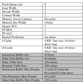
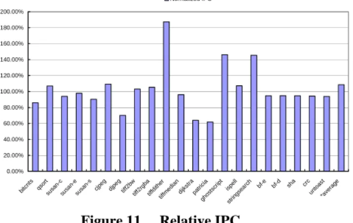
(5) relative memory traffic =. 4.1 Simulation Environment A modified version of SimpleScalar-ARM[10,11] is used to execute the compressed program and model the additional fetch latency of code compression architecture. The architectural parameters listed in Table 1 are modeled after Intel’s SA-1100 StrongARM embedded processor except cache sizes. The instruction cache size is intentionally reduced to emphasize the effect of code compression. Table 1. Simulator Configuration. traffic of compressed system + decompression overhead ————————————————————————— traffic of original system All traffics are measured with the number of word transfers on system bus since it’s common for such systems to have bus width of 32 bits. For example, a cache miss induces 4 word transfers to fill the 16-byte cache line while an inline data buffer miss induces 2 word transfers, one for compressed datum load and the other for slow dictionary lookup. I-Cache Miss. Instruction Buffer size Inline Data Buffer size Static Table Size Dynamic Table Size Instruction Buffer Miss Penalty Fast Dictionary Miss Penalty Inline Data Buffer Miss Penalty. Inline Data Buffer Miss. 100.00%. 80.00%. 60.00%. 40.00%. 20.00%. cr un c to as *a ve t ra ge. sh a. bf -d. 0.00% bf -e. D-Cache. Fast Dictionary Miss. 120.00%. 8 2 1 2 64 cycles 4 bytes 1 1 1 not taken 4 KB / line size=16 bytes / direct map 8 KB / line size=16 bytes / direct map 16 bytes 64 entries 256 entries 256 entries 1 cycle (I-Cache hit) 64 cycles(I-Cache miss) 64 cycles 128 cycles. bi tc nt s qs o su rt sa nsu c sa nsu e sa ns cj pe g dj pe g tif f2 bw tif f2 rg ba tif fd it tif her fm ed ia n di jk st ra pa t gh rici os a ts cr ip t is st rin pe g s ll ea rc h. Fetch Queue size Issue Width Decode Width Commit Width Memory Access Latency Memory Bus Width Integer ALU FP MUL FP ALU Branch Prediction I-Cache. Figure 9. Relative Memory Traffic. The colored columns in Table 1 are the parameters of the decompression unit. The miss penalties listed above do not include the delay due to bus contention failure. However the bus arbitration and contention behaviors are correctly modeled in the simulator, so the actual latencies collected in our result are possibly longer than listed. The sizes of dynamic and static table are selected based on result of preliminary experiment on fast dictionary structure. Our result shows that for a total of 512 table entries, the static/dynamic allocation of 256/256 has best adaptability throughout all benchmarks. To evaluate the relative performance of memory traffic and IPC, all benchmarks are executed on original SimplScalar-ARM with the same configuration listed in Table 1 to collect baseline statistics of original system.. 4.2 Simulation Result: Memory Traffic In this paper we intend memory traffic as the whole amount of memory transfers induced by instruction fetching. For the original system only instruction cache misses will incur memory transfer, but for the decompression-on-fetch architecture we devised, two additional overhead will be accumulated: fast dictionary miss and inline data buffer miss. The relative memory traffic is obtained from the following formula:. In Figure 9 we can see instruction cache miss times of all benchmarks are reduced. Most benchmarks (14 out of 18) still has more than 38% memory traffic reduction after accumulating the decompression overhead. The memory traffic summation of all benchmarks are calculated in both compressed and baseline system to derive averaged relative traffic. The average traffic ratio over all benchmarks is 52.38%, i.e. 47.62% memory traffic reduction on average.. 4.3 Simulation Result: IPC The IPC relative to original system is defined as: IPC of compression system relative IPC = ————————————— IPC of original system As we supposed, the decompression overhead will be redeemed by the virtual expansion of cache capacity. In Figure 10, most benchmarks (15 out of 18) achieve more than 80% relative IPC and 8 of them even outperform the original system. The average IPC of all programs is derived from the following formula: Total instruction count average IPC = ————————————— Total cycle count where total instruct count is the summation of committed instruction count from all executed benchmark, and total cycle count is the accumulated. - 240 -.
(6) cycle count of all executed benchmark. The average IPC reaches 108% of original system and indicates a speedup of 1.08 over original system.. Normalized IPC 200.00% 180.00% 160.00% 140.00% 120.00% 100.00% 80.00% 60.00%. performed cycle-accurate performance simulation on 18 embedded benchmarks selected from MiBench. The memory bandwidth is evaluated with traffic reduction and IPC gain. The proposed architecture achieves speedup of 1.08 over the baseline system and 47% reduction on memory traffic. For an embedded system, it’s common to have multiple bus masters connected to system bus and contend for bandwidth. Reduction on the memory traffic from processor can relieve the contention and potentially increase system performance. Moreover, the reduction on bus traffic also contributes to dynamic energy saving since the activities on bus lines are reduced.. 40.00%. References. 20.00%. cr un c to as *a ve t ra ge. sh a. bf -e. bf -d. bi tc nt s qs o su rt sa nsu c sa nsu e sa ns cj pe g dj pe g tif f2 bw tif f2 rg ba tif fd it tif her fm ed ia n di jk st ra pa t gh rici os a ts cr ip t is st ri n p e gs ll ea rc h. 0.00%. Figure 11. Relative IPC. 4.4 Hardware Cost Estimation The majority of the decompression unit is memory component like cache or buffer. So we tried to estimate the approximate hardware cost of the decompression unit in the form of required memory capacity. The first row of Table 2 lists our baseline for evaluation and its cost is estimated using the capacity summation of tag array and data array of the 4K instruction cache. Our code compression system is labeled 4K+cc in the table and the cost is estimated using capacity accumulation of instruction buffer, inline data buffer, fast dictionary and 4K cache. Additional performance reports of the 18 benchmarks are generated using an 8-KB instruction cache configuration and the average data are collected. The last row of Table 2 lists the cost and performance of the 8K-cache system. Table 2. Cost and Performance Comparison 4K 4K+cc 8K. Total Memory 37,888 bits 62,466 bits 75,264 bits. Area Cost 100% 164.87% 198.65%. Traffic Reduction 0% 47.62% 41.59%. Relative IPC 100% 108.52% 131.10%. From the table we can tell that our code compression architecture can achieve even better memory traffic reduction rate than a system with doubled cache capacity. The hardware cost of decompression unit is approximately 65% of a 4K direct-mapped instruction cache while a 8K-cache system needs 98% additional cost.. 5. 1.. S. Segars, K. Clarke, and L. Goude, “Embedded Control Problems, Thumb and the ARM7TDMI,” IEEE Micro, vol.16, no.6, pp.22-30, 1995. 2. K.D. Kissell, “MIPS16: High-Density MIPS for the Embedded Market,” Proc. Real Time System ’97 (RTS97), 1997. 3. IBM, “CodePack PowerPC Code Compression Utility User’s Manual Version 3.0,” IBM, 1998. 4. Yuan Xie, Wayne Wolf, Haris Lekatsas, “Profile-driven Selective Code Compression,” IEEE Design Automation and Test in Europe Conference and Exhibition, 2003. 5. Luca Benini, Francesco Menichelli, Mauro Olivieri, “A Class of Code Compression Schemes for Reducing Power Consumption in Embedded Microprocessor Systems,” IEEE Transactions on Computers ,Volume 53, NO.4 ,APRIL 2004. 6. J. Ziv and A. Lempel, “A Universal Algorithm for Sequential Data Compression,” IEEE Trans. Information Theory, vol.23, no.3, pp. 337-343, May 1997. 7. I. Kadayif and M.T. Kandemir, “Instruction compression and encoding for low-power systems,” IEEE 15th International ASIC/SOC Conference, 2002. 8. Matthew R. Guthaus, Jeffrey S. Ringenberg, Dan Ernst, Todd M. Austin, Trevor Mudge, Richard B. Brown, “MiBench: A free, commercially representative embedded benchmark suite,” IEEE 4th Annual Workshop on Workload Characterization, Austin, TX, December 2001. 9. A. Wolf and A. Chanin, “Executing Compressed Programs on an Embedded RISC Architecture,” Proceedings of the International Symposium on Microarchitecture, pp. 81-91, December 2001. 10. D. Burger and T. Austin, “The SimpleScalar Tool Set, Version 2.0,” Computer Architecture News 25(3), pp. 13-25, June 1997. 11. SimpleScalar LLC, http://www.simplescalar.com/v4test.html. Conclusion. This paper proposes a scheme of code compression architecture to improve memory bandwidth of embedded systems. The devised decompression unit can be easily integrated into existing embedded systems because no modification is done on processor and cache interfaces. We applied it to an ARM platform and. - 241 -.
(7)
數據
+3
相關文件
• The memory storage unit holds instructions and data for a running program.. • A bus is a group of wires that transfer data from one part to another (data,
Adding an external gigabit interface to every computing node for external connectivity to data storage systems and other computational resources is not practical, nor will it
Nonsmooth regularization induces sparsity in the solution, avoids oversmoothing signals, and is useful for variable selection.. The regularized problem can be solved effectively by
2 路組相聯的 Cache 結構 4K bytes 的 Cache 大小 4 Words 的 Cache line 大小 讀操作分配策略. 提供使 Cache line 無效的命令 提供預取 Cache line 的命令
For goods in transit, fill in the means of transport in this column and the code in the upper right corner of the box (refer to the “Customs Clearance Operations and
Looking for a recurring theme in the CareerCast.com Jobs Rated report’s best jobs of 2019.. One
Graduate Masters/mistresses will be eligible for consideration for promotion to Senior Graduate Master/Mistress provided they have obtained a Post-Graduate
Taking second-order cone optimization and complementarity problems for example, there have proposed many ef- fective solution methods, including the interior point methods [1, 2, 3,
