利用封包標誌追蹤攻擊者並降低封包遺失時之錯誤率
64
0
0
全文
(2) 利用封包標誌追蹤攻擊者並降低封包遺失時 之錯誤率. 研究生:林怡彣. 指導教授:李程輝 教授. 國立交通大學 電信工程學系碩士班. 中文摘要. 隨著網路應用服務的增加,網路安全的議題也就受到廣泛的重視,如何偵 測 攻 擊 並 找 到 攻 擊 者 就 成 為 近 年 來 研 究 的 重 點 。 決 定 式 封 包 標 誌 (DPM; Deterministic Packet Marking) 是其中一種封包標誌的方法,這種方法只需在 邊緣路由器(edge router)上執行標誌的動作,和其他封包標誌的方法相比,較 有擴充性且不會洩漏網路拓樸;此外決定式封包標誌更可以解決虛假標誌 (marking spoofing)的問題,攻擊者無法假造標誌影響被攻擊端的判斷。由於封 包標頭(header)只有十七個位元可以用來標誌,若要完整攜帶路由器三十二位 元的位址,需要兩個以上的封包,因此如何有效率的利用封包攜帶資訊,並降 低受害端重組位址的複雜度和錯誤率是問題所在。之前所提出之決定式封包標 誌的演算法誤判率太高,而且沒有考慮部分標誌封包遺失時,受害端重組出位 址的遺漏率。因此本論文提出一個新的演算法,可以大幅降低錯誤率,並提供 封包遺失補救的辦法,以提升錯誤率的方式降低遺漏率。. i.
(3) A New DPM Scheme with an Optional Lost-Correction Process for Tracing Multiple Internet Attackers. Student: Yi-Wen Lin. Advisor: Prof. Tsern-Huei Lee. Institute of Communication Engineering National Chiao-Tung University. Abstract. Deterministic packet marking (DPM) has recently been proposed as an alternative approach for tracing attackers. It is more scalable, simple to implement, backward compatible with Internet equipments that do not implement it, and requires no extra bandwidth. Besides, service providers can implement DPM without revealing their internal network topology. Unfortunately, the false positive rate of the previous DPM schemes could be very high. And the previous DPM schemes all discuss their performances under the assumption that victims receive all kinds of the marked packets. In realistic, the victims will collect the marked packets in a time interval and they can’t identify if all marked packets are received. In this paper, a new DPM scheme is proposed with an optional lost-correction process that can reduce the false negative rate caused by not receiving some marked packets. Compared with the DPM-Hash scheme, for 1K simultaneous attackers, the false positive rate of the proposed scheme without lost-correction process is around 0.11% and the reconstruction process is much faster.. ii.
(4) 誌謝. 首先,感謝我的指導教授-李程輝教授,在教授的指引下我很快進入狀況, 論文研究的過程中,教授給予充分的信任,讓我選擇有興趣的題目研究,並提 供中肯且實用的建議。研究所兩年的時間,在李教授的指導下,不論是研究方 法或是態度,都讓我獲益良多。. 感謝網路技術實驗室的學長們,在生活和研究上對我的關懷,尤其是 William 學長在繁忙的工作下,抽空指導我的研究,使我看到更多層次的問題。 也感謝實驗室的同學們:孟諭、易霖、冠亨、偉臣、景融、偉倫、偉志、文 彬、雅婷、謹慧和名駿,讓我在專心研究之餘,還可以有豐富的休閒生活。另 外,感謝實驗室的學弟妹和朋友們,陪我度過兩年快樂充實的研究所生涯。. 最後,我要特別感謝我的父母和親人,感謝你們永遠給予我無限的支持和 鼓勵,讓我有信心接受挑戰,突破一個個關卡,你們無止盡的信任和關心是我 最大的支柱。. 謹以此篇論文獻給所有人曾經關心我和支持我的親友。. Contents iii.
(5) 中文摘要. i. English Abstract. ii. 誌謝. iii. Contents. iv. List of Tables. vi. List of Figures. viii. Chapter 1. Introduction. 1. Chapter 2. Related Works. 4. 2.1 Introduction of DPM………………………………………………. 4. 2.2 The advantages of DPM………………………………………….... 5. 2.3 The basic DPM scheme……………………………………………. 6. 2.3.1. The coding of marks……………………………………….. 6. 2.3.2. The reconstruction process……………………………….... 7. 2.3.3. Problems………………………………………………….... 7. 2.4 The DPM-AD scheme……………………………………………... 8. 2.4.1. The coding of marks……………………………………….. 8. 2.4.2. The reconstruction process……………………………….... 9. 2.4.3. Performance analysis………………………………………. 10. 2.4.4. Problems………………………………………………….... 12. 2.5 The DPM-Hash scheme……………………………………………. 13. 2.5.1. The coding of marks……………………………………….. 13. 2.5.2. The reconstruction process……………………………….... 14. 2.5.3. Performance analysis………………………………………. 16. 2.5.4. Problems………………………………………………….... 19. iv.
(6) Chapter 3 3.1. The Proposed DPM Scheme. 21. The coding of marks…………………………………………….... 21. 3.2 The reconstruction process……………………………………….... 23. 3.3 The lost-correction process………………………………………... 27. Chapter 4. 35. Performance Analysis. 4.1 Reconstruction complexity and false positive rate………………... 4.1.1. 35. The analysis of reconstruction process…………………….. 35. The analysis of lost-correction process…………………….. 38. 4.2 False negative rate………………………………………………..... 43. 4.1.2. Chapter 5. Simulation Result. 45. 5.1 The false positive rate of the proposed scheme without lost-correction process…………………………………………….... 45. 5.2 The false negative rate………………………………………………. 46. 5.3 The false positive rate of the proposed scheme with lost-correction process……………………………………………………………… Chapter 6. 48 50. Conclusion. Bibliography. 51. Appendix. 53. v.
(7) List of Tables 2-1. Relationship between a , k , s , d , N MAX , and E [ D ] …………... 12. 2-2. Eight different kinds of marks of DPM-Hash scheme………………. 14. 2-3. Definitions, the average number of matches required, and the average size of the sets used in Stage 1 reconstruction…………….... 17. 2-4. Definitions, the average number of hashes, the average number of matches, and the average size of the sets used in Stage 2 reconstruction………………………………………………………... 18. 4-1. The average number of hashes, matches, xors required, and the average size and number of false positives of the sets………………. 37. 4-2. The complexity of the reconstruction_1……………………………... 40. 4-3. The complexity of reconstruction_2; I 2 = N ′ for N ≥ 24 …………. 40. N3 − N2 for N ≥ 25 ….. 217. 41. 4-4. The complexity of reconstruction_3; I 3 =. 4-5. The complexity of reconstruction_4; I 4 = R +. N ′5 − N ′4 ⎛ N′ ⎞ ⎜ 1 − 14 ⎟ 38 2 ⎝ 2 ⎠. and R = N − N ′ ……………………………………………………… 4-6. The complexity of reconstruction_5; I 5 = R +. N ′2 − N ′ ⎛ N′ ⎞ ⎜ 1 − 14 ⎟ 3 2 ⎝ 2 ⎠. and R = N − N ′ ……………………………………………………… 4-7. The complexity of reconstruction_6; I 6 = R +. 42. N ′4 − N ′3 ⎛ N′ ⎞ ⎜ 1 − 14 ⎟ 24 2 ⎝ 2 ⎠. and R = N − N ′ ………………………………………………………. vi. 41. 42.
(8) 4-8. The complexity of reconstruction_7. I7 = R +. N ′6 − N ′5 ⎛ N′ ⎞ ⎜ 1 − 14 ⎟ 52 2 ⎝ 2 ⎠. and R = N − N ′ ……………………………………………………… 4-9. The complexity of reconstruction_8. I8 = R +. 43. N ′7 − N ′6 ⎛ N′ ⎞ ⎜ 1 − 14 ⎟ 66 2 ⎝ 2 ⎠. and R = N − N ′ ……………………………………………………... 43. 5-1. The detail comparison of the DPM-AD, DPM-Hash, and the proposed scheme without lost-correction process…………………... 46. A1. Possible combinations of d , a , and s …………………………….. 54. A2. Minimum false positive rates for M = 4096 and N = 1024 ………. 54. vii.
(9) List of Figures 2-1. The architecture of the DPM algorithm…………..…………………. 5. 2-2. The schematics of the DPM-AD scheme………………………...….. 9. 2-3. An example of RecTbl, where k , d , and a are 16, 11, and 2, respectively…………………………………………………………. 10. 2-4. The false negative rate over different percentage of packet lost for. N =1024 of DPM-Hash Scheme……………...…………………..... 20. 3-1. Eight different kinds of marks of the proposed scheme………...….... 23. 3-2. The Pseudo code of reconstruction process of the proposed scheme.. 25. .3-3. The flow chart of reconstruction process of the proposed scheme….. 26. 3-4. The flow chart of the reconstruction process with packet-lost correction process…………………………………………..……...... 28. 3-5. The flow chart of one sub loop of lost-correction process: reconstruction_1………………………………………………….…. 29. 3-6. The flow chart of one sub loop of lost-correction process: reconstruction_2………………………………………………..……. 30. 3-7. The flow chart of one sub loop of lost-correction process: reconstruction_3…………………………………………………....... 31. 3-8. The flow chart of one sub loop of lost-correction process: reconstruction_4…………………………………………..………….. 31. 3-9. The flow chart of one sub loop of lost-correction process: reconstruction_5………………………………………..………....….. 32. 3-10. The flow chart of one sub loop of lost-correction process: reconstruction_6……………………………………..………............. viii. 33.
(10) 3-11. The flow chart of one sub loop of lost-correction process: reconstruction_7……………………………………………..…...…. 33. 3-12. The flow chart of one sub loop of lost-correction process: reconstruction_8…………………………………………..…………. 33. 5-1. The false positive rate over different N of the proposed scheme without lost-correction process……………………………..……....…. 46. 5-2. The false negative rate over different packet lost rate of DPM-Hash scheme, the proposed scheme with and without lost-correction process……………………………………………………………….... 47. 5-3. The comparison of the simulation results and the performance analyses of false negative rate…………………………………………. 48. 5-4. The false positive rate and false negative rate of the proposed scheme with or without lost-correction process……………...…………..……. ix. 49.
(11) Chapter 1 Introduction. Chapter 1 Introduction. As more and more services are provided on Internet, the secure of Internet becomes an important topic. Distributed denial-of-service (DDoS) is a well known attack that uses lots of compromised slaves to generate many packets to occupy the resources of network elements so that normal services are seriously degraded or totally denied [1]. Different to DDoS, there’s another kind of attack, the attackers only generate a few well-targeted packets and a system will be disabled. To deal with these attacks, a great amount of effort has been directed to the network security issues. There are two considerations of Internet security including determining if an attack occurs and identifying the sources of offending packets. Anomaly detection usually based on the records of ordinary traffics, if some statistics of flows change a lot suddenly that will be thought as abnormal. For example, the ratio of the number of packets a host sent to it receive will not change a lot [2]. Thus if a host continue sending packets without receiving, this host may be suspicious. After an attack is detected, finding out the sources of the offending packets is therefore an important task to make the attackers accountable. Unfortunately, because of the anonymous nature of the Internet Protocol, it is difficult to identify the true source of a packet if the source wishes to cancel it. Moreover, the network routing infrastructure is stateless and basically based on destination addresses. There is no entity in IP network that is responsible for ensuring the source address is correct. So the address contained in an attack packet can be easily spoofed and the IP traceback problem concerns tracing spoofed packets to identify the machines that directly generate the attack packets. Several solutions to this problem have been proposed. Firstly, since every packet contains its own source address, the simplest way for IP traceback is to reject IP spoofing. Ingress filtering, which is defined in RFC 2827 [3], and the fundamental idea of this technique is to block all packets carrying invalid 1.
(12) Chapter 1 Introduction. source IP addresses at network edges. An ingress filtering enabled router will suppress packets arriving from a given network with source addresses that do not properly belong to that network. However, the problem of ingress filtering is that it has nearly no effect when only partial edge networks implement this technique. All edge networks have to implement the scheme to make it work and this is unlikely to happen in the near future. Therefore, other techniques that allow incremental deployment are necessary for IP traceback. The other solutions can be divided into two groups. One group involved centralized management, and logging of packet information on the network equipments. This kind of Scheme can trace not only the DDoS attack but also the attacks that require only one or a few packets. However, storing plain traffic logs on the routers is prohibitive because of memory requirement. These solutions introduce a large overhead, and are complex and not scalable. Selective logging [4] can reduce memory requirement by tracking only those commonly abused protocol packets, but it is nearly impossible to profile suspicious packets for all potential victims without a large portion of packets passing through the network. Another way to save memory, hash-based IP traceback, it uses hashing techniques to record the passage of individual packets through each auditing router [5] [6] [7]. The passage of packets is recorded by storing its digest to a digest table. An attack packet is considered passing one router if its digest maps to an existing pattern stored in the digest table of that router. For example, the Source Path Isolation Engine (SPIE) proposed in [5] [6] employs the space-efficient Bloom filter [8] that maps some data of the packets through multiple hash functions into a single array of bits.. Due to the collision of. hashing function (two data might have the same digest) there will be some false positives. The false positive rate is controlled by allowing an individual digest table to store limited number of digest sets [9]. Besides, the memory of router is not enough to carry all the digest tables in a long time. So the digest tables must reset for presently incoming packets and a victim may be too late to ask for the record of digests. Thus not only the number of packets a digest table can record but also the timing to reset a digest table should be thought carefully. Compared with the technique of IP traceback mentioned above, the processing overhead is mostly at router, there is another kind of scheme that require less overhead at router but more overhead at victim. These schemes developed by sending 2.
(13) Chapter 1 Introduction. probabilistic samples of auditing routers’ identifications on a flow's path to the destination. So the victim can reconstruct the attack path if sufficient packets are collected from the flow. However, the sampling nature of these approaches limits their applications to the path identification of flood-based attacks. ICMP traceback [10] [11] is proposed that router pick a packet statistically (1 in every 20000 packets recommended) and generate an ICMP traceback directed to the same destination as the selected packet. The ICMP message consists of the next and previous hop information, a times-tamp, and as many bytes of the traced packet as possible. Besides, the time to live TTL field is set to 255 and then the victim can use it to identify the order of attack packets. Probabilistic packet marking (PPM) [12] [13] [14], on the other hand, uses IP header bits in randomly selected packets to carry the information in-band. The marking probability is suggested to be 0.04 and every marked packet carries the information of the router address. When victim receives enough such packets, it can reconstruct the addresses of all the PPM-enabled routers along the attack path. An alternative approach, called deterministic packet marking (DPM), has recently been proposed for tracing attackers [15] [16]. These schemes will be introduced in next section. The basic DPM [15] has very high false positive rate when multiple attackers using the same source address to attack a victim. Moreover, if every attack packet carries a different source address, this scheme will be useless. And a modified DPM scheme, which we called DPM with address digest (DPM-AD), was proposed in [16] and developed to solve the problems encountered in the basic DPM scheme. However, we found that the false positive rate of the DPM-AD scheme could be large if the number of edge routers is larger than the number of simultaneous attackers that spread uniformly over the Internet. Then Professor Lee, William, and I had published another DPM scheme in ICC 2005 [17] called DPM-HASH. Our analysis and simulation result show that the DPM-HASH scheme can trace 1K simultaneous attackers at a false positive rate less than 0.5% with acceptable reconstruction complexity. But the false negative rate of our proposed scheme will be miserable when the victim doesn’t receive all marked packets. So in this paper, I present another DPM scheme and this scheme not only reduces the false positive rate but also contains an optional lost-correction process to lower down the false negative rate. 3.
(14) Chapter 2 Related Work. Chapter 2 Related Work. 2.1 Introduction of DPM Deterministic Packet Marking (DPM) is essentially a packet marking algorithm, and it was first introduced in [15]. The basic idea of DPM is that the edge routers mark all the received packets with 16-bit ID field and the reserved 1-bit Flag in the IP header. And the mark contains the partial address information of the interface on an edge ingress router that is closet to the packet source. Because only the edge routers can mark packet, the marks on packets remain unchanged as long as the packets traverse the network. As shown in Figure 2-1, to ensure that egress router will not overwrite the mark placed by an ingress router, the interfaces only mark the incoming packets. When an attack is happening, the victim can collect all the injurious packets and reconstruct the information of interface addresses from those packets.. 4.
(15) Chapter 2 Related Work. Figure 2-1. The architecture of the DPM algorithm[15]. 2.2 The advantages of DPM The DPM scheme use 17 bits in IP header for marking, so it required no extra bandwidth. Moreover, DPM is more scalable than other probabilistic packet marking scheme because it only requires edge routers to perform packet marking. Since all packets are marked before entering into the network, it can trace a large number of attackers simultaneously with only a few packets from each attacker. Besides, DPM is backward compatible with internet equipments that do not implement it. Different to PPM, which treat routers as atomic units of traceback, DPM treat interfaces as atomic units of traceback. Making interfaces the units of traceback enables packets traveling in one direction to be treated differently from the packets traveling in another direction, and thus the suspects will be reduced. Besides, there is 5.
(16) Chapter 2 Related Work. a security problem of PPM called marking spoofing. It caused from the fact that an attacker can inject a packet, which is marked with error information. And these fake marks may influence the correctness of the reconstruction process. Through special coding such behavior can be prevented, but it is not 100% proof. As for DPM, all packets which travel through the network are marked by routers in the network. Even the attacker create spoof mark, the mark will be covered by the ingress router, and every packet arrived to the victim is ensured to be correctly marked. On the other hand, a service provider can implement DPM without revealing its internet topology, because DPM only traceback the ingress point, not the full-path. In a datagram packet network, each packet may take different path from the source to the destination. Since every packet route individually, only the interface of the ingress router closest to the attacker must be the same. As a result, the address of an ingress point is as good as the full-path traceback in term of identifying the attackers.. 2.3 The basic DPM scheme 2.3.1 The coding of marks The problem of traceback can be thought as that 32-bit IP address needs to be transmitted to the victim and 17 bits in IP header are available to pass this information. Obliviously, a single packet will not be enough, and it will take at least two packets to transmit the whole IP address. In the basic DPM scheme [15], an IP address is split into two segments such that bit 0~15 forms segment 0 and bit 16~31 forms segment 1. The ID field of a packet will be marked with either of these two segments with equal probability and the RF bit is use to distingue what segment the packet contains. For 6.
(17) Chapter 2 Related Work. example, the RF bit will be set to “0” if it is segment 0, and to “1” if it is segment 1. Moreover, the randomness is necessary because a sophisticated attacker might send exactly every other packet to the victim. And therefore it might create a situation that only one part of the address is available to the victim.. 2.3.2 The reconstruction process As for the reconstruction process, a reconstruction table indexed by source address is maintained at the victim. When an attack packet is received, the victim checks to see if the table entry for the source contained in the packet already exists, and creates it if it did not. Then, the victim writes the appropriate bits into the ingress IP address value. The ingress interface address becomes available to the victim after its both segments are received. Because the victim only waits for two kinds of segments from one router interface, seven packets on average are enough to generate the address with probability of greater than 99%.. 2.3.3 Problems As pointed out in reference [16], there are two situations that will cause the failure of the basic DPM scheme. First, consider the situation that two hosts with the same source address attack the victim from different network, and let the ingress addresses corresponding to these two attackers are A0 and A1 . The victim would receive four address segments, A0 [0] , A0 [1] , A1[0] , and A1[1] all correspond to the same source address. The false positive rate, which is defined as the ratio of the 7.
(18) Chapter 2 Related Work. number of false positives to the number of attackers in this paper, would be 100% because only two out of four possible combinations are valid. The false positive rate increases as the number of hosts attacking the victim with the same source address increases. Second, if the attackers change the source address every time they send attack packets, then the victim will not be able to reconstruct any valid ingress address.. 2.4 The DPM-AD scheme 2.4.1 The coding of marks To solve the problems encountered in the above two situations, a modified hash-based DPM scheme was proposed in [16], and for convenience, we call this scheme DPM-AD. In this modified scheme, the 17 bits are divided into three fields:. d -bit digest field, a -bit address bits field, and s -bit segment number field. An IP address, possibly with padding bits, is divided into k = 2 s segments and each segment contains a bits. And the digest field of the mark from same router interface will always remain the same so that the victim can reconstruct the interface addresses by associating address segments with the same digest. Figure 2-2 shows the schematics of the DPM-AD scheme. Each of the k marks has address bits set to a different segment of the ingress address, and the segment number field will be set to the appropriate value. When a packet is received by a router, a mark is randomly selected with probability and is used to replace the packet ID field and the RF bit. It is possible to assign different values to d , a , and s as long as the values satisfy. d + a + s = 17 and a × 2 s ≥ 32 .. 8.
(19) Chapter 2 Related Work. Figure 2-2. The schematics of the DPM-AD scheme [16]. 2.4.2 The reconstruction process The reconstruction procedure of this scheme is divided into two parts. Firstly, the victim set the appropriate bits in RecTbl to indicate which marks arrived to the destination. A reconstruction table RecTbl is a 217 bit structure and consists of 2d area. Each area has k segments, and each segment consists of 2a bits. Figure 2-3 shows an example of RecTbl, where k , d , and a are 16, 11, and 2, respectively. When the victim receives an attack packet, the digest is extracted from the mark and the area where the bit will be set is determined. The segment number field in the mark indicates the segment in the RecTbl area, and the value of address bits in the mark indicates the actual bits. Therefore, every certain bit in RecTbl indicates if the corresponding mark arrived to the victim. Secondly, to create permutations of segment, one segment has to be combined with other segments of the 9.
(20) Chapter 2 Related Work. same area. Then, the hash function is applied to each of these permutations. If the result matched to the area number, the permutation is considered a valid ingress address.. Figure 2-3. An example of RecTbl, where k , d , and a are 16, 11, and 2, respectively.[16]. 2.4.3 Performance analysis Obviously, even with an ideal hash function, false positive is inevitable if the number of simultaneous attackers N is greater than 2d . The authors evaluated the maximum number of attackers the DPM-AD scheme can tolerate under the constraint that the average number of false positives is less than 1% of N . The authors claim that the expected number of different values of a segment can be thought of as the expected number of the faces turning up on a 2 a -sided die after N 2d throws and. 10.
(21) Chapter 2 Related Work. the expected value is N. 1 ⎞ 2d ⎛ 2a − 2a ⎜1 − a ⎟ . ⎝ 2 ⎠ And then the expected number of permutations that result in a given digest for a given area of the RecTbl is k. N ⎡ ⎤ d 2 1 ⎛ ⎞ ⎢ 2a − 2a ⎜1 − ⎟ ⎥ a ⎢ ⎝ 2 ⎠ ⎥ ⎣ ⎦ . 2d. Therefore, the total number of permutations is obtained by multiplying the number of false positive for a single area by the number of areas, 2d . And the total number of false positives would be the total number of permutations less the number of valid ingress address. Under the condition that the number of false positives is less than 1% of N , the following inequality has to be solved for N : k. N ⎡ ⎤ d 2 1 ⎛ ⎞ ⎢ 2a − 2a 1 − ⎥ − N ≤ 0.01× N . ⎜ a ⎟ ⎢ ⎝ 2 ⎠ ⎥ ⎣ ⎦. And finally the maximum N , which would satisfy this inequality, N MAX , can be calculated. Moreover, the expected number of datagrams, E [ D ] , required to be marked by one interfaces in order for the victim to reconstruct its interfaces address is given by a Coupon Collector Problem: 1 ⎛1 ⎞ + ... + 1⎟ . E [ D] = k ⎜ + ⎝ k k −1 ⎠. Finally, Table 2-1 provides the relationship between a , k , s , d , N MAX , and. 11.
(22) Chapter 2 Related Work. E [ D ] . [16] Table 2-1. Relationship between a , k , s , d , N MAX , and E [ D ]. 2.4.4 Problems However, the calculation of the average number of false positives from the authors of DPM-AD scheme is too optimistic. In fact, the number of ingress router interfaces in the Internet, denoted as M , is much larger than the number of simultaneous attackers involved in an attack. With an ideal hash function that generates a d -bit digest, these M interfaces can be divided into 2d equal-size groups such that two interfaces are in the same group if and only if their digests are identical. The analysis presented in [16] assumed that on average N 2d interfaces are selected from each group, for example, with d = 11 and N = 2048 , one interface is selected from each group and thus there is no digest collision. A more realistic assumption is to select randomly N interfaces out of M . Under this assumption, digest collision and false positives will happen because it is possible to select multiple interfaces from the same group. And unfortunately, the number of false positives could be very large in this case. For example, consider the scenario with d = 11 ,. a = 2 , and s = 4 . If two interfaces are selected from the same group, then the number of possible combinations of address segments could be as large as 216 (every segment 12.
(23) Chapter 2 Related Work. has two address bits set to 1). Since the digest is only 11 bits, the average number of false positives is 216 211 − 2 = 30 . The evaluation presented in the Appendix shows that the average number of false positives is about 47.18% when M = 4096 and. N = 1024 with d = 11 , a = 2 , s = 4 . Therefore, when attackers spread uniformly over the Internet, the DPM-AD is not as scalable as was claimed in [16].. 2.5 The DPM-Hash scheme 2.5.1 The coding of marks To reduce the false positives of the previous DPM scheme, a new DPM scheme DPM-Hash scheme was proposed by Professor Lee, William, and I and published in ICC 2005 [17]. Similar to the basic DPM and the DPM-AD schemes, our proposed scheme utilizes 17 bits in packet header, and we allocate 3 bits to distinguish 8 different kinds of marks, which are summarized in Table 2-2. In Table 2-2, an interface address is split into three segments and represented by the same character with different subscripts such as a1a2 a3 , where, a1 , a2 , and a3 respectively denote the leading 14-bit, the next 14-bit, and the last 4-bit partial addresses. Moreover, each H i represents different hash functions or same hash function with different keys. As shown in Table 2-2, the first kind of mark contains the leading 14 bits of the IP address of the router interface that marks the packet and the second kind of mark contains the next 14 bits. If there are N attackers, the victim should receive N marks of the first kind and another N marks of the second kind, there will be N 2 possible combinations. Therefore, marks 3, 4, and 5 are designed to help the victim to find the right juxtaposition of every first kind of mark with a second kind of mark. 13.
(24) Chapter 2 Related Work. Each partial address digest contained in marks 3, 4, and 5 has seven bits. For example, every third kind of mark contains two digests, one for the leading 14 bits of the interface address (denoted as H 3 (a1 ) ) and the other for the next 14 bits (denoted as H 3 (a2 ) ). Moreover, for the victim to compute these digests, the hash function is assumed to be public and known to all Internet hosts. And then, the sixth kind of mark contains the last 4 bits of an IP address as well as a 10-bit digest of the complete 32-bit address. Finally, as the same reason as mark 3, 4, and 5, the seventh and the eighth kinds of marks contain the 14 bits digests of the complete 32-bit address generated by hash functions H 7 and H 8 , respectively. Table 2-2. Eight different kinds of marks of DPM-Hash scheme [17]. 2.5.2 The reconstruction process Assume that all the eight kinds of marks generated by every packet-marking enabled router interface are received at the victim. The reconstruction process is divided into two stages. In Stage 1, marks 1, 2, 3, 4, and 5 are used to determine the first 28 bits of interface addresses; in Stage 2, marks 6, 7, and 8 are used to reconstruct the complete IP addresses that mark the attack packets. 14.
(25) Chapter 2 Related Work. In Stage 1, firstly compute the digests of every received leading 14-bit and next 14-bit partial address. Then, for an arbitrary leading 14-bit partial address, say a1 , we should obtain the correct juxtaposition a1a2 with perhaps a few false ones after Stage 1. To obtain a1a2 , we need to find all the third kind of marks whose first digest is the same as H 3 (a1 ) , and let T3 denote the set of the second digests of those marks. Also, let S3 be the set of second 14-bit partial addresses such that x2 is in S3 if and only if (iff) H 3 ( x2 ) ∈ T3 . Of course, S3 contains a2 . With the help of the third kind of marks, we find the correct juxtaposition a1a2 with some false ones like a1b2 for every b2 ∈ S3 . Similar to T3 and S3 , let T4 be the set of second digests of those fourth kind of marks whose first digests are identical to H 4 (a1 ) , and S 4 , a subset of S3 such that x2 is in S 4 iff H 4 ( x2 ) ∈ T4 . Finally, let T5 be the set of second digests of those fifth kind of marks whose first digests are identical to H 5 (a1 ) and S5 be a subset of S 4 such that x2 is in S5 iff H 5 ( x2 ) ∈ T5 . Let U denote the set of all combinations found in Stage 1. In Stage 2, Pick a particular mark of the sixth kind, say P6 . Perform the hash function H 6 for every element of U combined with the last 4-bit partial address contained in P6 . Let S 6 denote the set of whole 32-bit address with digests identical to that contained in P6 . It is obviously that P6 contains at least one correct interface address and some false addresses. Define S 7 to be a subset of S6 such that y is in S7 iff H 7 ( y ) matches any seventh kind of marks. Finally, let S8 be a subset of S7 such that y is in S8 iff H 8 ( y ) matches any eighth kind of marks. After performing the procedure for every sixth kind of marks, we obtain N sets of addresses. Obviously, the union of these N sets of addresses contains N correct. 15.
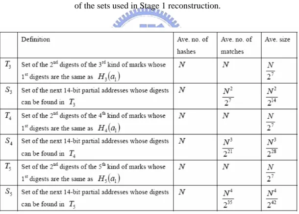
(26) Chapter 2 Related Work. interface addresses and some false ones.. 2.5.3 Performance analysis In this section, we estimate the performance of our proposed DPM-Hash scheme based on average analysis. We consider the case that N attackers send packets to the network through N different ingress router interfaces. Furthermore, we assume that no two router interfaces, which perform packet marking, have IP addresses with the same leading 14 bits or the same next 14 bits. The analysis includes reconstruction complexity, false positive rate, and the average number of packets required in reconstruction. As summarized in Table 2-3, let’s evaluate the complexity of Stage 1. Each of the hash functions H 3 , H 4 , and H 5 is performed for 2N times. Consider the procedure to obtain T3 , we need to match H 3 (a1 ) with the first digests contained in. N third kind of marks, and the average size of T3 is N 27 . To obtain S3 , all the hash values generated with H 3 for all the next 14-bit partial addresses are matched with the elements of T3 . The average number of matches performed is N 27 and the average size of S3 is ( N 27 ) 2 . To get T4 , N more matches for H 4 (a1 ) are performed and the average size of T4 is N 27 . To obtain S 4 , we need to perform ( N 27 ) 2 (size of S3 ) × N 27 (size of T4 ) = ( N 27 )3 matches and its average size is equal to ( N 27 ) 2 × N 27 ×1 27 (probability of matching an element of T4 ) = N 3 228 . T5 and S5 can be similarly obtained. To obtain T5 , the number of. 16.
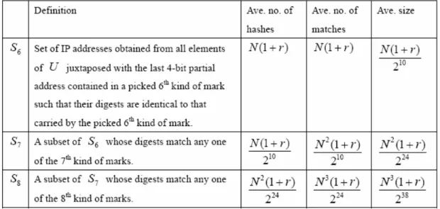
(27) Chapter 2 Related Work. matches required is N and its average size is N 27 . As for S5 , we need to perform N 4 235 matches and its average size is N 4 242 . Since there are N leading 14-bit partial addresses, the complexity of Stage 1 reconstruction includes. 6N hashes and N (3N + N 2 27 + N 3 221 + N 4 235 ) matches. Finally, at the end of Stage 1, we obtain the set U whose average size is equal to N (1 + r ) , where r = N 4 242 denotes the average size of S5 . For example, if N =1K, Stage 1 requires 6K hashes and. 223 (1 + 3 8 + 1 16 + 1 256) matches and the average number. of false juxtapositions per correct one is 1 4 . Table 2-3. Definitions, the average number of matches required, and the average size of the sets used in Stage 1 reconstruction.. And now let’s evaluate the complexity of Stage 2 (summarized in Table 2-4). For a selected sixth kind of mark, we need to perform N (1 + r ) hashes and the same amount of matches to get S 6 . The average size of S6 is N (1 + r ) 210 . To obtain. 17.
(28) Chapter 2 Related Work. S7 , the average number of hashes required is N (1 + r ) 210 [ N (1 + r ) 210 ] × N = N 2 (1 + r ) 210 .. and, matches,. The average size of S 7 is N 2 (1 + r ) 224 .. Finally, to obtain S8 , we need to perform N 2 (1 + r ) 224 hashes and N 3 (1 + r ) 224 matches. The average size of S8 , which also represents false positive rate, is given by N 3 (1 + r ) 238 . Notice that the actual size of S8 should be greater than or equal to 1 because it always contains a correct address. Again, for N =1K, Stage 2 requires N 2 (1 + r )(1 + N 210 + N 2 224 ). 220 (1.25)(2 + 1 16). =. hashes,. N 2 (1 + r )( N 210 + N 2 224 ) = 220 (1.25)(1 + 1 16) matches, and the expected false positive rate is about N 3 (1 + r ) 238 = 0.488%. We performed computer simulations 100 times for N =1K. In our simulations the interface addresses are randomly selected and the digests are created with MD5 algorithm. Results show that our proposed DPM scheme yields an average false positive rate of 0.5%, which matches well with the above approximate analysis. Table 2-4. Definitions, the average number of hashes, the average number of matches, and the average size of the sets used in Stage 2 reconstruction.. 18.
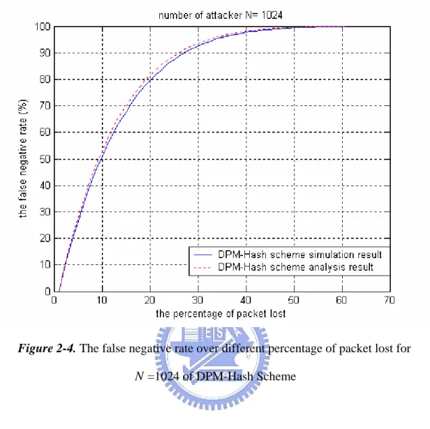
(29) Chapter 2 Related Work. As mentioned in [16], the average number of packets required in reconstruction can be modeled as a coupon collection problem. Since there are eight different kinds of marks, the number is equal to 22 for our proposed DPM scheme.. 2.5.4 Problems When DDoS attack occurs, the number of Internet packets may increase and some packets might lose. In performance analysis, we assume that the victim receive complete eight kinds of marks from each router interface. However, a more realistic situation is that victim will recognize attack packets and reconstruct the marked information in a determined time interval. It is not possible for the victim to determine whether all the eight marks of each router interface addresses are collected or not. Therefore, I consider the situation that victim doesn’t get some marked packets as marked packet lost. Without the information in these lost packets, the victim can’t determine all the router interface addresses and the addresses that the victim doesn’t find are regarded as false negatives. Furthermore, the false negative rate is defined as the ratio of the number of false negatives to the number of attackers. Let the packet lost rate be m , and the number of packet lost will be m(8 N ) . The probability that all the eight kinds of marks from one router are not lost is (1 − m)8 . Thus, the probability that victim can reconstruct that interface address is (1 − m)8 . On the other hand, the false negative rate is 1 − (1 − m)8 . As illustrated in Figure 2-4, for N =1K, the analysis and simulation result of false negative rate over different percentage of packet lost are matched. The result that the false negative rate will reach to 50% when 10% packet lost is miserable. 19.
(30) Chapter 2 Related Work. Figure 2-4. The false negative rate over different percentage of packet lost for. N =1024 of DPM-Hash Scheme. 20.
(31) Chapter 3 The Proposed DPM Scheme. Chapter 3 The Proposed DPM Scheme. 3.1 The coding of marks As mentioned before, there are 17 bits in the IP header can be utilized to be marked by the ingress routers. Same to the DPM-Hash scheme, we use 3 bits for index that distinguishes 8 different kinds of marks and 14 bits for the information of interface addresses. Moreover, in order to solve the false negative problem (when some marked packets lost) of the previous DPM scheme, we arrange that every bit of the IP address of the router interface must be send more than twice. And then the victim can reconstruct the router interface address with any three of the first four kinds of packets. As shown in Figure 3-1, a router interface address is divided into five segments such as a1a2 a3a4 a5 , where a1 , a2 , a3 , a4 individually denote different partial 7 bits of address and a5 represent the last 4 bits of address. And the eight kinds of marks can divide into two parts, the first four kinds of marks contain the information about the interface address called address marks, the others consist of the digests of partial interface addresses noted as digest marks. All of the address marks are composed of original address bit and the xor of two partial addresses. The first kind of mark contains a1 , which is the leading 7 bits 21.
(32) Chapter 3 The Proposed DPM Scheme. of the IP address, as well as the xor of the second 7-bits address a2 and a5 . Because a2 denotes 7 bits and a5 only contains 4 bits, we assign that xor (a2 , a5 ) is actually the last 4 bits of a2 xor a5 , and thus the leading 3 bits of xor (a2 , a5 ) and. a2 are the same. Similar to mark 1, the beginning 7 bits of mark 2, 3, and 4 are respectively a2 , a3 , and a4 , and the following 7 bits are the xor results of two partial IP addresses as shown in Figure 3-1. In order to satisfy the condition that each bits of the IP address must be send at least twice, the coding of the marks should be carefully designed. For example, both mark 1 and mark 4 contain the information of. a1 . Thus when the first mark lost on the way from the ingress router to the victim, the victim can still determine a1 from the forth mark by xor a5 and the last 7 bits of it (which is xor (a1 , a5 ) ). As for digest marks, they are designed to help the victim to find the correct IP addresses of router interfaces that mark the attack packets. If there are N attackers, the victim might receive N packets of each kind of marks. The victim needs to combine each kinds of marks, but only N of the combinations are correct. Therefore, through the comparing of the digests of those combinations with digest marks, the number of false candidates can be reduced. And to simplify the reconstruction process, the combinations must be scale down just after one address mark associate with another. Two adjacent address marks only contain 25 bits information of the address, thus every digest mark was calculated from 25-bits interface address. For example, the digest contained in mark 5, Hash(a1 , a2 , a3 , a5 ) , which is computed from the router interface address without a4 .. 22.
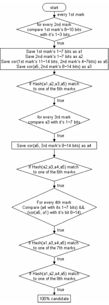
(33) Chapter 3 The Proposed DPM Scheme. Figure 3-1. Eight different kinds of marks of the proposed scheme. 3.2 The reconstruction process The pseudo code and flow chart of reconstruction process is shown in Figure 3-2 and Figure 3-3. Firstly, to find out the first 21 bits, which can be denoted by a1a2 a3 for convenience, the victim would combine N first kind of marks with N second kind of marks. For each first kind of mark, its 8th to 10th bits will be compared to all second kind’s 1st to 3rd bits, and any two packets match produce a combination. After associating first two kinds of marks, the last 4 bits of the address, which can be denoted as a5 , are determined by xor the 11th to 14th bits of mark 1 and 4th to 7th bits of mark 2. And then a3 can be ascertained by xor a5 and the 8th to 14th bits of the second kind of mark. By now, what the victim obtains is a lot of partial address combinations (the first 21 bits and the last 4 bits) with perhaps some false ones. Let the set of these partial address combinations be S1 . For each partial address in S1 , if its digest ( Hash(a1 , a2 , a3 , a5 ) ) matches to any of the N fifth kind of marks, the. 23.
(34) Chapter 3 The Proposed DPM Scheme. combination is considered more credible than before. The set of the combinations that have been confirmed by mark 5 is denoted as S 2 . Secondly, by connecting the partial 25-bits address in set S 2 and N third kind of marks, the victim will get the whole 32-bits interface address. As shown in Figure 3-2, the reconstruction process is similar to the association of the first two kinds of marks. For each combination in S 2 , its 15th to 21st bits (denoted as a3 ) will be compared with the leading 7 bits of all third marks, and any two match produce a combination. After that, the victim can get a4 from xor a5 and the other 7 bits of the selective third kind of mark, and therefore the whole address is determined. Let the set of these whole 32-bit address combinations be S3 . Then using N sixth kind of marks to check the accuracy of those whole addresses in S3 . For each address in S3 , if its digest of partial address bits, denoted as Hash(a2 , a3 , a4 , a5 ) , can be found in any mark 6, it is a member of S 4 . Finally, there are three more kinds of marks can be used to reduce the 32-bits address combinations in S 4 . Because all the 32 bits of addresses are determined, without considering that marked packets might lost, the fourth kind of marks can be regarded as digest mark. The addresses in S 4 whose a4 and xor (a1 , a5 ) match to any one of N fourth marks are denoted as S5 . After that, let S 6 be the set of the combinations in S5 which are confirmed by mark 7, and S 7 be the set of the combinations in S6 which are confirmed by mark 8. And at last, the candidates in S7 are the correct IP addresses of router interfaces that mark the attack packets.. 24.
(35) Chapter 3 The Proposed DPM Scheme. Figure 3-2. The Pseudo code of reconstruction process of the proposed scheme. 25.
(36) Chapter 3 The Proposed DPM Scheme. Figure 3-3. The flow chart of reconstruction process of the proposed scheme 26.
(37) Chapter 3 The Proposed DPM Scheme. 3.3 The lost-correction process As mentioned in the previous DPM scheme, for N =1K, if 10% of the marked packets lost on their way to the victim, the average false negative rate will reach to 54.78%. To solve this problem, we carefully design the eight kinds of marks, and consider an optional lost-correction process as shown in Figure 3-4. The basic idea of lost-correction process is to find out those combinations that produced by only seven kinds of marks. Thus if the victim only receive seven marks from one router, it still can reconstruct this interface address by lost-correction process. Of course, these new combinations contain false positives too. There is a tradeoff between false negative, false positive, and the complexity caused by the lost-correction process. The gray parts in Figure 3-4 represent the original reconstruction process, and the candidates resulted from this flow are considered 100% reliable. On the other hand, the victim can find out other combinations from the lost-correction process, but those candidates are less reliable. Moreover the lost-correction process basically composed by eight sub loops, reconstruction_1~ reconstruction_8, and the flow chart of these sub loops are shown in Figure 3-5~ Figure 3-12.. 27.
(38) Chapter 3 The Proposed DPM Scheme. Figure 3-4. The flow chart of the reconstruction process with packet-lost correction process. 28.
(39) Chapter 3 The Proposed DPM Scheme. Figure 3-5. The flow chart of one sub loop of lost-correction process: reconstruction_1. 29.
(40) Chapter 3 The Proposed DPM Scheme. Figure 3-6. The flow chart of one sub loop of lost-correction process: reconstruction_2. 30.
(41) Chapter 3 The Proposed DPM Scheme. Figure 3-7. The flow chart of one sub loop of lost-correction process: reconstruction_3. Figure 3-8. The flow chart of one sub loop of lost-correction process: reconstruction_4 31.
(42) Chapter 3 The Proposed DPM Scheme. Figure 3-9. The flow chart of one sub loop of lost-correction process: reconstruction_5. 32.
(43) Chapter 3 The Proposed DPM Scheme. Figure 3-10. The flow chart of one sub loop of lost-correction process: reconstruction_6. Figure 3-11. The flow chart of one sub loop of lost-correction process: reconstruction_7. Figure 3-12. The flow chart of one sub loop of lost-correction process: reconstruction_8 33.
(44) Chapter 3 The Proposed DPM Scheme. Every comparison of the original reconstruction process, which is presented by diamond, has two outcomes true or false. If the outcome is false that means one kind of mark or the combination produced before doesn’t match to any of another kind of marks. There are two reasons for not matching, one is that the combination is a wrong one, and it doesn’t pass the check. The other reason is the victim hasn’t got the correspondent mark because this mark lost on the way to the victim or the router hasn’t sent this kind of mark. And when one combination enter the lost-correction process, the sub loop reconstruction_ i will compute some combinations without the i th kind of marks. That means these candidates are reconstructed by only seven kinds. of marks and considered less credible. Take reconstruction_2 for example, if one first kind of mark doesn’t match to any second mark that means some second marks might lose and this first mark will go to the state named reconstruction_2. The other fan-in of reconstruction_2 is from the second comparison of the flow chart. After the first comparison, one first mark might match to several second marks and create some combinations. But if all these combinations don’t pass the digest check of mark 5, the corresponding mark 5 might lost or all the associated second marks are not correct. So the other fan-in of reconstruction_2 is necessary. The detail flow chart of reconstruction_2 is shown in Figure 3-6, and it is similar to the original reconstruction process. Without the corresponding second mark, the first mark firstly connects with fourth marks and then. a1 a2 a4 a5 is determined. After that the eighth marks are used to check the accuracy of the combinations found before. Then the victim can associate the combinations and the last address mark, mark 3, to produce the whole address bits. The other digest marks are used to determine the correct candidates. Besides, the flag n2 denotes the number of candidates created from reconstruction_2. 34.
(45) Chapter 4 Performance Analysis. Chapter 4 Performance Analysis. 4.1 Reconstruction complexity and false positive rate In this Chapter, we estimate the performance of the proposed DPM scheme base on average analysis. We consider the case that N attackers send packets to the network through N different ingress routers. And the ingress routers mark every incoming packet by the eight different marks with equal probability and every kind of packets has the same lost rate. The analysis includes reconstruction complexity, false positive rate, false negative rate, and the average number of packets required in reconstruction.. 4.1.1 The analysis of reconstruction process Table 4-1 summarizes the definitions of each set, the average numbers of hashes, matches, and xors required, and the average size and false positives of each set. Considering the procedure of finding out the set of 25-bit address combinations, which is denoted as S1 , we need to match N first marks to N second marks and it required N 2 matches. The average size of S1 is N + ( N 2 − N ) 23 with N correct address and ( N 2 − N ) 23 false positives. After connecting the first two kinds. 35.
(46) Chapter 4 Performance Analysis. of marks, we need to perform. ( N + ( N 2 − N ) 23 ) × 2 xors to get the original. partial addresses. To determine the members in S 2 , each combination in S1 will be hashed and its digest is used to match to N. mark 5. And this required. N + ( N 2 − N ) 23 hashes and ( N + ( N 2 − N ) 23 ) × N = N 2 + ( N 3 − N 2 ) 23 matches. After that, to obtain S3 from N + ( N 3 − N 2 ) 217 combinations of S 2 , we need to perform ( N + ( N 3 − N 2 ) 217 ) × N = N 2 + ( N 4 − N 3 ) 217 matches to combine the partial addresses in S 2 with the third marks. Besides, the average size of S3 is N + ( N 4 − N 3 ) 224 . Thus the number of xors required to find out the original 22nd to 29th bits of addresses is as same as the number of combinations in S3 . To get S 4 , N + ( N 4 − N 3 ) 2 24. more. hashes. and. ( N + ( N 4 − N 3 ) 224 ) × N. =. N 2 + ( N 5 − N 4 ) 224 more matches is required, and the average size of S 4 is N + ( N 5 − N 4 ) 238 . And then, each address in S 4 performs xor of its leading 7 bits and its last 4 bits in order to match to the last 7 bits of the forth marks. Therefore, to. obtain. S5 ,. the. calculation. ( N + ( N 5 − N 4 ) 238 ) × N =. required. N 2 + ( N 6 − N 5 ) 238. N + ( N 5 − N 4 ) 238. xors. and. matches. Then, to get. S6 ,. N + ( N 6 − N 5 ) 252 (which is equal to the average size of S5 ) more hashes and ( N + ( N 6 − N 5 ) 252 ) × N = N 2 + ( N 7 − N 6 ) 252 more matches are performed, and the average size of S6 is N + ( N 7 − N 6 ) 266 . At last, to find S 7 , it required N + ( N 7 − N 6 ) 2 66. hashes and. ( N + ( N 7 − N 6 ) 266 ) × N = N 2 + ( N 8 − N 7 ) 266. matches. The average number of false positives of the proposed scheme is ( N 8 − N 7 ) 280 . Compared with the DPM-Hash scheme, for N =1K, the false positive rate of the. 36.
(47) Chapter 4 Performance Analysis. proposed scheme is 0.096893%, and the DPM-Hash scheme is 0.488%. The false positive rate of the proposed scheme is four times less than the DPM-Hash scheme. Moreover, comparing the complexity of two schemes, the DPM-Hash scheme required 220 (2.578125) hashes and 220 (1.578125) matches, but the proposed scheme. require. 220 (0.265369). 220 (0.191482). xors. .. N 2 (1 + N 4 242 )(1 + N 210 + N 2 224 ). 220 (211.066147). hashes, (The. DPM-Hash. hashes and. matches,. scheme. and. required. N 2 (1 + N 4 242 )( N 210 + N 2 224 ). matches.) The hash function is the most time-consuming part of the reconstruction process and much more complexity than match or xor. function. So the. reconstruction process of the proposed scheme is much faster than DPM-Hash scheme. Table 4-1. The average number of hashes, matches, xors required, and the average size and number of false positives of the sets. 37.
(48) Chapter 4 Performance Analysis. 4.1.2 The analysis of lost-correction process The average number of hashes, matches, xors required, and the average size and number of false positives of the sub loops reconstruction_1~reconstruction_8 are illustrated in Table 4-2~Table 4-9. We assume that each kind of marks has the same lost rate, and the numbers of each kind of marks the victim received, denoted as N ′ , are equivalent. Take reconstruction_1 for example, the complexity is shown in Table 4-2. For every second mark, we assume that its corresponding first mark lost, so every second mark should be sent into reconstruction_1. Thus the average size of input of reconstruction_1 is N ′ . As the flow chart shown in Figure 3-5, there are six comparisons in reconstruction_1 and the operations needed in every comparison are illustrated in 1st row to 6th row accordingly. Moreover, the candidates found from reconstruction_1 may contain N ′ combinations, which are already found in the original reconstruction process, and around N − N ′ new combinations. As shown in Figure 3-4, the sub-loop reconstruction_2 has two fan-ins from two different comparisons. But when N ≥ 2 4 , the first comparison will always be true. Because on average at least two second marks will match to one first mark (only 3 bits are used for matching). Even if one of the second marks lost, its corresponding first mark will still match to the other one and the outcome of comparison will be true. As the same reason when ( N 3 − N 2 ) 217 ≥ 28 ≈ N ≥ 25 , reaonstruciton_3 nearly has only one kind of input too. In this analysis, we consider that the victim is under DDoS attack and the number of attackers is much more than 25 . On the other hand, if on average each first mark at least associate with two second mark, only one of the combinations is correct and the others can not pass the digest check of fifth mark. 38.
(49) Chapter 4 Performance Analysis. Therefore, every first mark will sent into reconstruction_2, and the average number of inputs of reconstruction_2 is N ′ . Moreover, the average number of inputs of reconstruction_3 is. ( N ′3 − N ′2 ) 217 . Similar to reconstruction_1, both the. combinations found from reconstruction_2 and reconstruction_3 include those already found in original reconstruction process and some new ones. Finally, the other sub-loops, reconstruction_4~ reconstruction_8 all have only one fan-in. As mentioned before mark 4~ 8 are considered as digest marks and without packet lost the correct combinations definitely can pass these checks. Therefore, the inputs of reconstruction_4 are those wrong combinations that do not pass the check of fourth marks and the combinations that their corresponding fourth marks lost. Each candidate found form these sub-loops is not identical to the candidate found from the original reconstruction process. Again, for N ′ = N =1K (which means no packet lost), the proposed scheme with lost-correction process required 220 (0.191482) + 220 (1.443705) = 220 (1.635187) hashes,. 220 (211.066147) + 220 (1710.272003) = 220 (1921.33815). 220 (0.265369) + 220 (1.700493) = 220 (1.965862). matches, and. xors . Compared with DPM-Hash. scheme, which required 220 (2.578125) hashes and 220 (1.578125) matches, the proposed scheme still has the advantage of faster reconstruction. However, for. N ′ = N =1K, each sub-loops will produce around 15 false positives, and the false positives rate will reach to 12.80%. The number of false positives will decrease when the packet lost rate increase. This will be shown in next Capture.. 39.
(50) Chapter 4 Performance Analysis. Table 4-2. The complexity of the reconstruction_1. Table 4-3. The complexity of reconstruction_2; I 2 = N ′ for N ≥ 2 4. 40.
(51) Chapter 4 Performance Analysis. Table 4-4. The complexity of reconstruction_3; I 3 =. N3 − N2 for N ≥ 25 217. N ′5 − N ′4 ⎛ N ′ ⎞ Table 4-5. The complexity of reconstruction_4; I 4 = R + ⎜1 − 14 ⎟ and 238 ⎝ 2 ⎠. R = N − N′. 41.
(52) Chapter 4 Performance Analysis. N ′2 − N ′ ⎛ N ′ ⎞ Table 4-6. The complexity of reconstruction_5; I 5 = R + ⎜1 − 14 ⎟ and 23 ⎝ 2 ⎠. R = N − N′. Table 4-7. The complexity of reconstruction_6; I 6 = R +. R = N − N′. 42. N ′4 − N ′3 ⎛ N ′ ⎞ ⎜1 − 14 ⎟ and 224 ⎝ 2 ⎠.
(53) Chapter 4 Performance Analysis. Table 4-8. The complexity of reconstruction_7. N ′6 − N ′5 ⎛ N ′ ⎞ I7 = R + ⎜1 − 14 ⎟ and 252 ⎝ 2 ⎠. R = N − N′. Table 4-9. The complexity of reconstruction_8. I8 = R +. N ′7 − N ′6 ⎛ N ′ ⎞ ⎜1 − 14 ⎟ and 266 ⎝ 2 ⎠. R = N − N′. 4.2 False negative rate As for the false negative rate, the proposed scheme without lost correction process and the DPM-Hash scheme basically use eight different kinds of marks, and the victim can’t reconstruct the router interface address if any eight marks lost. Which means the probability of finding one router interface address is equal to the probability that the victim get the whole eight marked packets. Let m be the packet lost rate, and the number of packet lost will be m(8 N ) . The probability that all eight kinds of marks from one router are not lost is (1 − m)8 . Therefore, the probability that the victim can fin out one router interface address by its receiving attack packets is (1 − m)8 . On the other hand, the false negative rate is 1 − (1 − m)8 . 43.
(54) Chapter 4 Performance Analysis. With lost-correction process, the victim can determine the interface address by any seven of the eight kinds of marks. As mentioned in last Chapter, this process will produce some new candidates, which are not 100% reliable. And these not 100% candidates contain the correct router addresses and some false ones. The probability that one of the eight kinds of marks lost is 8m(1 − m)7 . With lost-correction process, the victim still can determine one address even if one mark lost, therefore, the false negative rate will reduced to 1 − (1 − m)8 − 8m(1 − m)7 . The number of false positives produced from the lost-correction process will be shown in simulation result. As mentioned in [16], the average number of packets required in reconstruction can be modeled as a coupon collection problem. Since the proposed scheme and DPM-Hash scheme both use eight different kinds of marks, the average number of packets required in reconstruction is equal to 22.. 44.
(55) Chapter 5 Simulation Result. Chapter 5 Simulation Result. 5.1 The false positive rate of the proposed scheme without lost-correction process In our simulation the interface addresses are randomly selected and the digests are created with MD5 algorithm. Firstly, to compared with the DPM-Hash scheme, we performed computer simulations 100 times for N =1K. Results show that the average false positive rate of the proposed scheme without lost-correction is around 0.11%, which match well with the above approximate analysis. And the false positive rate over different N is shown in Figure 5-1. Moreover, the detail comparison of the DPM-AD, DPM-Hash, and the proposed scheme under different N is shown in Table 5-1. Under the consideration of lower false positive rate, the proposed scheme without lost-correction process is definitely the best choice.. 45.
(56) Chapter 5 Simulation Result. Figure 5-1. The false positive rate over different N of the proposed scheme without lost-correction process Table 5-1. The detail comparison of the DPM-AD, DPM-Hash, and the proposed scheme without lost-correction process. 5.2 The false negative rate On the other hand, the simulation result of the false negative rate over different packet lost rate for. N =1K is shown in Figure 5-2. As mentioned in performance 46.
(57) Chapter 5 Simulation Result. analysis, without lost correction process, the proposed scheme and the DPM-Hash scheme have the same false negative rate. As illustrated in Figure 5-2, the proposed scheme without lost correction process and the DPM-Hash scheme have almost the same curve, but the result is miserable. When 10% of packets lost, over 50% attacker can’t be found. To solve this problem, we introduce the lost-correction process, and under the same condition ( N =1K with 10% packets lost rate) the false negative rate is only 15%. By using the lost-correction process, the false negative rate can at moat be reduced by 35%.. Besides, to compare the simulation results with the. performance analyses of false negative, both of them are illustrated in Figure 5-3. The simulation results are matched to the performance analyses.. Figure 5-2. The false negative rate over different packet lost rate of DPM-Hash scheme, the proposed scheme with and without lost-correction process. 47.
(58) Chapter 5 Simulation Result. Figure 5-3. The comparison of the simulation results and the performance analysis of false negative rate.. 5.3 The false positive rate of the proposed scheme with lost-correction process Next, the false positive along with the lost-correction process is illustrated in Figure 5-4. As mentioned before, the lost-correction process produces candidates by only seven marks, so it will reduce the false negative rate but increase the false positive rate. The false positive rate is 12.80% if the victim receives all the mark packets; and 6.33% if the victim only receives 90% mark packets. Compared with the scheme without lost-correction process, which the false positive rate is only around 0.116%, the false positive rate is much higher. There is a trade off between false 48.
(59) Chapter 5 Simulation Result. negative rate and false positive rate, the victim can decide to use lost-correction process or not.. Figure 5-4. The false positive rate and false negative rate of the proposed scheme with or without lost-correction process.. 49.
(60) Chapter 6 Conclusion. Chapter 6 Conclusion. This study proposed a method based on deterministic packet marking (DPM) for a victim to find out the edge routers that the attack packets passed through. Compared with probabilistic packet marking, DPM has the advantages of scalable, simple to implement, no revealing of internal network topology, and guarantee of no spoofed marks. However, the previously proposed DPM schemes don’t consider the situation that victim may not receive all the marked packets and thus some router interface addresses might not be found. In this paper, we proposed a new DPM scheme which is more scalable than previous DPM schemes and has a lower false positive rate. Analysis results, which were verified with computer simulations, show that the proposed scheme can trace 1K simultaneous attackers at a false positive rate around 0.116% with faster reconstruction. Besides, we design an optional lost-correction process which can reconstruct one router interface address by any seven of the eight kinds of marks. The lost-correction process required acceptable complexity but has a tradeoff between the false negative rate and the false positive rate.. 50.
(61) Bibliography. Bibliography. [1]. Rocky. K. C. Chang.,. “Defending. against. flooding-based. distributed. denial-of-service attacks: a tutorial,” IEEE Communications Magazine, October 2002. [2] T. Gil and M. Poletto., “MULTOPS:a data structure for bandwidth attack detection,” In Proceedings of the 10th USENIX Security Symposium, August 2001, Washington D.C., USA. [3] P. Ferguson and D. Senie, “Network Ingress Filtering: Defeating Denial of Service Attacks which Employ IP Source Address Spoofing,” RFC 2827, IETF, May 2000. [4] G. Sager, “Security fun with OCxmon and cflowd,” Internet 2 Working Group Meeting, Nov. 1998, http://www.caida.org/projects/ngi/content/security/1198/. [5] A. C. Snoeren et al., “Single-Packet IP Traceback,” IEEE/ACM Trans. Net., vol. 10, no. 6, Dec. 2002, pp. 721-734. [6] A. C. Snoeren et al., “Hash-Based IP Traceback,” SIGCOMM'01, Aug. 2001. [7] T. H. Lee, W. K. Wu, and T. Y. William Huang, “Scalable Packet Digesting Schemes for IP Traceback,” IEEE International Conference on Communications 2004. [8] B. H. Bloom, “Space/Time Trade-Offs in Hash Coding with Allowable Errors,” Communication of ACM, July 1970, vol. 13, no. 7, pp. 422-426. 51.
(62) Bibliography. [9] L. Fan and P. Cao, “Universal Classes of Hash Functions,” Journal of Computer and System Sciences, 1979, pp. 143-154. [10] S. M. Bellovin, “ICMP Traceback Messages,” IETF draft, http://www.research.att.com/smb/papers/draft-bellovin-itrace-00.txt, 2000. [11] A. Mankin et al., “On Design and Evaluation of "Intention-Driven" ICMP Traceback,” Proc. IEEE International Conference on Computer Communications and Networks, Oct. 2001. [12] H. Burch and B. Cheswick, “Tracing Anonymous Packets to Their Approximate Source,” Proc. 2000 Systems Administration Conference, Dec. 2000. [13] S. Savage et al., “Network Support for IP Traceback,” IEEE/ACM Trans. Net., vol. 9, no. 3, June 2001, pp. 226-37. [14] D. X. Song and A. Perrig, “Advanced and Authenticated Marking Schemes for IP Traceback Messages,” Proc. IEEE Infocom '01, Apr. 2001. [15] A. Belenky and N. Ansari, “IP Traceback with Deterministic Packet Marking,” IEEE Communications Letters, Vol.7, NO. 4, April 2003 [16] A. Belenky and N. Ansari, “Tracing Multiple Attackers with Deterministic Packet Marking,” IEEE PACRIM’03, August 2003. [17] T. H. Lee, T. Y. William Huang, and Iven Lin, “A Deterministic Packet Marking Scheme for Tracing Multiple Internet Attackers,” IEEE ICC 2005.. 52.
(63) Appendix. Appendix Calculation of false positive rate for the DPM-AD scheme. In this appendix we present the false positive rate analysis for the DPM-AD scheme assuming M =4096, N =1024, d = 11 , a = 2 , and s = 4 . The Analysis can be easily generalized to different scenarios. Under the assumption, there are 211 areas, 16 segments in each area, and 2 2 possible partial addresses in a segment for the reconstruction process described in [12]. Moreover, since d = 11 , the M interfaces are divided into 211 groups. In other words, on average there are m = M / 211 interfaces in a group with the assumption that M is a multiple of 2d . We want to select N interfaces out of M . Let ni denote the number of groups with i interfaces selected. m. Let n = [n0 , n1 , n2 ,..., nm ] be an ordered set of ni , 0 ≤ i ≤ m , such that ∑ i ⋅ ni = N . i =0. m. m. i =0. i =0. Also, let Pn = {2d !/[(∏ ni !)CNM ]}∏ (Cim ) ni. denote the probability of n , where. Cba = a !/[b !( a − b)!] . The expected number of address combinations in an area with i s. interfaces selected, denoted by Gi , is given by Gi = [2 a − 2 a (1 − 1/ 2a )i ]2 .. 53.
(64) Appendix. For a given n , the expected number of false address combinations An is given by m. An = (∑ ni Gi − N ) / 2d .. Finally, the average number of false positives is equal to. i =0. ∑ Pn ⋅ An and the false positive rate can be evaluated by (∑ Pn ⋅ An ) / N . n. n. For the considered scenario, the false positive rate is equal to 47.18%. Table A2 shows the false positive rates for various values of N . Note that there are multiple choices for d , a , and s as long as they satisfy d + a + s = 17 and a × 2 s ≥ 32 (see Table A1). The false positive rates shown in Table A2 are the minimum values among all possible choices. Table A1. Possible combinations of d , a , and s. Table A2. Minimum false positive rates for M = 4096 and N = 1024. 54.
(65)
數據
![Figure 2-1. The architecture of the DPM algorithm[15]](https://thumb-ap.123doks.com/thumbv2/9libinfo/8243865.171438/15.892.179.690.127.728/figure-architecture-dpm-algorithm.webp)
![Figure 2-2. The schematics of the DPM-AD scheme [16]](https://thumb-ap.123doks.com/thumbv2/9libinfo/8243865.171438/19.892.196.734.125.514/figure-schematics-dpm-ad-scheme.webp)
![Figure 2-3. An example of RecTbl, where , , and are 16, 11, and 2, respectively.[16]](https://thumb-ap.123doks.com/thumbv2/9libinfo/8243865.171438/20.892.173.789.255.731/figure-example-rectbl-respectively.webp)
![Table 2-2. Eight different kinds of marks of DPM-Hash scheme [17]](https://thumb-ap.123doks.com/thumbv2/9libinfo/8243865.171438/24.892.354.577.546.819/table-different-kinds-marks-dpm-hash-scheme.webp)
+7


Outline
相關文件
We do it by reducing the first order system to a vectorial Schr¨ odinger type equation containing conductivity coefficient in matrix potential coefficient as in [3], [13] and use
• To introduce the use of the LPF as a tool for planning the school English Language curriculum; and
Understanding and inferring information, ideas, feelings and opinions in a range of texts with some degree of complexity, using and integrating a small range of reading
Other than exploring the feasibility of introducing a salary scale for KG teachers, we also reviewed the implementation of the Scheme in different areas including funding
Wang, Solving pseudomonotone variational inequalities and pseudocon- vex optimization problems using the projection neural network, IEEE Transactions on Neural Networks 17
• The approximate and introduces a false positive if a negative example makes either CC(X ) or CC(Y) return false but makes the approximate and return true.. • The approximate
• The approximate and introduces a false positive if a negative example makes either CC(X ) or CC(Y) return false but makes the approximate and return true. • The approximate
• The approximate and introduces a false positive if a negative example makes either CC( X ) or CC(Y) return false but makes the approximate and return true. • The approximate
– Taking any node in the tree as the current state induces a binomial interest rate tree and, again, a term structure.... An Approximate Calibration
