Handoff Ordering Using Signal Strength for Multimedia Communications in Wireless Networks
20
0
0
全文
(2) 1. Introduction A typical infrastructure for wireless networks is organized into geographical regions called cells [1]. The mobile users in a cell are served by a base station. The major responsibility of a base station is to handle the connection requests and handoff requests from the mobile users. When a connection request is received, the base station will decide whether to accept the request or not depending on two things.. The. first is wireless network’s situations, which include: the available bandwidth, the total load of the network and so on. The other is connection request’s parameter, which depends on the type of communications and includes the requested bandwidth, connection delay, and so on. Future wireless networks, however, will have to provide support for multimedia services (video, voice, and data). As such, it is important that the network provides quality-of-service (QoS) guarantees. due to user mobility.. However, satisfying the QoS guarantees is hard. The problem becomes more challenging as recent wireless. networks often are implementing on a small-sized cells, called micro-cells or pico-cells wireless networks [2-4]. Small-sized cell networks allow higher transmission capacity and thus achieve better system performance and communication service.. But. small-sized cells increase the mobile user’s handoff rate and make the QoS guarantees difficult. In this paper, we will focus on the handoff procedure of the wireless networks. When the mobile user moves from a cell toward another cell, the received signal strength (RSS) in the original base station is decreasing as time goes by. side, the RSS received from another base station is increasing.. On the other. When the RSS by the. original base station is below a minimum threshold level (called handoff-threshold), the mobile user must propose a handoff request to the base station that can provide a higher 2.
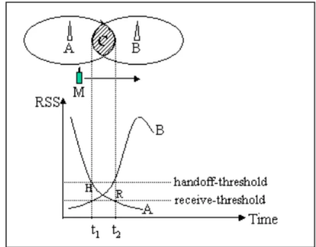
(3) RSS.. Unfortunately, if the base station which can provide a higher RSS has no. available bandwidth to handle the handoff request, the on going call will be force-terminated. The above situation is shown in Figure 1. There are two cells served by base station A and base station B.. The two cells have overlapping area C denoted by the. shaded area. Assume a mobile user M move from base station A toward base station B. The RSS from this user in base station A is decreasing (curve A in Fig. 1).. On the. other side, the RSS in base station B is increasing (curve B in Fig. 1). When the RSS in base station A is below the handoff-threshold level (point H in Fig. 1), a handoff request is sent to base station B.. Base station B will handle the handoff request from. time t1 to t2. If base station B cannot find enough available bandwidth for allocating to the mobile user M in the period and the RSS in base station A degrades to the receive-threshold level (point R in Fig. 1), the on going call of mobile user M will be force-terminated.. Figure 1. Handoff and RSS How to ensure that base station B (in Fig. 1) has enough bandwidth to handle the handoff call request has been widely discussed. section.. We will review these methods in next. In this paper, we will propose a handoff request queuing ordering scheme for. 3.
(4) multimedia wireless networks.. In our method, every base station has a handoff request. queue to line up the handoff requests. We use a priority scheme to order the mobile user’s handoff request. The remainder of this paper is organized as follows. related work.. Our method is described in Section 3.. verification are shown in Section 4.. In Section 2, we survey the The simulation model and. In Section 5, we figure out the simulation results.. Finally, Section 6 concludes this paper. 2. Related Work The researches of [5-9] indicate, from the mobile user’s point of view, forced termination of an ongoing call is clearly less desirable than blocking of a new all attempt.. In non-prioritized call handling schemes, the handoff requests are treated in. the same manner as the new call requests so that the probability of handoff failure equals the probability of call blocking.. In order to decrease the probability of handoff. call failure, there are many methods.. We classify the proposed schemes into the. following: 1) Call Admission Control Schemes 2) Guard Channel Schemes 3) Channel Reservation Schemes 4) Handoff Queuing Schemes The Call Admission Control Schemes restrict the number of new calls accepted to decrease the probability of handoff call failure.. In [10], a cell-cluster-based call. admission control strategy has been proposed to guarantee QoS as defined for each class of wireless connection.. The paper by Naghshineh and Schwartz [11] proposed a. distributed call admission control scheme that takes the number of calls in adjacent cells into consideration when making a call admission decision. 4. In [12], admission control.
(5) policy is based on a predetermined threshold value of either the mean delay or the packet loss probability for data traffic, and on the long-term blocking probability for voice traffic. An admission control scheme based on dynamic channel assignment is proposed in [13]. The shadow cluster concept has been proposed to estimate future resource requirements and to perform call admission decisions in wireless networks in [14]. Aljadhai and Znati [15] proposed a Most Likely Shadow Cluster framework to support predictive timed-QoS guarantees in wireless networks. The Guard Channel Schemes reserve a fixed or dynamically adjustable number of channels exclusively for handoff requests.. The risk for having exclusive handoff. channels is inefficient spectrum utilization. Oh and Tcha [16] suggested an analytical model which incorporates the idea of giving priority to handoff calls into channel assignment. Yoon and Un [17] presented and compared three call handling schemes for a base station to handle new calls and handoff calls.. A novel dynamic guard. channel scheme has been proposed in [18], which adapts the number of guard channels in each cell according to the current estimate of the handoff call arrival rate derived from the current number of ongoing calls in neighboring cells and the mobility pattern. Sivalingam et al. [19] investigated static and dynamic resource allocation schemes, called ExpectedMax strategy. The Channel Reservation Schemes reserve bandwidth in these cells where the mobile users are expected to visit in the near future.. If the reserved bandwidth is made. in a wrong cell, it will cause inefficient bandwidth utilization and the handoff request will be force-terminated.. Oliveira et al. [20] proposed a bandwidth allocation scheme. to allocate bandwidth to a connection in the cell where the connection request originates and reserves bandwidth in all neighboring cells. Oliver and Borras [21] takes the information reported by the mobile terminal to adaptively establish the number of 5.
(6) channels to be reserved in the target cell.. To accurately reserve bandwidth in the right. cell, there are some papers that use mobility pattern [22, 23] to predict the location of mobile users in the near future.. In [23], a novel hierarchical location prediction (HLP). algorithm has been proposed to mimic actual human behavior. Handoff Queuing Schemes discusses how to line up the handoff requests in queue at every cell.. Tekinay and Jabbari [8] presented a Measurement Based Prioritization. Scheme, MBPS, to employ a dynamic priority queuing discipline instead of FIFO.. In. [24], Ebersman and Tonguz improved the MBPS algorithm by using both RSS and the change in RSS ( ∆RSS ) to determine the priority ordering in the handoff queue. called this method Signal Prediction Priority Queuing (SPPQ).. They. In SPPQ, the value of. ∆RSS can be calculated using the following formula: ∆ RSS =. RSS t 2 − RSS t 1 t 2 − t1. In this paper, we will extend the SPPQ algorithm to handle the multimedia traffic. Our method uses the ∆RSS to offer a handoff priority value for different service classes.. The following section will discuss this method in detail.. 3. Signal Strength for Multimedia Communication Scheme If the target base station has no available bandwidth to serve, queuing the handoff request is possible because the mobile users spend some period of time in the overlapping area (as previously stated).. In this time period, the target base station. must deal with many things, which include: new call requests, other handoff call requests, call terminations and so on. Each event changes the conditions of a base station and the RSS of every handoff request is changing too. When an on going call is finished, the occupied bandwidth will be released.. Our goal is to decide who has the. highest priority to use the released bandwidth and how to line up these handoff requests. 6.
(7) in the handoff queue in a base station. In this paper, we propose a Signal Strength for Multimedia Communications Scheme, abbreviated as SSMC. SSMC offers a line up method for handoff requests in the multimedia wireless system.. In SSMC, if all channels of a base station are. occupied, the new call requests within that cell are simply blocked and the handoff requests to that cell are queued.. The SSMC uses the following schemes to line up the. handoff requests in queue. 1.. Assume there are k types of different service classes in wireless system. priority. for. the. service. 1 ≤ p1 < p2 < ⋅⋅ < pi < ⋅ ⋅ ⋅ < pk 2.. class. i. is. pi. ,. The where. for 1 ≤ i ≤ k .. In the time period t1 to t2, the ∆RSS ( j ) for the handoff request j is measured by the following formula: ∆RSS ( j ) =. RSS t 2 ( j ) − RSS t1 ( j ) t 2 − t1. 3. The handoff priority for handoff request j, with service class priority p j , is P( j ) = p j * ∆RSS ( j ) *. 1 . RSS ( j ). The value of ∆RSS is the absolute value of slope of the decreasing part of RSS curve.. It will always be greater than zero.. And for every service class i, pi is. greater than one. Also 1 / RSS ( j ) will get larger when the RSS ( j ) is getting smaller. Therefore, the handoff request j with a higher service class priority or lower RSS value will get a larger P ( j ) than other handoff requests that have the same RSS decreasing rate, ∆RSS . In SSMC, when the base station has an available bandwidth, the handoff request. 7.
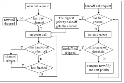
(8) with the highest handoff priority, P ( j ) , will be served first. non-preemptive dynamic priority discipline.. The SSMC method is a. The ∆RSS levels are monitored. continuously, and the priority of a handoff request dynamically changes depending on ∆RSS ( j ) and pi while waiting in the queue. The handoff requests waiting for the. bandwidth in the handoff queue are sorted continuously according to their priorities. Figure 2 shows the flowchart of SSMC working in one cell. As the figure shows, if there has no free channel in a cell, a new call request will be simply dropped and the handoff call request will be put into queue. An on going call will release the occupied channel when the call has finished or has been handed-off to a neighboring cell. The RSS level is monitored, and ∆RSS is recomputed every second [24]. When the RSS level of the handoff call request is lower than the receive-threshold level, the handoff call request will be dropped (force-terminated).. In the queuing time, the value P ( j ). of a handoff request is monitored and sorted continuously.. If there has free channel. and the handoff request has the highest priority, the handoff request gets the channel.. Figure 2. The flowchart of SSMC in one cell. In the following section, we will test our method by using simulation.. As the. simulation results shown, our method will reduce the handoff call dropped probability. 8.
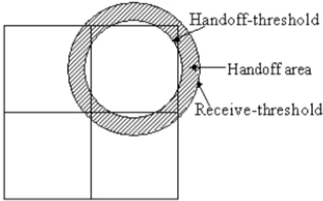
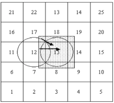
(9) effectively. 4. Simulation Model and Verification In this section, we compare the performance of SSMC strategy with other schemes. The inputs to the simulator are a model of the wireless network and the characteristics of multimedia traffic in this network.. The outputs of the simulator. include the dropping probabilities for handoff and new connection requests. As Fig. 3 shown, the network system in simulation includes twenty-five cells. The area of one cell is 4*4 kilometers. We assume the top cells (cell 21, 22, 23, 24 and 25) and the bottom cells (cell 1, 2, 3, 4 and 5) are connected. That is if a user comes out of cell 21 from top, he will come into cell 1.. Analogously, we assume the left cells. (cell 1, 6, 11, 16 and 21) and right cells (cell 5, 10, 15, 20 and 25) are connected too.. Figure 3. The simulated wireless network.. Figure 4. Handoff threshold and receive threshold Figure 4 shows the concept of handoff-threshold and receive-threshold setting. Because the shape of cell is square, we set the receive-threshold to 2.9 km, in order to. 9.
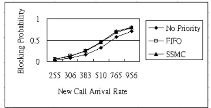
(10) cover all the cell area. cell-center. to. The handoff-threshold can be set at any distance between. receive-threshold.. The. area. between. handoff-threshold. and. receive-threshold is called handoff area (the shaded area of Fig. 4). The mean time of a handoff call spent in the handoff area is 10 seconds in simulations [8,24].. In this. situation, we set the handoff-threshold to 2.7 km (the mean time a handoff call will spend in the handoff area is 12 seconds under the mobility pattern). The user mobility pattern is described as follows.. When a new call request is. accepted, the original location of the mobile user is a random variable of the whole network system, and the moving direction is set by a random angle between 0 degree and 360 degree. The moving speed is uniformly distributed between 30 km and 90 km. We monitor the location of every user at every second and compute the RSS of each user. Table 1 shows the service classes in our simulation. The required bandwidth of the service classes is 64 Kbps, 64*2 Kbps and 64*4 Kbps respectively.. The. connection mean duration for each class is 60 seconds, 60*5 seconds and 60*15 seconds respectively.. The handoff priority for each class is 1, 4 and 8 respectively.. The channel capacity of a cell is 50*64 Kbps. We compare the handoff and new connection dropping probabilities of three different strategies.. The first strategy, labeled No priority, is a non-prioritized call. handling scheme in which a handoff request will be simply dropped if the target base station has no available channel. The second strategy, labeled FIFO, is prioritized call handling scheme in which a handoff request will be filed in the queue with first-in first-out strategy if the target base station has no free channel.. The third strategy is the. proposed SSMC strategy. We compare the results of the blocking probabilities with those computed by the 10.
(11) queuing model [25] to verify the simulation’s accuracy.. For non-prioritized call. handling scheme, the probability of handoff call dropping (Pd) equals the probability of new call blocking (Pb), which is given by the well-known Erlang B formula for the M/M/c/c queue. (cρ ) c Pb = Pd = c c! i , (cρ ) ∑ i! i =1. ρ = λ / cµ. If we limit the connection duration time to 40 seconds, the distance that a connection call moves is at most 1 km (the speed is between 30 km/hour and 90 km/hour).. This concept is illustrated by figure 5.. is λ / 25 when the whole system arrival rate is λ.. The new call arrival rate for cell 13 Besides the new call arrival rate,. cell 13 will handle the handoff requests from cells 7, 8, 9, 12, 14, 17, 18 and 19. So the total call arrival rate of cell 13 will include the new call arrival rate λ / 25 and the handoff calls from the neighboring cells. Since the call duration is 40 seconds, we extend the size of cell 13 by 1 km in each direction, which is shown in Fig. 5 by the shaded square area.. Figure 5. The call arrival rate analytical model. Under the 40 seconds connection duration constraint, a connection call in cell 12 that handoffs to cell 13 must start at the 1 km from right side cell boundary (the shaded area in cell 12). The probability that a call will start at this area is 1/4 for 4*4 km2 cell. 11.
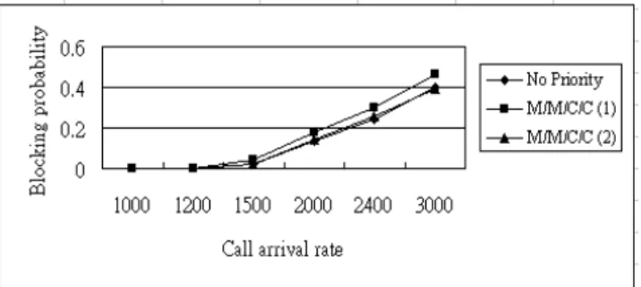
(12) Since handoff-threshold is 2.9 km from the cell center, the distance from the call starting point to the handoff-threshold boundary is 1.9 km. The probability that a connection call will request handoff is 1/1.9 at most. Because the moving direction of a mobile is uniformly distributed between 0 degree to 360 degree, the probability that a connection call will handoff to cell 13 from cell 12 is 1/4. By the above analysis, the probability that a connection call starting at cell 12 will handoff to cell 13 is 1 / 4 *1 / 1.9 *1 / 4 ≈ 1 / 32 .. The same analysis can be applied to cells 8, 14 and 18.. By a similar reasoning, the probability that a connection call starting at cell 17 (or 7, 9, 19) will handoff to cell 13 is 1 / 16 * 2 / 3 *1 / 16 . handoff request arrival rate is 13 / 96 * λ / 25 .. Adding all the probabilities, the. Figure 16 shows the call blocking. probabilities of non-prioritized scheme by simulation and the M/M/C/C results.. In this. simulation, there is only class 1 traffic and every cell has 50 channels.. Figure 6. Probability of call blocking versus offered traffic for non-prioritized call handling. In Fig. 6, M/M/C/C(1) is computed by the 13 / 96 * λ / 25 + λ / 25 call arrival rate, and M/M/C/C(2) is by λ / 25 arrival rate.. Why is the simulation results close to the. result of λ / 25 arrival rate (curve of M/M/C/C(2) in Fig. 12)? This is because there are only a few number of handoff call requests in the wireless system under the simulation condition. Even if a call needs handoff, the remaining service time in the new cell is short.. 12.
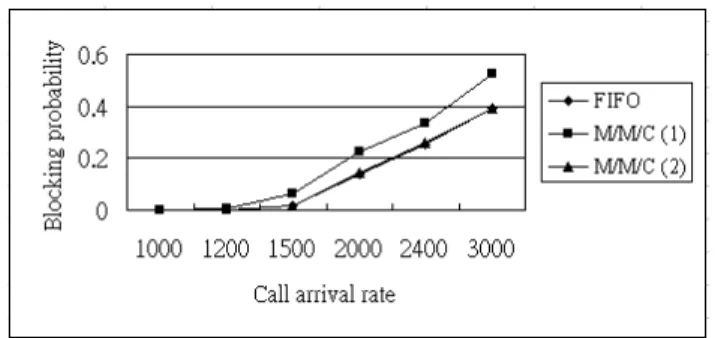
(13) The FIFO queuing scheme can be approximated by an M/M/c queue [8]. Until all channels are occupied, the arrival rate is the sum of new calls and handoff calls. Once all the channels are busy, only handoff calls are queued. The new call blocking probability of originating calls is simply given by the probability of the number of users in the system being equal to or more than the number of channels, c, i.e., ∞. Pb = ∑ pn n =c. 1 λ + λh = c c! u . c. cu p0 cµ − λh . where λc and λh stand for the arrival rates of new calls and handoffs, respectively,. c −1 1 λ + λ n 1 λ + λ c cu h h + c and po = ∑ c n=0 n! u c! u cµ − λh . −1. Fig. 7 demonstrates the accuracy of FIFO queuing method by comparing the analytical and simulation results.. In this figure, M/M/C(1) is computed by the. λc = λ / 25 and λh = 13 / 96 * λ / 25 call arrival rate, and M/M/C(2) is by λc = λ / 25 and λh =0 arrival rate.. Figure 7. Probability of new call blocking versus offered traffic for FIFO call handling. 5. Simulation Results. We illustrate the simulation results in the following paragraph.. 13. All the.
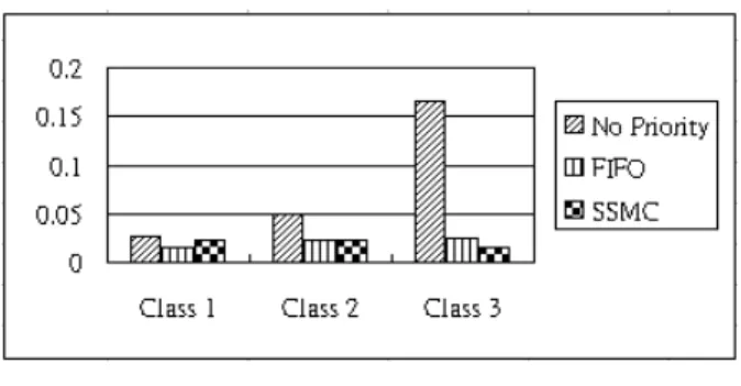
(14) simulations are done with arrival rate ratio, 40:10:1, for service classes 1, 2 and 3.. If. the new call arrival rate is 51 calls per second, there will be 40 calls of class 1, 10 calls of class 2 and 1 calls of class 3. All the results are average of 10 days.. Figures 8 and. 9 show the handoff call dropping probability and new call blocking probability where the arrival rate is 510 calls per second.. Figure 8. Handoff call dropping probability.. Figure 9. New call blocking probability. According to the above results, SSMC can reduce about 15% handoff dropping probability than non-priority method for class 3. The value of FIFO and SSMC for handoff call dropping probability of class 2 is almost equal. The dropping probability value of FIFO is small than SSMC about 0.8%; in contrast to the dropping probability value of SSMC is small than FIFO about 0.8%.. Although, the dropping probability. values seem the same, the bandwidth for class 3 is triple of class 1. So, the SSMC can efficient use the bandwidth than FIFO. Figures 10, 11 and 12 show the handoff call dropping probability of three service classes versus different new call arrival rates.. 14. It shows that the SSMC is effective in.
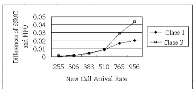
(15) reducing class 3’s handoff call dropping probability. According to the differences of handoff call dropping probability between FIFO and SSMC (FIFO minus SSMC) for class 1 and class 3, fig. 13, SSMC has outstanding efficiency in decreasing the dropping probability in high new call arrival rates,. Figure 10. Handoff call dropping probability of class 1.. Figure 11. Handoff call dropping probability of class 2.. Figure 12. Handoff call dropping probability of class 3.. Figure 13. The differences of handoff call dropping probability. 15.
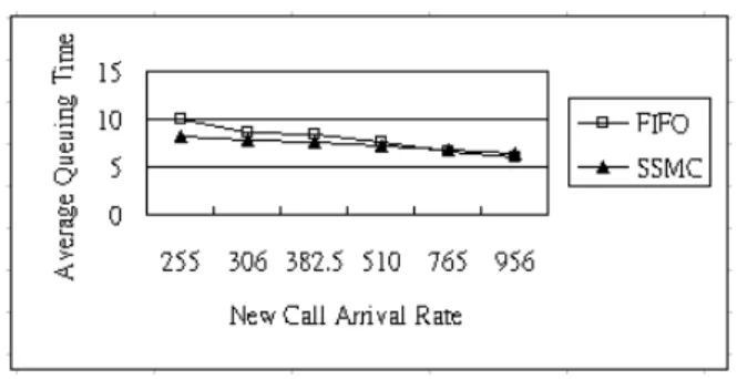
(16) Figures 14, 15 and 16 represent the new call blocking probability under different new call arrival rates.. According to these results the blocking probability of SSMC is. almost the same as that of FIFO. Note that class 3’s blocking probability is not affected as much as other classes.. Figure 14. New call blocking probability of class 1.. Figure 15. New call blocking probability of class 2.. Figure 16. New call blocking probability of class 3. The average queuing time of FIFO and SSMC is shown in Fig. 17. result shows, the SSMC has shorter handoff processing delay than FIFO.. 16. As the.
(17) Figure 17. Average queuing time versus offered load. 6. Conclusion. In wireless networks, handoff between cells is unavoidable. The probability of forced termination is the most important quality of service (QoS) parameter, which requires special method to manage the handoff requests when the micro-cells are used. There are many methods proposed to handle this problem, which include: Call Admission Control Schemes, Guard Channel Schemes, Channel Reservation Schemes and Handoff Queuing Schemes.. In this paper, we propose a Handoff Queuing Scheme,. which focuses on the problem of handoffs in a multimedia communication wireless network. A simple algorithm called SSMC is proposed, which can reduce the handoff call dropping probability in multimedia wireless network. We do a simulation in 25-cells wireless network for three service classes, and the simulation results show our method can reduce handoff call dropping probability at least 15% for high handoff priority service class. There is a tradeoff between the handoff call dropping probability and new call blocking probability. SSMC increases about 15% in new call blocking probability to have low dropping probability.. In the future, we’ll try to analyze the performance of. SSMC. Furthermore, more service classes will be simulated to test the behavior of SSMC under different conditions.. 17.
(18) REFERENCE. 1.. K. Pahlavan and A. H. Levesgue, “Wireless data communications,” Proc. IEEE, vol. 82, 1994, pp. 1398-1430.. 2.. D. J. Goodman, “Cellular packet communications,” IEEE Trans. Commun., vol. 39, Sept. 1991.. 3.. J. Sarnecki, C. Vinodrai, A. Javed. P. O’kelly, and K. Dick, “Microcell design principles,” IEEE Commun. Mag., vol. 31, Apr. 1993, pp. 76-82. 4.. W. C. Y. Lee, “Smaller cells for greater performance,” IEEE Commun. Mag., Nov. 1991, pp. 19-23.. 5.. D. Giancristofaro, M. Ruggieri, F. And Santucci, “Analysis of queue-based handover procedures for mobile communications,” Proc. IEEE ICUPC, 1993, pp. 168-172.. 6.. D. Hong, and S. S. Rappaport, “Traffic model and performance analysis for cellular mobile radio telephone systems with prioritized and nonprioritized handoff procedure,” IEEE Trans. Veh. Techol., VT-35(3), August 1986, pp.77-92.. 7.. L. R. Hu, and S. S. Rappaport, “Micro-cellular communication systems with hierarchical macrocell overlays: traffic performance models and analysis,” WINLAB Workshop, 1993, pp.143-174.. 8.. S. Tekinary, and B. Jabbari, “A measurement based prioritization scheme for handovers in cellular and micro-cellular networks,” IEEE J. Select. Areas Commun., October 1992, pp.1343-1350.. 9.. C. H. Yoon, K. and Un, “Performance of personal portable radio telephone system with and without guard channels,” IEEE J. Select. Areas Commun., vol. 11, no. 6, August 1993, pp. 911-917.. 10. S. Acapora and M. Naghshineh, “Control and quality of service provisioning in 18.
(19) high-speed micro-cellular networks,” IEEE Pers. Commun., vol. 1, no. 2, 1994. 11. M. Naghshineh and M. Schwartz, “Distributed call admission control in mobile/wireless networks,” Proc. Personal, Indoor and Mobile Radio Commun., 1995. 12. W. B. Yang and E. Geraniotis, “Admission policies for integrated voice and data traffic in CDMA packet radio networks,” IEEE J. Select. Areas Commun., vol. 12, May 1994. 13. J. Tajima and K. Imamura, “A strategy for flexible channel assignment in mobile communication systems,” IEEE Trans. Veh. Technol., vol. 37, May 1988. 14. David A. Levine, Ian F. Akyildiz and Mahmoud Naghshineh, “A resource estimation and call admission algorithm for wireless multimedia networks using the shadow cluster concept,” IEEE/ACM Trans. Networking, vol. 5, no. 1, February 1997, pp. 1-12. 15. AbdulRahman Aljadhai and Taieb F. Znati, "A framework for call admission control and QoS support in wireless environments," IEEE INFOCOM, 1999, pp. 1019-1026. 16. Se-Hyun Oh and Dong-Wan Tcha, “Prioritized channel assignment in cellular radio network,” IEEE Trans. Commun., vol. 40, no. 7, July 1992, pp. 1259-1269. 17. Chong Ho Yoon and Chong Kwan Un, “Performance of personal portable radio telephone systems with and without guard channels,” IEEE J. Select. Areas Commun., vol. 11, no. 6, August 1993, pp. 911-917. 18. . Oliver T. W. Yu and Victor C. M. Leung, "Adaptive resource allocation for prioritized call admission over an ATM-Based Wireless PCN," IEEE J. Select. Areas Commun., vol. 15, no. 7, September 1997, pp. 1208-1225. 19. Krishna M. Sivalingam, Prathima Agrawal and Shalinee Kishore, "Dynamic 19.
(20) resource allocation schemes during handoff for mobile multimedia wireless networks," IEEE J. Select. Areas Commun., vol. 17, no. 7, July 1999, pp. 1270-1283. 20. Carlos Oliveira, Jaime Bae Kim and Tatsuya Suda, "An adaptive bandwidth reservation scheme for high-speed multimedia wireless networks," IEEE J. Select. Areas Commun., vol. 16, no. 6, August 1998, pp. 858-873. 21. Miquel Oliver, Joan Borras, "Performance evaluation of variable reservation policies for hand-off prioritization in mobile networks," IEEE INFOCOM, 1999, pp. 1187-1194. 22. Mahmood M. Zonoozi and Prem Dassanayake, "User mobility modeling and characterization of mobility patterns," IEEE J. Select. Areas Commun., vol. 15, no. 7, Sept. 1997, pp. 1239-1252. 23. Tong Liu, Paramvir Bahl and Imrich Chlamtac, "Mobility modeling, location tracking, and trajectory prediction in wireless ATM networks," IEEE J. Select. Areas Commun., vol. 16, no. 6, August 1998, pp. 922-936. 24. Howard G. Ebersman and Ozan K. Tonguz, "Handoff ordering using signal prediction priority queuing in personal communication system," IEEE Trans. Veh. Technol., vol. 48, No. 1, January 1999, pp. 20-35. 25. L. Kleinrock, Queuing Systems, vol. 1, New York: Wiley, 1975.. 20.
(21)
數據
+7
相關文件
Overview of a variety of business software, graphics and multimedia software, and home/personal/educational software Web applications and application software for
request even if the header is absent), O (optional), T (the header should be included in the request if a stream-based transport is used), C (the presence of the header depends on
• Apply to EDB for exemption from the requirement to adopt eligibility criteria for fee remission scheme no less favorable than those of government financial assistance schemes,
• Learn about wireless communications and networks!. • Why is it so different from wired communications
• When the coherence bandwidth is low, but we need to use high data rate (high signal bandwidth). • Channel is unknown
• When the coherence bandwidth is low, but we need to use high data rate (high signal bandwidth). • Channel is unknown
The AR part is designated for the desired adjustment to the target; the exogenous part is corresponding the offset between the center of target and the aiming point wherein
For MIMO-OFDM systems, the objective of the existing power control strategies is maximization of the signal to interference and noise ratio (SINR) or minimization of the bit
