Energy losses of charged particles moving parallel to the surface of an overlayer
system
C. M. Kwei, S. J. Hwang, Y. C. Li, and C. J. Tung
Citation: Journal of Applied Physics 93, 9130 (2003); doi: 10.1063/1.1569974 View online: http://dx.doi.org/10.1063/1.1569974
View Table of Contents: http://scitation.aip.org/content/aip/journal/jap/93/11?ver=pdfcov
Published by the AIP Publishing
Articles you may be interested in
Energy loss rate of a charged particle in HgTe/(HgTe, CdTe) quantum wells
Appl. Phys. Lett. 103, 192107 (2013); 10.1063/1.4829467
A reverse Monte Carlo method for deriving optical constants of solids from reflection electron energy-loss spectroscopy spectra
J. Appl. Phys. 113, 214303 (2013); 10.1063/1.4809544
Influence of a strong laser field on Coulomb explosion and stopping power of energetic H 3 + clusters in plasmas
Phys. Plasmas 19, 093116 (2012); 10.1063/1.4752417
Hot Electron Energy Loss Rate in GaN/AlGaN Heterosructures
AIP Conf. Proc. 1349, 929 (2011); 10.1063/1.3606162
Retardation effect on energy losses of electrons moving parallel to solid surfaces
J. Appl. Phys. 100, 103703 (2006); 10.1063/1.2375013
Energy losses of charged particles moving parallel to the surface
of an overlayer system
C. M. Kwei,a) S. J. Hwang, and Y. C. Li
Department of Electronics Engineering, National Chiao Tung University, Hsinchu 300, Taiwan
C. J. Tung
Department of Nuclear Science, National Tsing Hua University, Hsinchu 300, Taiwan
共Received 22 November 2002; accepted 6 March 2003兲
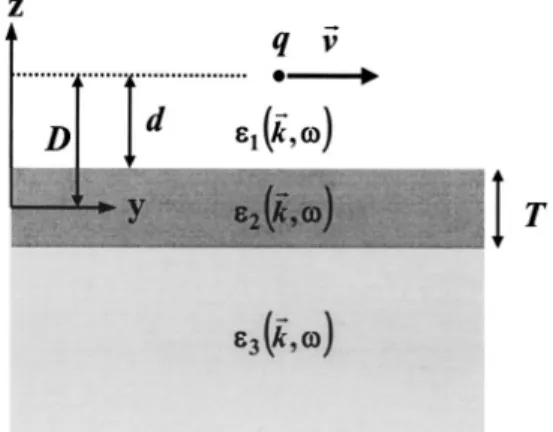
An energetic charged particle moving parallel to the surface of an overlayer system was studied. This system was composed of a thin film on the top of a semi-infinite substrate. Based on the dielectric response theory, the induced potential was formulated by solving the Poisson equation and matching the boundary conditions. The stopping force was built-up using the energy-momentum conservation relations and the extended Drude dielectric functions with spatial dispersion. Surface 共vacuum–film兲 and interface 共film–substrate兲 excitations were included in the formulations of the interaction between charged particles and the overlayer system. Results of the wake potential were presented for protons moving parallel to a vacuum–copper–silicon system. Dependences of the induced potential and the stopping force on film thickness, distance of the proton from surface, and proton velocity were investigated. © 2003 American Institute of Physics.
关DOI: 10.1063/1.1569974兴
I. INTRODUCTION
Many experimental and theoretical studies have been performed on the various aspects of the interaction between fast charged particles and solid surfaces. Theoretical approaches1–3 were developed for the evaluation of the in-duced potential caused by charged particles traveling outside a solid and parallel to its surface. This potential arose from the dielectric response of the solid and led to, mainly, surface plasmon excitations. Theoretical calculations of surface ex-citations were made in earlier works.4,5The surface response was characterized in terms of the dielectric function of the bulk material. Several models and approximations of the di-electric function6 – 8were developed.
A study of the induced potential in an overlayer system 共film on substrate兲 is important when dealing with the pro-duction of electrons by swift ions and with the transport of convoy electrons on their emission9,10 and acceleration.11,12 In such a study, it is required to provide data on the induced potential and the stopping force for charged particles. Thus certain procedures have to be established in order to make accurate predictions of these quantities. The purpose of this work was to derive a model treatment of the induced poten-tial for charged particles moving outside an overlayer system and parallel to its surface 共vacuum–solid兲 and interface 共film–substrate兲. The interaction of charged particles with the overlayer system includes not only surface excitations but also interface excitations. Models developed for the semi-infinite solids should not be applied directly to the overlayer system.
Previously, a model13,14 of the energy loss probability was constructed for an overlayer system by several authors.
Integration over the normal component of the momentum transfer was carried out using cylindrical coordinates. This model, however, did not completely satisfy the conservation constraints in energy and momentum. In order to satisfy these constraints, we applied in this work spherical coordi-nates in the momentum integration. Moreover, the induced potential was derived by solving the Poisson equation using methods of image charges and extended Drude dielectric functions with spatial dispersion.15 The image charge was external to the region of interest and used to simulate the required boundary conditions. The inclusion of dispersion was important in the region of short distances from the sur-face and the intersur-face, where charged particles might couple to short-wavelength modes of the overlayer system.1The di-electric function used in this work was a generalization of the Drude dielectric function by allowing each subband to have its own oscillator strength, damping constant, and critical point energy. All parameters in the dielectric function were properly chosen to fit optical data and to meet sum-rule re-quirements. This function was successfully employed to de-scribe the response of a semi-infinite solid and an overlayer system for penetrating electrons.16 –21
In this work, we have calculated the induced potential and the electric field for protons moving parallel to the sur-face of an overlayer system composed of a thin Cu film on the top of a semi-infinite Si substrate. Since surface excita-tions involved electrons within a few angstroms beneath the surface, we considered here films of a few angstrom thick-ness in the overlayer system to illustrate its surface and in-terface effects. Atomic units 共a.u.兲 are used throughout this article unless otherwise specified.
II. THEORY
Figure 1 illustrates the problem studied in this work, i.e., a particle of charge q and velocity v moving parallel to the a兲Electronic mail: [email protected]
9130
0021-8979/2003/93(11)/9130/7/$20.00 © 2003 American Institute of Physics [This article is copyrighted as indicated in the article. Reuse of AIP content is subject to the terms at: http://scitation.aip.org/termsconditions. Downloaded to ] IP:
surface of an overlayer system composed of a thin film on the top of a semi-infinite substrate. To simplify theoretical derivations, we let the origin of coordinates be the center of the film having thickness T and dielectric function2(k,).
The vacuum and substrate, characterized by their dielectric functions 1(k,) and 3(k,w), are in regions of z⬎T/2
and z⬍⫺T/2, where the z axis is perpendicular to the inter-face planes and directed from substrate to film. The particle, with a z coordinate equal to D, is moving in the vacuum along the y direction.
For z⬎T/2, the potential is due to the actual charge and a fictitious charge near the surface just outside the region of interest. For z⬍T/2, the potential is a solution of the Laplace
equation without singularities since there is no charge there. In the latter region, the simplest assumption is that the po-tential is contributed by an image charge q at the position of the actual charge and by fictitious charges near the interfaces. These fictitious charges should satisfy the required boundary conditions. Thus Poisson equations in the Fourier space are
1共k,兲⫽ 4 k21共k,兲
冋
f共k,兲 ⫹exp冉
⫺ikzT 2冊
s1共K,兲册
共1兲 for z⬎T/2, 2共k,兲⫽ 4 k22共k,兲冋
f共k,兲 ⫹exp冉
⫺ik2zT冊
s2⫹共K,兲 ⫹exp冉
ikzT 2冊
s2⫺共K,兲册
共2兲 for ⫺T/2⬍z⬍T/2, and 3共k,兲⫽ 4 k23共k,兲冋
f共k,兲⫹exp冉
ikzT 2冊
s3共k,兲册
共3兲 for z⬍⫺T/2, where k⫽(kx,ky,kz)⫽(K,kz) is the momen-tum transfer, is the energy transfer, and the Fourier trans-form of the charge density distribution of the moving particle is given byf共k,兲⫽2q␦共⫺kyv兲exp共⫺ikzD兲. 共4兲
The induced charges s1(K,), s2⫹(K,), s2⫺(K,), and
s3(K,) are required to satisfy the boundary conditions. By
matching potentials and displacement vectors at the inter-faces, we have s1共K,兲⫽2q␦共⫺kyv兲
再
12共T/2,D,K,兲关e⫺KT⫺32共⫺T/2,K,兲兴⫺32共⫺T/2,D,K,兲关1⫺e⫺KT12共T/2,K,兲兴 12共T/2,K,兲32共⫺T/2,K,兲⫺1冎
, 共5兲 s2⫹共K,兲⫽2q␦共⫺kyv兲冋
12共T/2,D,K,兲32共⫺T/2,K,兲⫺32共⫺T/2,D,K,兲 12共T/2,K,兲32共⫺T/2,K,兲⫺1册
, 共6兲 s2⫺共K,兲⫽2q␦共⫺kyv兲再
12共T/2,D,K,兲⫺32共⫺T/2,D,K,兲12共T/2,K,兲 12共T/2,K,兲32共⫺T/2,K,兲⫺1冎
, 共7兲 and s3共K,兲⫽2q␦共⫺kyv兲再
32共⫺T/2,D,K,兲关e⫺KT⫺12共T/2,K,兲兴⫺12共T/2,D,K,兲关1⫺e⫺KT32共⫺T/2,K,兲兴 12共T/2,K,兲32共⫺T/2,K,兲⫺1冎
, 共8兲FIG. 1. A sketch of the problem studied in this work. A particle with charge
q and velocityv, in y direction, moving in vacuum共medium 1兲 and parallel
to the surface of an overlayer system. This system is composed of a film
共medium 2兲 of thickness T on top of a substrate 共medium 3兲. The particle is
at distance D from the midplane of the film, or at distance d from the surface of the film.1,2, and3are, respectively, dielectric functions of
media 1, 2, and 3.
9131 J. Appl. Phys., Vol. 93, No. 11, 1 June 2003 Kweiet al.
where ab共⫾T/2,D,K,兲 ⫽ 1 ¯a共⫾T/2,⫺D,K,兲 ⫺ 1 ¯b共⫾T/2,⫺D,K,兲 e⫺QT 1 ¯a共K,兲 ⫺ 1 ¯b共⫾T,K,兲 , 共9兲 ab共⫾T/2,K,兲⫽ 1 ¯a共K,兲 ⫹ 1 ¯b共K,兲 e⫺QT 1 ¯a共K,兲 ⫺ 1 ¯b共⫾T,K,兲 , 共10兲 1 ¯L共K,兲 ⫽
冕
⫺⬁ ⬁ dkz k2冉
1 L共k,兲冊
, 共11兲 and 1 ¯L共l,K,兲 ⫽冕
⫺⬁ ⬁ dkz k2冉
1 L共k,兲冊
exp共ikzl兲 共12兲for a⫽1 and 3, b⫽2, and L⫽1, 2, and 3. Substituting Eqs. 共5兲–共12兲 into Eqs. 共1兲–共3兲, we obtain the scalar potentials in the Fourier space, i.e., 1(k,), 2(k,), and 3(k,).
The induced scalar potentials in the spatial space are then obtained by the inverse Fourier transforms after removing the vacuum potential of the particle from the scalar poten-tials. The induced potentialind(1)(r,t) for z⬎T/2 is of special interest since the particle is moving in vacuum. Taking 1
⫽1, we obtain ind (1)共r,t兲⫽
冕
⫺⬁ ⬁ d 2冕
⫺⬁ ⬁ d3k 共2兲3 4 k2 ⫻冋
exp冉
⫺ikzT 2冊
s1共K,兲册
exp关i共k•r⫺t兲兴. 共13兲 Because of the weak dependence of on kzas comparedto the rest of k components in the integral, one may assume (k,)⫽(K,). The same assumption was adopted by Yubero et al.22,23in the analysis of reflection-electron energy loss spectra and Kwei et al.20 in the calculation of electron elastic backscattering spectra. Using this assumption, the in-duced potential in vacuum is obtained by performing the integration over momentum transfer in Eq.共13兲 with spheri-cal coordinates as ind (1)共r,t兲⫽ q 22
冕
⫺⬁ ⬁ d冕
0 ⬁ dk冕
0 d冕
0 2 d• sin •␦共⫺kv sinsin兲共T,d,K,兲 ⫻exp兵i关xk sincos⫹共y⫺vt兲k⫻sinsin⫹共z⫺T/2兲k cos兴其, 共14兲
where r⫽(x,y,z), d⫽D⫺T/2, and
共T,d,K,兲⫽e⫺dK
再
2共K,兲⫺1 2共K,兲⫹1冋
1⫺3共K,兲⫺2共K,兲 3共K,兲⫹2共K,兲 e⫺2TK册
1⫹3共K,兲⫺2共K,兲 3共K,兲⫹2共K,兲 2共K,兲⫺1 2共K,兲⫹1 e⫺2TK ⫹ 3共K,兲⫺2共K,兲 3共K,兲⫹2共K,兲冋
e⫺TK⫹2共K,兲⫺1 2共K,兲⫹1 e⫺3TK册
1⫹3共K,兲⫺2共K,兲 3共K,兲⫹2共K,兲 2共K,兲⫺1 2共K,兲⫹1 e⫺2TK冎
. 共15兲In the above derivations, we have adopted (K,) ⫽(K,).
We now expand the␦function in Eq.共17兲 as follows:
␦共⫺kv sinsin兲⫽ 1
冑
共kv sin兲2⫺2 ⫻再
␦冉
⫺sin⫺1 kv sin冊
⫹␦冋
⫺冉
⫺sin⫺1 kv sin冊册冎
共16兲 for sin⫺1(/kv)⬍⬍关⫺sin⫺1(/kv)兴. After integrating over in Eq.共17兲 and applying (K,⫺)⫽*(K,), this equa-tion becomes ind (1)共r,t兲⫽4q 2冕
0 ⬁ d冕
0 ⬁ dk ⫻冕
sin⫺1共/kv兲 /2dsincos关k共z⫺T/2兲cos兴
冑
共k sin兲2⫺2 ⫻cos冉
x冑
共kv sin兲 2⫺2 v冊
⫻再
Re关共T,d,K,兲兴cos冋
共y⫺vt兲 v册
⫺Im关共T,d,K,兲兴sin
冋
共y⫺vt兲v册冎
. 共17兲 Applying the conservation relations of energy and momen-tum, the upper and lower limits of k are given bykmax⫽
冑
2 M E⫹冑
2 M E⫺2Mand
kmin⫽
冑
2 M E⫺冑
2 M E⫺2M,where M is the mass of the moving particle. Substituting the upper limit of integration in by E⫽Mv2/2, we obtain
ind (1) 共r,t兲 ⫽4q2
冕
0 E d冕
kmin kmax dk冕
/v k dKK cos关共z⫺T/2兲冑
k 2⫺K2兴 k冑
k2⫺K2冑
共vK兲2⫺2 ⫻cos冉
x冑
共vK兲 2⫺2 v冊
再
Re关共T,d,K,兲兴 ⫻cos冉
共y⫺vt兲v
冊
⫺Im关共T,d,K,兲兴sin冉
共y⫺vt兲 v冊冎
共18兲 after changing the variable from to K according to K ⫽k sin. Let 2 be the dielectric function of the substrate
and T⫽0, we obtain the induced potential in vacuum for a semi-infinite solid. As Ritchie et al. have pointed out,24 the present classical picture is applicable in the context of the first Born approximation quantum theory with the applica-tion of the energy-momentum conservaapplica-tion relaapplica-tions. This was explicitly explored in the derivation of the interaction between a moving charge and an electron gas.25
To compare with the corresponding expression by other authors without considering the energy-momentum conser-vation, no integration limits in momentum transfer are per-formed. Thus it is more convenient to carry out the integra-tion in momentum of Eq.共13兲 using cylindrical coordinates instead of spherical coordinates. For a semi-infinite solid, i.e., T⫽0 and 2⫽3⫽, we find
ind (1)共r,t兲⫽⫺ q v2
冕
⫺⬁ ⬁ d冕
兩兩/v ⬁ dK 1冑
K2⫺共/v兲2 ⫻exp关⫺共兩z兩⫹d兲K兴冋
共K,共K,兲⫺1兲⫹1册
⫻cos冉
冑
共Kv兲 2⫺2 v x冊
exp冋
i v共y⫺vt兲册
. 共19兲 Taking x⫽0 and neglecting the spatial dispersion, we obtain the same results as those of Arista.3Now, the stopping force is related to the derivative of
ind (1)
(r,t) at the position of the particle r0⫽(0,vt,D). For the
case of an overlayer system, we obtain
⫺dW ds ⫽⫺ 4q2 v2
冕
0 E d冕
kmin kmax dk冕
w/v k dK ⫻ K cos关d冑
k 2⫺K2兴 k冑
k2⫺K2冑
共vK兲2⫺2Im关共T,d,K,兲兴. 共20兲 The model response function used in this work is the extended Drude dielectric function.15 This function may be expressed as 共k,兲⫽b⫹兺
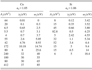
j Aj 2⫺共 j⫹k2/2兲2⫹i␥j , 共21兲where Aj, ␥j, and j are, respectively, the oscillator
strength, damping constant, and critical-point energy, all as-sociated with the jth subband. The inclusion of a background dielectric constant, b, is to account for the influence of
polarized ion cores.26All these parameters are determined by a fit of the imaginary part of the dielectric function, Im关(0,)兴, to experimental optical data. To assure the ac-curacy of the fitting parameters, we require that the fitted dielectric function satisfy the sum rules.
FIG. 2. A plot of the real and imaginary parts of the surface response function, in optical limit, vs energy transferfor a vacuum–Cu system. The solid curve is results calculated using the extended Drude dielectric func-tions with parameters listed in Table I. The dotted curve is deduced from measured optical data共Ref. 27兲.
TABLE I. Values of parameters in Eq.共21兲 for Cu and Si. Cu ⑀b⫽1.05 Si ⑀b⫽1.06 Aj(eV 2
) ␥j(eV) j(eV) Aj(eV2) ␥j(eV) j(eV)
64 0.01 0 8 0.12 3.42 20 0.1 0.3 15 0.35 3.52 6.5 0.65 2.5 45 0.66 3.80 5.5 0.7 3.1 82.8 0.5 4.25 4 0.7 3.7 5 2.42 4.55 55 2.6 5.05 32 1.1 5.34 42 4.76 8.93 52 3.4 6.4 172 10.18 14.74 15 5 9.4 80 8 25.6 15 6.5 14 240 32 40 6 5 18.4 100 30 55 80 30 65 412 37 85 9133 J. Appl. Phys., Vol. 93, No. 11, 1 June 2003 Kweiet al.
III. RESULTS AND DISCUSSION
We consider an overlayer system composed of a thin Cu film on a Si substrate. Parameters used in our calculations for the dielectric functions of Cu and Si are listed in Table I. Figure 2 shows the real and imaginary parts of the surface response function for a vacuum–Cu surface, i.e., 关2(0,)
⫺1兴/关2(0,)⫹1兴 , versus energy transfer . Figure 3
shows a similar plot of the interface response function for a Cu–Si interface, i.e., 关3(0,)⫺2(0,)兴/关3(0,) ⫹2(0,)兴 . Here 2(0,) and3(0,) are dielectric
func-tions of Cu and Si in the long-wavelength limit, i.e., k→0. In both figures, the solid curves are results calculated using the extended Drude dielectric functions. The dotted curves are corresponding results deduced from measured optical data.27 It is seen that the present results and optical data are in good agreement, despite some deviation in magnitude at the peaks in Fig. 3. Our fitting strategy is that we require both the real and imaginary parts of the dielectric function to satisfy sum rules and to exhibit and match energy loss peaks for plasmon excitations and interband transitions. We also require that fitting results agree with optical data at a broad range of
energy transfers. With this strategy, we are confident with the validity of fitting results regarding the energy losses in plas-mon excitations and interband transitions. However, due to the limited optical data it is difficult to adjust fitting param-eters to match fitting results to measured data at all energy transfers. The difference induced by this difficulty is magni-fied at peaks in the interface response function. However, such a difference makes little influence on the calculation of the induced potential and the stopping force studied in this work.
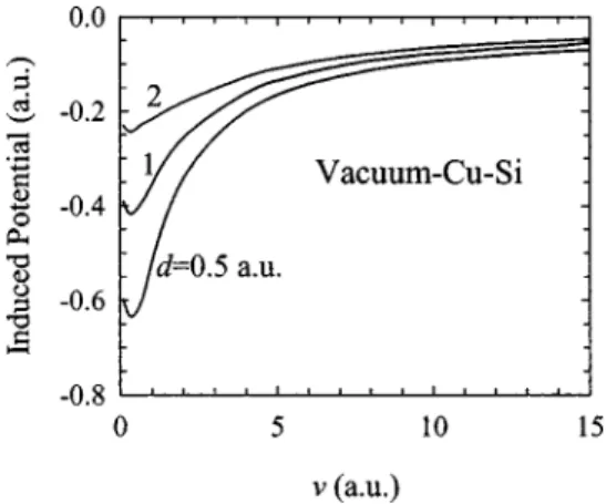
Based on Eqs.共15兲 and 共18兲 we have calculated the in-duced potential for a proton moving parallel to the surface of a vacuum–Cu–Si overlayer system. This potential at the po-sition of the proton is plotted in Fig. 4 as a function of proton velocity for several proton distances, d⫽0.5, 1, and 2 a.u., from the Cu film of thickness T⫽2 a.u. Note that the mag-nitude of this potential decreases with increasing velocity and saturates at very large velocities. In all cases, there are dips aroundv⭐1 a.u. As the distance of the proton from the
Cu film becomes smaller the dip is deeper, a similar behavior observed for a slow proton moving parallel to the surface of a semi-infinite solid with plasmon-pole dielectric functions.2 These dips occur at the threshold velocity for the creation of surface plasmons. For velocities smaller than the threshold velocity, only single electron–hole excitations occur. Our calculations of the induced potential at the position of a pro-ton for a fixed distance from the Cu film of different thick-nesses indicate that the dependence of this potential on film thickness is quite small.
Figure 5 illustrates the induced potential at points along the projection of the trajectory of a proton on the surface (z⫽T/2) and at a distance y⫺vt from the proton. Here we plot results for Cu films of thickness T⫽0, 2, and ⬁ a.u. Note that y is the coordinate of the point along the projection of the proton on the surface. The proton is moving with velocityv⫽5 a.u. at a fixed distance, d⫽1 a.u., from the Cu
surface. The instantaneous proton position is y⫽vt and z ⫽1⫹T/2. The induced potential reveals an oscillational be-havior at points behind (y⬍vt) the position of the proton. FIG. 3. A plot of the real and imaginary parts of the interface response
function, in optical limit, vs energy transferfor a Cu–Si system. The solid curve is results calculated using the extended Drude dielectric functions with parameters listed in Table I. The dotted curve is deduced from mea-sured optical data共Ref. 27兲.
FIG. 4. Velocity dependence of the induced potential at the position of the proton moving parallel to a vacuum–Cu–Si overlayer system. The proton is at distance d⫽0.5, 1 and 2 a.u. from the surface of the Cu film 共thickness T⫽2 a.u.).
FIG. 5. The induced potential at points along the projection of the trajectory of the proton on the surface and at a distance y⫺vt from the proton. Here we plot results for a vacuum–Cu–Si overlayer system with different Cu film thickness T. The proton is moving with velocityv⫽5 a.u. parallel to and at
distance d⫽1 a.u. from the Cu surface. This potential indicates oscillations behind the position of the proton.
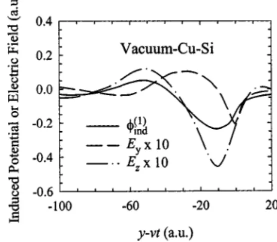
The influence of damping in the plasma modes on the in-duced potential is weak in the vacuum side. The gradual change in amplitude of this oscillation for different Cu films indicates a contribution from interface effects. Such a poten-tial approaches that of a semi-infinite Si system (T⫽0) as Cu film thickness decreases. On the other hand, it approaches to that of a semi-infinite Cu system (T⫽⬁) as Cu film thick-ness increases. Figure 6 shows the induced potential,ind(1), and the electric field components, Eyand Ez, at points along
the particle trajectory (z⫽d⫹T/2) in front of (y⬎vt) and behind (y⬍vt) the proton. Here the proton is moving with velocity v⫽5 a.u. and at a distance d⫽1 a.u. from the Cu
film of thickness T⫽2 a.u. It is seen that the induced poten-tial has a shape of the wake potenpoten-tial. Ez and Ey oscillate,
respectively, in phase and out of phase with the induced po-tential.
The dependence of the stopping force on proton velocity is illustrated in Fig. 7. Here we show the stopping force 共solid curves兲 for a proton moving at a distance d⫽2 a.u.
from the Cu films of thickness T⫽0, 1.5, and 4 a.u. The results of Arista共dotted curve兲 for a semi-infinite Cu system are included for comparison. Our results show a gradual change in the stopping force for varying thickness of Cu films. For T⫽4 a.u., the stopping force tends to approach that of a semi-infinite Cu system. In such a case, the lower values in the stopping force at small velocities found in this work are due to the constraints of energy-momentum conser-vation law. Notice that the maxima in Fig. 7 appear at a velocity around 1.5 a.u. and the stopping force drops to zero in the static limit. The existence of a maximum in the stop-ping force was also found by other theoretical models for a semi-infinite system.3The present work also reveals that the stopping force increases as proton distance decreases, a con-sequence due to the increased magnitude in the induced po-tential.
IV. CONCLUSIONS
A dielectric response theory was used to describe the inelastic interactions between a charged particle and an over-layer system in the case of a parallel trajectory. In this theory, the response of the overlayer system was composed of sur-face and intersur-face excitations and characterized in terms of dielectric functions of the film and the substrate. An ex-tended Drude dielectric function was employed by the inclu-sion of the spatial disperinclu-sion effect. This function was built-up from measured optical data. The quantum effect of the moving particle was incorporated into the dielectric theory by considering the recoil effect. This effect was in-cluded by applying the conservation laws of energy and mo-mentum. In this work, we have applied the continuum dielec-tric model to the overlayer system composed of a thin film and a substrate. The application of the model in the case of a thin film alone might be questionable. The validity of the model for an overlayer system was based on the continuum properties of the system and the inclusion of surface and interface charges and modifications.
Applying the method of image charges, analytical for-mulas have been derived for the calculation of the stopping force and the induced potential for charged particles moving parallel to the surface of an overlayer system. These formu-las could be applied to any particles and overlayer systems. The approach could also be applied, in general, to any par-allel trajectories inside and outside the solids. However, in the case of velocities smaller than the threshold of generating surface plasmons, only single particle–hole excitations con-tribute to the energy loss.2,28 In such a case, it may be nec-essary to use the local-field-correction random-phase-approximation29instead of the Drude model to calculate di-electric functions.
An energetic charged particle moving parallel to the sur-face of an overlayer system was studied. Calculated results of the induced potential and the stopping force were pre-sented for protons moving parallel to a vacuum–copper– silicon system. Corresponding experiments are, however, dif-ficult due to the actual size and the bending of a beam. In such experiments, the beam size must be confined to a few angstroms. Otherwise, the surface and interface effects will FIG. 6. The induced potential and electric field components at points along
the trajectory of proton and at a distance y⫺vt from the proton for a vacuum–Cu–Si overlayer system. The proton is moving with velocityv
⫽5 a.u. parallel to and at distance d⫽1 a.u. from the surface of the Cu film
of thickness T⫽2 a.u.
FIG. 7. Velocity dependence of the stopping force for a proton moving parallel to and at a distance d⫽2 a.u. from the surface of Cu films of dif-ferent thicknesses in the vacuum–Cu–Si overlayer system. The solid curves are the results of present calculations. The dotted curve is the data of Arista
共Ref. 3兲 for a semi-infinite Cu system.
9135 J. Appl. Phys., Vol. 93, No. 11, 1 June 2003 Kweiet al.
be averaging out and diminish. Because the induced potential or the stopping force decreases as particle velocity increases, as can be seen in Figs. 4 and 7, a fast particle is better than a slow particle for experimental measurements.
ACKNOWLEDGMENT
This research was sponsored by the National Science Council of the Republic of China under Contract No. NSC 90-2218-E-009-042.
1
F. J. Garcı´a de Abajo and P. M. Echenique, Phys. Rev. B 46, 2663共1992兲.
2
F. J. Garcı´a de Abajo and P. M. Echenique, Phys. Rev. B 48, 13399共1993兲.
3N. R. Arista, Phys. Rev. A 49, 1885共1994兲. 4R. H. Ritchie, Phys. Rev. 106, 874共1957兲.
5R. H. Ritchie and A. L. Marusak, Surf. Sci. 4, 234共1966兲. 6
F. Bloch, Z. Phys. 81, 363共1933兲.
7B. I. Lundqvist, Phys. Status Solidi 32, 273共1969兲.
8J. Lindhard, K. Dan. Vidensk. Selsk. Mat. Fys. Medd. 28, 1共1954兲. 9J. Burgdo¨rfer, Nucl. Instrum. Methods Phys. Res. B 67, 1共1992兲. 10P. Focke, S. Sua´rez, R. Pregliasco, and W. Mekbach, Nucl. Instrum.
Meth-ods Phys. Res. B 67, 1共1992兲.
11T. Iitaka, Y. H. Ohtsuki, A. Koyama, and H. Ishikawa, Phys. Rev. Lett. 65,
3160共1990兲.
12K. Kimura, M. Tsuji, and M. Mannami, Phys. Rev. A 46, 2618共1992兲.
13P. E. Batson, Ultramicroscopy 11, 299共1983兲. 14
A. Howie and R. H. Milne, Ultramicroscopy 18, 427共1985兲.
15C. M. Kwei, Y. F. Chen, C. J. Tung, and J. P. Wang, Surf. Sci. 293, 202
共1993兲.
16C. J. Tung, Y. F. Chen, C. M. Kwei, and T. L. Chou, Phys. Rev. B 49,
16684共1994兲.
17
Y. F. Chen, P. Su, C. M. Kwei, and C. J. Tung, Phys. Rev. B 50, 17547
共1994兲.
18Y. F. Chen, C. M. Kwei, and P. Su, J. Phys. D 28, 2163共1995兲. 19
C. M. Kwei, P. Su, Y. F. Chen, and C. J. Tung, J. Phys. D 30, 13共1997兲.
20C. M. Kwei, S. Y. Chiou, and Y. C. Li, J. Appl. Phys. 85, 8247共1999兲. 21C. M. Kwei, S. S. Tsai, and C. J. Tung, Surf. Sci. 473, 50共2001兲. 22F. Yubero and S. Tougaard, Phys. Rev. B 46, 2486共1992兲.
23F. Yubero, J. M. Sanz, B. Ramskov, and S. Tougaard, Phys. Rev. B 53,
9719共1996兲.
24R. H. Ritchie et al., in Physical and Chemical Mechanisms in Molecular
Radiation Biology, edited by W. A. Glass and N. V. Varma共Plenum, New
York, 1991兲, p. 99.
25
F. Flores, in Interaction of Charged Particles with Solids and Surfaces, edited by A. Gras-Marti, H. M. Urbassek, N. R. Arista, and F. Flores
共Plenum, New York, 1991兲, p. 3.
26D. Y. Smith and E. Shiles, Phys. Rev. B 17, 4689共1978兲.
27E. D. Palik, Handbook of Optical Constants of Solids I共Academic, New
York, 1985兲.
28C. M. Kwei, J. J. Chou, J. Yao, and C. J. Tung, Phys. Rev. A 64, 042901
共2001兲.
29K. Utsumi and S. Ichimaru, Phys. Rev. A 26, 603共1982兲.