ISCAS 2000
-
IEEE International Symposium on Circuits and Systems, May 28-31, 2000, Geneva, SwitzerlandA PARAMETRIC MODULE DESIGN FRAMEWORK AND
ITS APPLICATION TO GATE-LEVEL DATAPATWDSP MODULE SYNTHESIS
Ming-Luen Liou and Tzi-Dar Chiueh
Department
of
Electrical Engineering
National Taiwan University, Taipei, Taiwan R.0.C
chiueh@cc.ee.ntu.edu.tw
ABSTRACT
The paper presents a parametric module design framework that is suitable for datapatNDSP soft-IP design. This framework is based on the integration of various frequently used parametric module generators. Under this design framework, system or circuit design- ers specify the structural information of the modules in C++, and then compile and co-simulate with any C/C++ programs/algorithms. Furthermore, they can manually adjust the simulation model when- ever necessary. Once the system design is completed, an efficient gate-level Verilog code can soon be generated automatically. By examining the system functionality using high-level language and automatically translating the design entries into gate-level descrip- tion, we can easily keep our design effort at system level while maintaining a tight consistency between different levels of abstrac- tion. Therefore the proposed framework yields a fast, robust, and cost-effective solution to high-complexity datapath/DSP module design.
1. INTRODUCTION
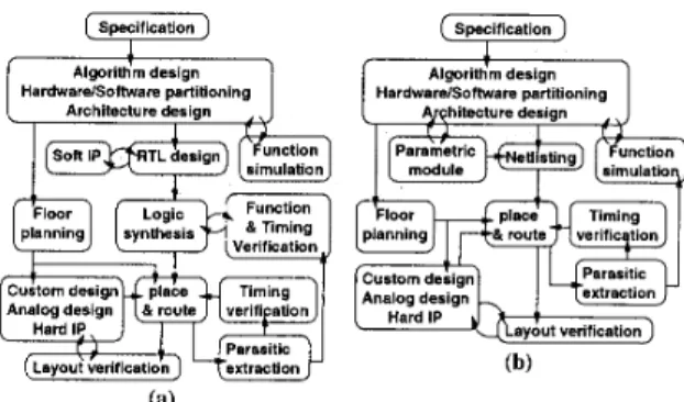
Rapid advancement in VLSI technologies today makes the sys- tem on chip(SoC) design more and more feasible. Many EDA tools, such as integrated design environments and enhanced de- sign methodologies, have been proposed to handle the chip de- signherification routines with very high complexity as SoC [l]. In general, the guidelines of improvement are: integrating tools and design entries between different levels of abstraction, improv- ing the design reusability, and reducing human-design portion in a design flow in order to shorten the design cycle. Figure l(a) de- picts a conventional IC design flow. With a target specification, designers divide the whole system into several modules. They decide the types of implementation (hardware/software), describe each module using high-level language and verify the system func- tionalities. When the system architecture is determined, designers manually re-write or synthesize the RTUgate-level code, design the chip layout by tools or by hand, perform the layout parasitic extraction, and verify the timing and power specification. Since designers need to repeat design phases till the required specifica- tions are met, these procedures which have not been automated inevitably become hurdles in the design process [2].
2. DESIGN BASED ON C++
Recently several companies have focused on bridging the design gap between C++ and RTL descriptions [2,3]. They provide C++
HardwarelSoftware partitioning HardwardSoftware partitioning
simulation module
Parasitic (a)
Figure 1: Chip design flows: (a) traditional, and (b) proposed. classes, templates, and operators which complement the hardware- related features missing in C/C++. Using this extension, hardware modules can be designed, compiled, and linked with any C/C++ routines. Comparing with building a new hardware-oriented lan- guage for module design, this approach does make sense because many available programs and algorithms are written in C. On the other hand, they provide C-to-RTL translators which converts C- algorithms into RTL modules. These tools facilitate RTL code generation, thus the designer can focus on design in C program- ming. As shown in Figure l(a), the design phases enclosed in the shadow block form a C design framework. Once the RTL code (the output of this design framework) is generated, the designer can synthesize the gate-level code using various commercialized logic synthesis toolsltechnology mappers.
The viewpoint mentioned above is still based on the assump- tion that universal logic synthesis tools are available. However, general-purpose synthesis tools are practically more suitable for random-logic synthesis. Datapath synthesis, which exhibits much more regularity, requires specific module generators designed case- by-case (according to their functionalities, target technologies, and other architectural concern [4,5,6,7]). Consequently, we focus on integrating the various parametric module generators into a C++ design framework. That is, each module generator is declared as a new class which encapsulates functional simulation/verification, parameter estimation, and netlisting routines. Most routines are in- herited from a base class and need not be designed again. A para- metric module can be easily assembled by describing the structural information (ownership, connectivity) of the module in C++, ac- cording to its parameters. Under this circumstance, a new design
0-7803-5482-6/99/$10.00 02000 IEEE
is naturally a parametric module, and can be added in to a parametric module library for design-reuse. After the struc- tural information are properly specified, we can perform function simulation, parameter estimation, or netlist generation. The pro- posed design flow is shown in Figure l(b). Note that in the new design flow, the RTL level is absent.
Fllpflop Memory complexity
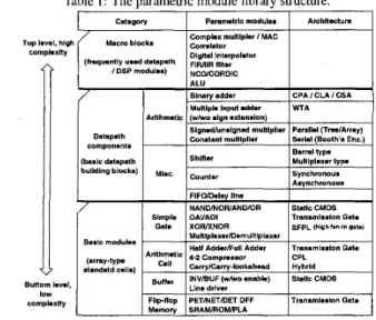
Table 1 : The parametric module library structure.
PETINETIDET DFF Transmlsdon Gate
SRAMIROMIPLA Dstapalh
components
(basis datapath bulldlng blocks)
3. PARAMETRIC MODULES AND HARDWARE RELATED DATA CLASSES
Table 1 lists the proposed C++ parametric datapath module library. The basic modules, which are just arrays of standard cellslprimitives, lie in the bottom level of the hierarchy. The datapath components, which are composed by basic modules and other datapath compo- nents, lie in the middle level of the hierarchy. The macro blocks that are frequently used in large datapath or DSP core design be- long to the top level of the hierarchy. All modules inherit the base module class, BuseModule, which encapsulates the netlisting func- tions (for the Verilog structural description/C++ function simula- tion code generation), parameter estimating functions(for area, la- tency, and power estimation), and several maintenance routines. Most of them are executed in a hierarchical manner, i.e., they have a similar behavior that recursively call the homonymous functions in their submodules.
Figure 2(a) depicts the work phases of a module. Each work phase corresponds to a set of member functions defined in Base- Module. In module registration and port defining phases, the sys- tem performs memory allocation, port mapping and object regis- tration routines. In structural information defining phase, the mod- ule allocates its submodules, internal nets, and specifies submod- ule connectivity according to U 0 port widths and parameters given in parameter setting phase (The U 0 port widths are implicitly de- fined in net data structure). Then, the submodules can be re-timed or sorted according to the data dependency. The functions in the submodule data-dependency analysis block are depicted in Figure 2(b). Basically, they perform a well-known levelization process that computes the "level" of each module, and sort the modules by their levels. An example that levelizes two modules and their
"0 loop
r"i,
are broken by synchronizers RaiseExam loops
In submodules
fail (recursive call)
I
iunctio;11
s t r i c r l-
11
e rI
I
-1
submodules simulation code description
Figure 2: (a) The generic life-cycle of a module, and (b) the sub- module data-dependency analysis block.
g TSubmodule @ i e +
#1 Submodule #1 : f = max {e,c} +1 Submodule #2 : d = e = max {a,b} +1
Figure 3: The levelization procedure.
output nets is shown in Figure 3. Because the data dependency is unknown, the process should be repeated until the level of each node stop changing. Therefore, the running time of the leveliza- tion process is a quadratic function of the module size, which is acceptable because this process is executed only once.
The hardware-related data classes are used to describe the data exchange or connection between modules. In Verilog gate-lwel representation, we declare wire variables to connect modules. This type of variable is not capable of storing values. (The storage el- ements are implicitly declared in primitivedUDP). However, to easily pass parameters/values between C++ modules, we declare variables that can store values in each modules. To support vari- ous data types and operations existing in HDL, we introduce sev- eral C++ classes with the following features:
Provide variable and constant fixed-point types with nearly unlimited precision (number of bits). Each type is automat- ically truncated or sign-extended if necessary.
Each type possesses basic functions/operators for arithmetic, compare, logical, assignment, and type converting opera- tions.
Support bit-level addressing and arbitrary data/wire con- catenations.
4. FUNCTIONS FOR SIMULATION, PARAMETER ESTIMATION, AND NETLISTING
In our C++ simulation methodology, the timing model is chosen to be cycle-based. Function simulation can be performed by repeat- edly changing the main module inputs, and calling the simulation
routine to evaluate the module outputs. The C++ code is gener- ated by the module according to either the structural information or user-specified functions. The default module simulation routine evaluates submodule outputs (invokes simulation routines of sub- modules) according to submodule data dependency analyzed in the submodule data-dependency analysis phase (Figure 2).
The C++ language shows a remarkable advantage over C or HDL because the designers can overload the simulation routine to verify the module functionality or to speed up functional sim- ulations. For example, the default simulation routine of the main module (e.g. tree multiplier) calls its submodule simulation rou- tines, namely, the simulations routines of the AND-plane / the Booth’s encoders, the Wallace tree adder, and the high-speed bi- nary adder. In addition, the behavior of each module can be mod- eled by a pure function followed by a delay element with variable number of cycles. Hence programmers can also design a simu- lation routine with a binary multiplication and time delays. The latter simulation routine is more abstract and irrelevant to the de- tail structure of the tree multiplier, and is suitable when only func- tional correctness is of concern. Module designers can compare the outputs of the two routines to uncover design flaws in the mod- ule structural information defining phase. Moreover, to speed up simulations, designers can overload the default simulation routine using the simple routine once the module has been verified. Fur- thermore, if the default simulation routine has been overloaded, we can just perform simulation without specifying the module struc- tural information (refer to Figure 2(a)). This does agree with the concept of high-level simulation.
Since parametric module can support many parameter config- urations, designers need a fast way to choose a proper configu- ration to implement. The parameter estimating functions encap- sulated in a module are designed to evaluate several characteris- tics/parameters (e.g. gate-count, area, delay or power consump- tion) for design-space explorations from a system perspective. By calling these functions after defining structural information, de- signers can acquire the knowledge about module characteristics, and try another parameter configuration if necessary. The default parameter estimating functions provided by the BnseModuZe class are briefly described below:
The gate-count estimating function returns the sum of sub- ” Y
module gate-count.
The area estimating function returns the sum of submodule area plus some area for routing.
The power estimating function estimates the data activity of each net declared in this module, and then calculates the dynamic power according to the data activity and the capac- itance (fan-in, fan-out) information stored in each net. The function returns the power dissipation of these nets, plus the power dissipation of submodules.
The propagation delay estimation is done using a static tim- ing analysis algorithm similar to the levelization process mentioned above.
The above parameter estimating functions are designed to quickly estimate the module characteristic and hence, are very simple. Mod- ule designers can overload the functions with more accurate ones.
The netlisting function dumps the Verilog description of the module. In this function, the system traverses all the submod- d e s , and dumps the nets and submodule connection recorded in the module data structure. Since C++ code should be compiled be- fore execution, a naming mechanism is required. Here we simply
assign an object name using an alphabetical prefix concatenated with the object serial number. The parametric module names, on the other hand, are assigned according to the parameter values.
5. MODULE DESIGN EXAMPLES
To design a parametric module, we just declare a new class that inherit the BaseModule, and overload the module organization function (define structural informations). This function allocates submoduleslinternal nets (Regs objects) and specifies the module connection using the internal nets or module ports. Moreover, the structured statements in C/C++ (for; while, repent, ifj facilitate the parametric description for allocation and connection of module in- stances.
When a module has been designed, users can allocate an mod- ule instance and execute its organization and data dependency an- alyzing functions. Next, the C++ code of the module can be gen- erated automatically such that users can perform simulations. For example, users can assign a nested for-loop to verify the module functionality for all input conditions. On the other hand, users can call the parameter estimating functions to roughly check the module characteristics. Once the input parameters and port widths are determined, users can execute the module netlisting function to generate the gate-level Verilog code. Figure 4 demonstrates two simple design examples. The C++ statements in module organi- zation functions and the corresponding Verilog netlist are listed together for comparison. Obviously, there is a strong analogy be- tween the two representations.
Array of full adders (basic module)
FAdds(this,CO,S,A,B,Cl); C ... 4-2 compressor p I new Rsgs(lhls.3.0); A I 4 0 l 8[40] D[4:0] Cl C[401
Figure 4: Modules constructed by basic modules. In the C++ statements, the left-shift operators
“<”
and “<=” are overloaded for wire concatenation. For the carry propagate adder shown in Figure 4, we concatenate the current module I/O ports CO, CZ with the net C, and pass them to the submodule(FAdds). Similarly, in a usual statement likes “a[3]=b[4]+1;”, the bucket op- erator “[1”
is overloaded for bit addressing operations. These op- erators utilize several features of C++ (Reference, Automatic type conversion, Copy constructor, etc.) for passing structural informa- tion and are transparent to module designers.In the next example shown in Figure 5 , we allocate a module instance of a tree-type parallel multiplier that is connected with
two 54-bit input ports. We call the organization and pipeline func- tions to generate a pipelined 54x54 tree multiplier. Then, we call the netlisting function to generate the Verilog structural descrip- tion and C++ function simulation code. The multiplier gate count reported by the system is 30273, which is approximately IOOK transistors. The Verilog description is then placed and routed. TSMC 0.6pm SPTM technology is selected and the layout size is 2802pm x 231 1pm. Consequently, an module layout is soon delivered. Since the designer does not need to manually design the gate-level code, the design gap between the C++ module design and layout design (place and route) is now bridged and a design can be completed smoothly and efficiently.
Tradlllonal (manually mwnle RTL code) 1
7
Doslgn lmmrrork proposed by 12.31 (b)Figure 5: Mapping designs onto silicon : (a) The layout of a 54x54-bit tree multiplier, and (b) its Verilog gate-level simulation result.
6. CONCLUSION
In this paper we demonstrate a parameU,ic datapath module library design based on the proposed C++ module design framework that encapsulates simulation, parameter estimation, and netlisting rou- tines into one C++ class. Under this framework, we can design hardware modules using existing ones and perform simulations with other algorithmslprograms written in C/C++. Once the sys- tem design is completed, efficient gate-level Verilog code can soon be delivered. This approach drives a hardware design directly from C++, and keeps a tight consistency between different lev- els of abstraction. A feature summary and comparison between different system design methodologies are listed in Table 2. The proposed design framework listed at the right-most column seems simpler and superior to the other methodologies in datapathlDSP design. We believe this design framework is a fast, robust, and
cost-effective solution to high-complexity datapath/DSP module design.
I 4
C++ compller
DBIlg“ llme long short
ReqUlred loola 10, c++ cawller c++ complier
functlon almulallon synlhesller C-la-RTL translator
and netllollng loglc symheslzer
Intormallon of a module. The behwlor desErlptlon
01 a module. I* apllonal.
class, template, macro
and preprocessor
lermlnologles
Fun~llons Dump C++NNerllog code
e”c.Ds“I.1ed I” slmulallon osmmter e s l l m l l o ”
C++ modules
I
slmulallonSlmulallon model euenldrlven
1
cyclabared cyclebasedSlmulallon speed SlOW last f a d
gale-level Verllog
Imclbn ?ilmulallon RTL VerllagNHDL C++ code lor
Design reufeablllly
7. REFERENCES
L. Geppert, “Design tools for analog and digital ICs,” IEEE
Spectrum, Apr. 1999, pp. 41-48.
J. Sanguinetti, “Bridging the design gap with Cynthesis,” Cy- nApps Company web page: http://www.cynapps.com/, 1999. Frontier Design Press, “C spans floating to fixed-point gap,” Fron-
tier Design Company web page: http://www.frontierd.com/, Jun. 1999.
H.M.A.M. Arts, J.T.J. van Eijndhoven, and L. Stok, “Flexi- ble block-multiplier generation”. International Conference on
Computer-Aided Design. Digest of Technical Papers. Santa
Clara, CA, Nov. 1991, pp. 106-109.
J. Hsu and 0. Bair, “A compiler for optimal adder design,”
Proceedings of the IEEE Custom Integrated Circuits Confer- ence, Boston, May 1992, pp. 25.6.1-25.6.4.
J. Nunni, “Portability Methods in Parametrized DSP Module Generators,” Proceedings of IEEE Workshop on VLSI Signal
Processing, New York, Oct. 1993, pp. 260-268.
J. Pal Singh, A. Kumar, and S . Kumar, “A multiplier gener- ator for Xilinx FPGAs,” Proceedings ofthe 9th International
Conference on VLSI Design, Bangalore, India, Jan. 1996, pp.
322-323.