Physical Analysis of a Biomimetic Microphone With
a Central-Supported (C-S) Circular Diaphragm for
Sound Source Localization
Chien-Chang Chen and Yu-Ting Cheng, Senior Member, IEEE
Abstract—This paper presents a physical analysis of the biomimetic microphone designed with a central-supported (C-S) diaphragm for the sound source localization. A clover-stem-like C-S design is proposed and achieving 47% improvement of net diaphragm displacement in comparison with the conventional C-S diaphragm design. The new design can effectively not only compensate undesired deformation of sensing diaphragm due to gravity and residual stresses but also make the diaphragm more flexible for better sound pressure sensitivity.
Index Terms—Biomimetic microphone, central floating joint, central-supported diaphragm, clover, hybrid, MEMS microphone, parasitoid fly, quality factor, sound source localization, squeeze film air damping effect.
I. INTRODUCTION
S
OUND source localization is a physiological ability of animals to process sensory information regarding the orientation and magnitude of sound pressure stimulation. The source localization is achieved via the differences of sound intensity and arrival time sensed by two ears which are geomet-rically close but far away from the sound sources. For a large mammal, two auditory organs are acoustically isolated by its head to have a large interaural distance (ID). For instance, the auditory system of an adult human with an ID of 20 cm can have an interaural time delay (ITD) of 600 and interaural intensity difference (IID) of about 16 dB between the ears with a 5 KHz tone sound pressure stimulus. Such minute ITD and IID are adequate for reliable time coding and processing in auditory nervous systems for sound source detection [1]. In contrast, two auditory organs of small animals are quite close to each other, so there would be a problem for the auditory system to experience insignificant interaural differences resulted by the tiny ID, about two orders of magnitude smaller than thatManuscript received April 21, 2011; revised October 03, 2011; accepted Oc-tober 16, 2011. Date of publication OcOc-tober 28, 2011; date of current version April 13, 2012. This work was supported in part by the NSC of R.O.C. under Grant NSC 100-2220-E-009-007-, and also in part by the Ministry of Education in Taiwan under the ATU Program. The associate editor coordinating the review of this paper and approving it for publication was Prof. Gerald Gerlach.
C. C. Chen is with Microsystems Integration Laboratory, Department of Electronics Engineering and Institute of Electronics, National Chiao Tung University, Hsinchu 300, Taiwan (e-mail: gettgod.ee92g@nctu.edu.tw; gettgod@gmail.com).
Y. T. Cheng is with Microsystems Integration Laboratory, Department of Electronics Engineering and Institute of Electronics, National Chiao Tung Uni-versity, Hsinchu 300, Taiwan (e-mail: ytcheng@mail.nctu.edu.tw; ytcheng@g2. nctu.edu.tw).
Color versions of one or more of the figures in this paper are available online at http://ieeexplore.ieee.org.
Digital Object Identifier 10.1109/JSEN.2011.2173931
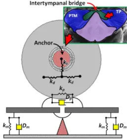
Fig. 1. Scheme of central-supported gimbal circular biomimetic diaphragm. The upper insertion shows the auditory organ of the parasitoid fly Ormia
ochracea whose entire auditory organ is only 1.2 mm. The intertympanal
bridge connecting two prosternal tympanal membranes (PTMs), i.e., the ipsi-lateral and the contraipsi-lateral prosternal tympanal membranes, via the tympanal pits (TP) in a manner of flexible coupled pivot can cause the two PTMs to deflect in opposite directions. The lower insertion shows the mechanical model of the central-supported gimbal circular biomimetic diaphragm.
of large animals. Therefore, the methodology of sound source localization in the tiny auditory system could lead the way to develop the next generation acoustic sensing and tracking microsystems like hearing aids, robots, and bionic military devices. In recent two decades, the acoustic sensing mechanism and auditory behavior of the parasitoid fly (Ormia ochracea) whose entire auditory organ is only 1.2 mm, as shown in Fig. 1, have been thoroughly investigated. Several studies demonstrated that the acoustic interaction between ipsilateral and contralateral prosternal tympanal membranes (PTMs) can effectively increase the interaural differences for locating sound sources by means of an intertympanal bridge structure as a mechanically coupled pivot [1]–[10]. The ipsilateral and contralateral membranes are defined as the membrane on the same side as and the one on the opposite side to the sound source, respectively.
The intertympanal bridge connecting the two PTMs via the tympanal pits (TP) functions like a flexibly coupled pivot that can cause the PTMs to deflect in opposite directions. In other words, under an insignificant IID stimulus, the two fly-ears con-strained by the intertympanal bridge will move in the opposite direction with roughly equal amplitudes. It indicates that an in-teraural phase difference (IPD) of 180 would be formed in all
frequency spectra [2]. The mechanical time delay (MTD) be-tween the ipsi- and contralateral ears can be equivalent to a half of the stimulation period due to the IPD of 180 . For instance, the MTD between the ipsi- and contralateral fly-ears will be equivalent to 100 under a 5 kHz tone sound pressure stim-ulus with the corresponding wavelength and period of 6.8 cm and 200 , respectively. Since the net displacement of the con-tralateral membrane would be a superposition of the displace-ments caused by the delayed sound pressure and the transfer of the ipsilateral deflection by mechanically coupling via the inter-tympanal bridge, the net displacement differences resulted by the two causes within the two PTMs could make the parasitoid fly easily detect the sound source.
As an incident sound wave with an angle relative to the lon-gitudinal axis of an auditory system is applied on the system, the ITD between the ipsi- and contralateral auditory organs should be expressed as [2]:
(1) where is the sound propagation speed with a value of 344 m/s at room temperature. For instance, the ITD is about 7 to ei-ther the parasitoid fly or any specific animal with the same audi-tory system size as the fly but without the mechanically coupled pivot, when an incident sound wave hits the fly with . With a 5 KHz tone sound pressure stimulus, the tiny ITDs of the fly or the specific animal can only result in the same ampli-tudes of the PTMs as well as the same oscillating direction with slight phase difference. Fortunately, by considering the afore-mentioned mechanism of the MTD, the time delay caused by the mechanically coupled pivot of the fly will dominate with a larger value which is about 14 times of the ITD ( /7 ) and the PTMs can move in the opposite directions simul-taneously. Thus, the employment of the mechanically coupled pivot indeed can enhance the ability of the tiny auditory system for sound source localization. In a nutshell, the concept of the tiny auditory system with such a mechanically coupled pivot can provide an important design feature for Micro Electro-Me-chanical Systems (MEMS) microphones for hearing aids appli-cations in terms of sound source localization [11]–[15].
Previously, an acoustical structure with a central-supported (C-S) sensing diaphragm in microscale as shown in Fig. 1 was proposed for sound source localization by imitating the aforementioned auditory mechanically coupled principle of the parasitoid fly [11], [12], [15]. The proposed design had drawn lots of attention due to the characteristics of simple fabrication process, easy sensing circuit implementation, and excellent directional identification as well as spatial resolution in com-parison with the other biomimetic designs [13], [14]. However, lacking of physical intuition and a complete theoretical model in terms of material and dimensional characteristics has caused the difficulty in design optimization of the C-S diaphragm for device designers. Further investigation is required to reveal the related mechanical dynamics with significant physical explanations for sound source localization. In the paper, we construct a corresponding physical response model with air damping effects from which the auditory dynamical behaviors of the C-S diaphragm can be fully elucidated.
II. CONSTITUTIVEFORMULATION
By considering the conventional C-S design as shown in Fig. 1 with the detail schematic diaphragm and mechanical configuration, the corresponding equation of motion for the ipsi- and contralateral displacements of the diaphragm can be derived as follows [2], [15]:
(2) where and , and , and , , and are the stiffness coefficients of the membrane and the coupled pivot, the displacements of ipsi- and contralateral mem-branes, the damping coefficients of the membrane and the cou-pled pivot, the mass of entire diaphragm, and the driving force loaded onto the ipsi- and contralateral membranes, respectively. According to the mechanical model as shown in Fig. 1, the pa-rameter is physically equivalent to the linear combination of the spring constant of deflection ( ) and two times that of twist ( ), i.e., . The parameter is equivalent to the spring constants of deflection . In general, the corresponding dis-placements of the ipsi- and contralateral membranes in a steady state can be expressed by a linear combination of the displace-ments of translational and rocking modes in time domain [2]:
(3) where and are the amplitudes of translational and rocking modes, respectively. Meanwhile, by physically considering the angle of twist and deflection of the diaphragm caused by the time-variant sound pressure, these amplitudes can be expressed in terms of operating frequency and material characteristics:
(4-1)
and
(4-2) where
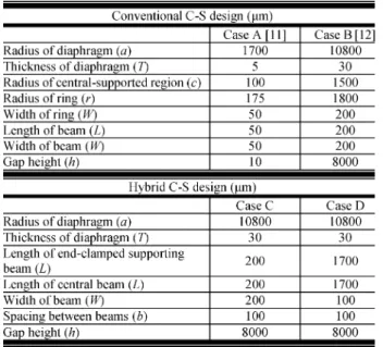
TABLE I
DIMENSIONALPARAMETERS OF THE CONVENTIONAL ANDHYBRIDC-S DESIGNS
The parameters , , , , , and , and are outer ra-dius of the diaphragm, inner rara-dius of the diaphragm, the ITD derived in (1), width of the beam, thickness of the diaphragm, shearing modulus and Young’s modulus of the structural mate-rial, and magnitude of time-variant sound pressure applied on the membranes, respectively. The phase coefficients mentioned in (3) are described as follows:
(6) In (4) and (5), the and , and and are the natural reso-nant frequencies and the damping ratios of the translational and rocking modes, respectively [2]. Table I shows the dimensional parameters of the C-S diaphragm microphones. According to (5), the corresponding theoretical calculations of the resonant frequencies of the rocking and translational modes are about 621 Hz and 1186 Hz, respectively, which are very close to the results of finite element analysis (FEA) simulation presented by the previous study in Case A listed in Table I [11].
Fig. 2 shows the schematic diagrams regarding the geomet-rical structures of the structurally coupled C-S designs. Obvi-ously, the conventional C-S design can be mechanically divided into two regions, i.e., the central-supported region and the di-aphragm, that are connected to each other using a asymmetric beam structure as shown in Fig. 1. The design of the asymmetric beam structure with a large aspect ratio of the outer radius to the thickness ( to 1) usually accompanies with an undesired diaphragm deflection caused by the gravitational force. For in-stance, the torque contributed by the gravitational force which is applied on the outer beams will lead to drastic deflections on the edges of the ipsilateral and contralateral diaphragms and should be considered in the design. Thus, the induced deflection, ,
Fig. 2. Schematic diagrams regarding the geometrical structures for (a) the conventional and (b) the hybrid C-S designs.
caused by the gravitational force is calculated as the superposi-tion of the deflecsuperposi-tions of diaphragm and that of the asymmetric beams:
(7) where and are the gravitational acceleration constant and length of the beam, respectively. By employing the undesired gravitational effect into the equation of diaphragm motion, the net ipsi- and contralateral displacements can be expressed as and , respectively. For the ca-pacitive biomimetic microphones for sound source localization, these net displacements are the indicators to identify the sensi-tivity of the device [16]. The designers can, therefore, determine the minimum gap height between the diaphragm and the sub-strate as well as the maximum capacitances by considering the net displacements caused by the summation of the applied sound pressures and the gravitational effect in design stage using the derived equation of diaphragm motion.
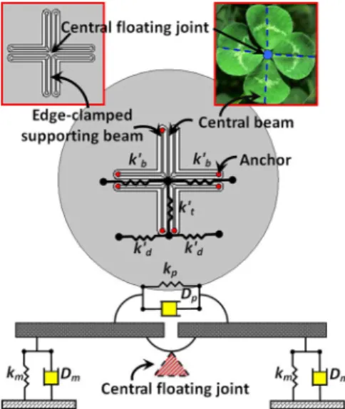
In the prior analysis, (4) and (5) disclose a new finding in terms of biomimetic microphone structure: net displacements of a C-S diaphragm will increase with the decrease of the radius of central-supported region. On the other hand, from (7), the undesired deformation could be also aggravated due to the gravitational force. In order to enhance the net displacements and conquer the undesired deformation simultaneously, a new central floating gimbal structure as shown in Fig. 3 is demon-strated for the next generation of biomimetic C-S microphone. By hybridizing the mechanical characteristics of the sensing mechanism of the parasitoid fly and the clover-stem-like gimbal structure, the conventional C-S structure is further modified using eight end-clamped supporting beams connected to a central floating joint. Fourfold-rotation axial symmetry of the clover-stem-like gimbal structure is adopted to replace the conventional asymmetric beam structure. The entire mass of the diaphragm is supported by four central beams whose ends are connected to form the central floating joint which performs like a freely suspended support. Thus, while the diaphragm is released from the substrate underneath itself, the effects of gravitational force or residual stress on the displacement of the diaphragm can be effectively compensated by the concentrated moments which are resulted by the reaction forces applied to the joint [17], [18]. In comparison with the conventional design (Case B), the initial deformation shown in Table II indicates
Fig. 3. Scheme of the hybrid biomimetic microphone with central floating gimbal design achieving by hybridized by the acoustic sensing mechanism of the parasitoid fly and the flexible clover-stem-like gimbal structure. The lower insertion shows a new mechanical model with the central floating joint.
that the hybrid C-S design (Case C) could have better resistance to the undesired deformation which is also validated by both theoretical calculation and FEM analysis using ConventorWare simulator [19] with the dimensional parameters listed in Table I. Meanwhile, the net displacement of the hybrid C-S design can not only have the typically acoustic responses resulted by the twist of the beams perpendicular to the direction of incident sound pressure and the deflection of the diaphragm along the direction of wave propagation but also have additional responses caused by the deflection of the central beams along the direction of propagation which can greatly enlarge the displacement of the diaphragm.
Thus, the parameters and of the hybrid C-S design should be structurally modified through the linear combination of the spring constants of the deflection of the membrane, that of the central beam, and that of the twist of the central beam, i.e., , and , respectively. Equations (4) and (5) can be likewise modified as follows:
(8) where
TABLE II
COMPARISONBETWEENMODELPREDICTION ANDSIMULATION OF THEINITIALDEFORMATION
TABLE III
THEORETICALCOMPARISON OF THESTIFFNESSCOEFFICIENTS OF THEROCKING AND THETRANSLATIONALMODES FOR THECONVENTIONAL AND THE
HYBRIDC-S DESIGN, RESPECTIVELY
(9) Meanwhile, the initial deflection caused by the gravitational force should be also mechanically and structurally modified as follows:
(10) Table III lists a theoretical comparison of the stiffness coef-ficients of the rocking and translational modes in the conven-tional and the hybrid C-S designs, respectively. It is obvious that both stiffness coefficients of the rocking ( ) and translational ( ) modes of the hybrid C-S design are smaller than that of the conventional design as well as the natural resonant frequencies in both modes. According to the derived (4) and the two-degree-of-freedom (2-DOF) model [20], the smaller the natural resonant frequency is, the larger the displacement of the diaphragm will be. The sensitivity and directivity of the biomimetic microphone with the hybrid C-S design will be also enhanced. It is noted that the rocking-mode frequency of the hy-brid C-S design has about a 50% reduction, so the amplitude of rocking mode can be effectively increased using the hybrid C-S design.
Additionally, the performances of the biomimetic micro-phones can be also strictly compared using two mechanical indicators, the mechanical interaural intensity difference (mIID) and the mechanical interaural phase difference (mIPD) [20], which can be expressed as follows:
(11) and
For the case of sound source localization via the biomimetic mi-crophone, the ipsi- and contralateral membranes moving in the opposite directions with equal amplitudes must have the mIID and mIPD with the values of near 0 dB and 180 , respectively. According to the theoretical calculations, the values of the mIID and mIPD for both the conventional and the hybrid C-S designs are 16.1 dB and 99.1 , and 16.6 dB and 98.5 , respectively. In a nutshell, as compared with the mIID and mIPD of the con-ventional C-S design, the performance of the hybrid C-S design can be enhanced in terms of the displacement increase of the di-aphragm without any mechanical performance degradation by dramatically decreasing the rocking-mode stiffness.
III. DERIVATION OF QUALITY FACTOR AND
DAMPINGCOEFFICIENTS
The “quality factor” of an oscillating system can be ap-proximately and typically described as follows [21], [22]:
(13) where is the damping ratio of either rocking or translational mode. According to the extraction of the damping coefficients from the previous experiments [12], the value of is roughly larger than unity. Thus, in the case, the factor is a poor value or even an imaginary number. At the moment, the microphone performs in either a critical-damping or an over-damping mode. The oversimplified (11), however, does not completely re-veal the detail relationship between the acoustic dynamics of the microphone and the air damping effect [23]–[25], thereby incorporating the squeeze film air damping model and the en-ergy transfer model for revealing the interaction between mi-crophone diaphragm and air. Two obvious motion mechanisms occur while the diaphragm is loaded by sound pressure: normal motion and rotation of the diaphragm. By means of the energy transfer model, the quality factors can be obtained in terms of the quality factor of the normal motion, , and that of the ro-tation, , and be expressed as follows [23]–[25]:
(14) where
(15) and
(16) The parameters , , , , , and are mass den-sity of the diaphragm, gap height, universal molar gas constant, molar mass of air, ambient temperature, the moment of inertia of supporting beam, and the resonant frequency of either rocking or translational mode, respectively. The exact definitions of the damping ratio and resonant frequency are referred to the (5). Equation (16) obviously reveals that the damping ratios as well as the damping coefficients are significant parameters for de-riving the quality factors. Thus, a complete discussion of the
TABLE IV
THEORETICALCALCULATIONS OF THEQUALITYFACTORS FOR THE
CONVENTIONAL AND THEHYBRIDC-S DESIGN, RESPECTIVELY
damping coefficients can helpfully clarify the interaction be-tween the viscous air and the diaphragm. Table IV lists the the-oretical calculation of the quality factors of both rocking and translational modes in the conventional and the hybrid C-S de-signs, respectively.
The viscous damping indeed affects the dynamic responses of the acoustic sensors as well as the quality factor. Although sev-eral researches regarding the effects of squeeze film air damping have been investigated and provided with detail physical and mathematical models [23]–[25], there is still no exact solution to well model the C-S structures of the acoustic sensors. There-fore, for the demand of the solution at this stage, the damping effect of the C-S structure will be discussed and established as follows. For the circular diaphragm of the C-S design, the non-linear Reynolds equation can be introduced for describing the air damping effect in a cylindrical coordinate [24], [25]:
(17) with the specified boundary conditions:
(18) where , , and are the damping pressure, the air viscosity, and the tilting angle, respectively. By integrating (17) with the boundary conditions, the damping pressure can be expressed:
(19) The torque of the damping force can be then calculated as fol-lows:
(20) By realizing the Newton’s mechanics, the damping coefficient of the membrane is the proportional constant of (20) and can be eventually derived as:
(21) Similarly, by considering the mathematical approaches of the nonlinear Reynolds equation with specific boundary conditions in the normal motion, damping force on the diaphragm is then calculated as follows:
Fig. 4. A side view of the diaphragm.
The damping coefficient of the coupled pivot is the proportional constant of the damping force and can be derived as:
(23) Generally, the sensing diaphragm is embedded in a cavity as shown in Fig. 4 for preventing the incident sound pressure from leaking to the back [12], in which the trapped air is difficult to escape to infinite space [23], [26]. The air damping effect on the edge of the diaphragm from sidewalls of the cavity should be also specified. By employing principles of the mass conser-vation [24] and the Poiseuille equation, the volume flow of air per second escaped from the edgewise ( ) should be equal to that squeezed by the plate ( ):
(24) where , and and are the area between the cavity wall and the diaphragm, the pressure difference in -direction, di-aphragm thickness respectively. Thus, by differentiating the respected to twice, we can approximately obtain that:
(25) In the situation with tiny displacements, we can assume that the damping pressures under the diaphragm and at the edge-wise is smoothly continuous, that is, would be approximately equal to . Therefore, by combining the nonlinear Reynolds equations used to described the damping pressures under the diaphragm and at the edgewise, the damping equation for the studied case can be further derived as follows:
(26) Thus, the gap height mentioned in (21) and (23) should be mod-ified as follows, while the diaphragm is embedded in the cavity: (27) In the studied case, the and are 8000 and 200 , respectively, so the effective gap height is about 193 , which is more than an order of magnitude smaller than the value. The damping coefficients as well as the damping ratios for
Fig. 5. The comparison of the ipsilateral displacements of the conventional biomimetic microphone between the theoretical calculations with varying damping rations and the measured data [12]. The damping ratios closed to unity indicates that the biomimetic microphone is critically damped so that the responses will directly follow the transient inputs.
both rocking and translational modes can then be well derived by combing (5), (21), and (23).
Fig. 5 shows the comparison of the ipsilateral displacements of the conventional C-S microphone between the theoretical cal-culations with varying damping ratios and the measured data [12]. The measured data with the damping ratios close to unity indicates that the biomimetic microphone is critically damped. In a nutshell, the critical damping motion of the microphone will make itself act with the sensing responses which directly follow the transient inputs. It is noted that the strictly experi-mental validations are definitely required in the further research studies, even though the quality factors and the damping coef-ficients have been derived theoretically and used for well de-scribing the responses of the conventional C-S design.
IV. MODELVALIDATION ANDDISCUSSIONS
For a fair comparison of the functionality between the con-ventional and the hybrid C-S designs, it is convenient to make artificially, that would lead the length, thickness, and width of all beams used in the hybrid C-S design to be 8.5, 1, and 0.5 times of that in the conventional design, respectively. The new structure is denoted as the Case D listed in Table I. The comparison between the theoretical calculations and the Con-ventorWare simulation [17] of the and the for these two designs are revealed in Table II, respectively. Good data agreement also reveals the accuracy of the physical model for the prediction of the undesired deflection. According to the the-oretical calculations, the hybrid C-S design can enhance the am-plitude of the rocking mode due to the reduction of the associ-ated stiffness coefficient. Fig. 6 shows the mechanical schemes with the corresponding simulation results in the conventional and the hybrid C-S designs under external influences, respec-tively. Obviously, the conventional Case B-typed C-S design only has two outer beams to support the entire mass of the di-aphragm as shown in Fig. 6(a), whereas the Case C-typed hy-brid design using the clover-stem-like gimbal structure has four central beams to execute the same function. Meanwhile, the Case D-typed hybrid C-S design also reveals larger displace-ments than that of the Case B-typed conventional design shown
Fig. 6. Mechanical schemes and associated simulation results of deformation of the conventional and hybrid C-S designs due to the influences of (a) gravita-tional force and (b) sound source pressure, respectively. The convengravita-tional C-S design of the Case B only has two outer beams to support the entire mass of the diaphragm as shown in (a), whereas the hybrid one of the Case C has four cen-tral beams to execute the same function. Meanwhile, the hybrid C-S design of the Case D also reveals larger displacements than that of the conventional one of the Case B as shown in (b), in which they have the same initial deformations.
in Fig. 6(b). The structure of the central floating joint accom-panied with the central beams indeed provides better coupled mechanisms for improving sound source sensitivity and the re-sistance to undesired deformation. Therefore, the employment of the clover-stem-like gimbal structure can not only conquer the undesired gravitational force as aforementioned due to the torques of the central beams resulted by the reaction forces in the opposite directions, but also improve the displacement of the diaphragm by means of its mechanically coupled structure.
Fig. 7 shows the comparison results of the measured data of the previous study [12] with the associated theoretical calcula-tions in both of the Case B-typed conventional design, and the Case D-typed hybrid one with specified dimensional parame-ters listed in Table I. The stimulation of 60 dB, 200 Hz sinu-soidal sound wave is employed as the loading sound source for the comparison. Two sets of the damping ratios, i.e.,
and , and and , respectively, are estimated and adopted in theoretical calculations of the conven-tional and the hybrid C-S designs, respectively. Excellent data
Fig. 7. Comparison of the (a) ipsilateral, (b) contralateral, and (c) net displace-ments between model analyses and experimental measurement demonstrated by Ono et al. [12] with applying 60 dB and 200 Hz sinusoid sound waves, respectively.
match between the theoretical calculations and the measurement results of the Case B-typed conventional C-S design shows the accuracy of the presented physical model and further indicates that the hybrid C-S design can have about 47% improvement of the net diaphragm displacement. Therefore, higher sensitivity as well as directivity improvement can be realized by the pro-posed hybrid design in comparison with the conventional one [11], [12].
The derived model physically and mechanically reveals a finding with significant physical meanings: Based on (3), the displacement of the either ipsi- or contralateral membranes is dominated by the amplitude of the translational mode. Since the superposition of the rocking-mode motion with the amplitude of the translational mode is the key factor in the design of sound source localization microphone, the performance optimization should focus on the design to make the resonant frequencies
of the two modes close to each other for enhancing the total dynamic response. In fact, according to the recent studies from Yu’s group [20], [26], [27], the fly-ear indeed needs to use a combination of the rocking and the translational modes to achieve the high performance of sound source localization [26]. As a result, the finding is definitely a solid evidence of the result inferred from the presented acoustic model.
V. CONCLUSION
A biomimetic microphone with the conventional C-S de-sign for sound source localization has been well analyzed. Meanwhile, we further propose a new hybrid biomimetic microphone accompanied with a clover-stem-like gimbal structure. By means of the dynamic analysis and the com-parison of the microphones with the conventional and hybrid designs, two significant important features are revealed: (1) the clover-stem-like gimbal C-S structure with a fourfold rotation axial symmetry can compensate the deformation due to gravity and residual stresses for exact sound source localization, and (2) the central floating joint makes the sensing diaphragm of the microphone more flexible for better sound pressure sensitivity. Additionally, the quality factors and air damping effect are also discussed theoretically. In order to further realize and verify the validation of the derived models, strictly experiments and investigations are required in the future.
ACKNOWLEDGMENT
The authors would like to thank Nano Facility Center of Na-tional Chiao Tung University and NaNa-tional Chip Implementa-tion Center for the support of the fabricaImplementa-tion and measurement instruments and the National Center for High-Performance Computing (NCHC) for the support of CoventorWare simulator.
REFERENCES
[1] D. Robert, R. N. Miles, and R. R. Hoy, “Directional hearing by me-chanical coupling in the parasitoid fly Ormia Ochracea,” J. Compar.
Physiol. A, vol. 179, pp. 29–44, Jul. 1996.
[2] R. N. Miles, D. Robert, and R. R. Hoy, “Mechanically coupled ears for directional hearing in the parasitoid fly Ormia Ochracea,” J. Acoust.
Soc. Amer., vol. 98, pp. 3059–3070, Jun. 1995.
[3] D. Robert, J. Amoroso, and R. R. Hoy, “The evolutionary convergence of hearing in a parasitoid fly and its cricket host,” Science, vol. 258, pp. 1135–1137, Nov. 1992.
[4] D. Robert, R. N. Miles, and R. R. Hoy, “Tympanal mechanics in the par-asitoid fly Ormia ochracea: Intertympanal coupling during mechanical vibration,” J. Compar. Physiol. A, vol. 183, pp. 443–452, Jun. 1998. [5] D. Robert, R. N. Miles, and R. R. Hoy, “Tympanal hearing in the
sar-cophagid parasitoid fly emblemasoma SP.: The biomechanics of direc-tional hearing,” J. Exp. Biol., vol. 202, pp. 1865–1876, Jun. 1999. [6] D. Robert and M. C. Göpfert, “Acoustic sensitivity of fly antennae,” J.
Insect Physiol., vol. 48, pp. 189–196, Feb. 2002.
[7] G. U. C. Lehmann and K.-G. Heller, “Bushcricket song structure and predation by the acoustically orienting parasitoid fly Therobia leonidei (Diptera: Tachinidae: Ormiini),” Behav. Ecol. Sociobiol., vol. 43, pp. 239–245, Mar. 1998.
[8] U. Köhler and R. Lakes-Harlan, “Auditory behaviour of a parasitoid fly (Emblemasoma auditrix, Sarcophagidae, Diptera),” J. Compar.
Physiol. A, vol. 187, pp. 581–587, Sep. 2001.
[9] A. C. Mason, M. L. Oshinsky, and R. R. Hoy, “Hyperacute direc-tional hearing in a microscale auditory system,” Nature, vol. 410, pp. 686–690, Apr. 2001.
[10] J. Sueur, E. J. Tuck, and D. Robert, “Sound radiation around a flying fly,” J. Acoust. Soc. Amer., vol. 118, pp. 530–538, Jul. 2005. [11] N. Ono, A. Saito, and S. Ando, “Design and experiments of
bio-mimicry sound source localization sensor with gimbal-sup-ported circular diaphragm,” in Proc. 12th Int. Conf. Solid-State
Sensors, Actuators Microsyst., 2003, pp. 935–938.
[12] N. Ono, A. Saito, and S. Ando, “Bio-mimicry sound source localization with gimbal diaphragm,” Trans. IEE Jpn., vol. 123-E, pp. 92–97, 2003. [13] L. Tan, R. N. Miles, M. G. Weinstein, R. A. Miller, Q. Su, W. Cui, and J. Gao, “Response of a biologically inspired MEMS differential microphone diaphragm,” in Proc. SPIE, 2002, vol. 4743, pp. 91–98. [14] W. Cui, B. Bicen, N. Hall, S. A. Jones, F. L. Degertekin, and R. N.
Miles, “Optical sensing in a directional MEMS microphone inspired by the ears of the parasitoid fly, Ormia Ochracea,” in Proc. 19th IEEE
Int. Conf. Micro Electro Mech. Syst., 2006, pp. 614–617.
[15] H. Liu, X. Zhang, and M. Yu, “Understanding fly-ear inspired direc-tional microphones,” in Proc. SPIE, 2009, pp. 2M1–2M11.
[16] S. Chowdhury, M. Ahmadi, and W. C. Miller, “Nonlinear effects in MEMS capacitive microphone design,” in Proc. Int. Conf. MEMS,
NANO Smart Systems, 2003, pp. 297–302.
[17] J. Reinke, A. Jajoo, L. Wang, G. Fedder, and T. Mukherjee, “CMOS-MEMS variable capacitors with low parasitic capaci-tance for frequency-reconfigurable RF circuits,” in Proc. IEEE Radio
Freq. Integr. Circuits Symp., 2009, pp. 509–512.
[18] Y. Zhang, Q. Ren, and Y.-P. Zhao, “Modelling analysis of surface stress on a rectangular cantilever beam,” J. Phys. D: Appl. Phys., vol. 37, pp. 2140–2145, 2004.
[19] CoventorWare 2008, , 2008 [Online]. Available: http://www.coventor. com/
[20] H. Liu, L. Currano, D. Gee, B. Yang, and M. Yu, “Fly-ear inspired acoustic sensors for gunshot localization,” in Proc. SPIE, 2009, pp. 73210A-1–73210A-8.
[21] M. Thornton, Classical Dynamics of Particles and Systems, 4th ed. Orlando, FL: Harcourt, ch. 3, pp. 116–131.
[22] L. D. Landau and E. M. Lifshitz, Mechanics, 3rd ed. London, U.K.: Butterworth-Heinemann, vol. 1, ch. 5.
[23] Z. Hao, R. Clark, J. Hammer, M. Whitley, and B. Wingfield, “Mod-eling air-damping effect in a bulk micromachined 2D tilt mirror,” Sens.
Actuators A: Phys., vol. 102, pp. 42–48, 2002.
[24] M. Bao and H. Yang, “Squeeze film air damping in MEMS,” Sens.
Actuators A: Physical, vol. 136, pp. 3–27, 2007.
[25] M. Bao, H. Yang, H. Yin, and Y. Sun, “Energy transfer model for squeeze-film air damping in low vacuum,” J. Micromech. Microeng., vol. 12, pp. 341–346, 2002.
[26] H. J. Liu, M. Yu, and X. M. Zhang, “Biomimetic optical directional microphone with structurally coupled diaphragms,” Appl. Phys. Lett., vol. 93, pp. 243902-1–243902-3, 2008.
[27] L. J. Currano, H. Liu, D. Gee, B. Yang, and M. Yu, “Microscale im-plementation of a bio-inspired acoustic localization device,” in Proc.
SPIE, 2009, pp. 73210B-1–73210B-8.
Chien-Chang Chen was born in Hualien, Taiwan.
He received the B.S. degree in physics from the Na-tional Central University, Jhongli, Taiwan, in 2003, and the M.S. and Ph.D. degrees from the Department of Electronics Engineering, Institute of Electronics, National Chiao Tung University, Hsinchu, Taiwan, in 2006 and 2011, respectively. His Ph.D. dissertation focused on the physical analyses of N/MEMS com-ponent structures for optimal micro- and nanosystem design.
He was an analog IC artist and contributed on high-speed level shifter and voltage controlled oscillator in QuadLink, Taiwan. He then became a Postdoctoral Researcher in Surface and NanoScience Lab, Insti-tute of Physics, Academia Sinica, Taipei, Taiwan, and studying the physics on cellular surface, AFM Cantilever with specified functionalities immersed in the liquid, and theory of electric signal propagation. So far, he is a Principal Engi-neer with Taiwan Semiconductor Manufacturing Company, Ltd. (TSMC) in the development of high speed, high density, and low noise memory for the next generation.
Dr. Chen is a member of the America Nano Society and the Phi Tau Phi Scholastic Honor Society.
Yu-Ting Cheng (SM’07) was born in Taiwan,
China. He received the B.S. and M.S. degrees in materials science and engineering from National Tsing Hua University, Hsinchu, Taiwan, in 1991 and 1993, respectively; the M.S. degree in materials science and engineering from Carnegie Mellon University, Pittsburgh, PA, in 1996; and the Ph.D. degree in electrical engineering from the Univer-sity of Michigan, Ann Arbor, in 2000. His Ph.D. thesis focused on the development of novel vacuum packaging technique for microelectromechanical systems (MEMS) applications.
He has been in Army service in Taiwan for two years. After finishing his Ph.D. study in 2000, he became a research staff member with IBM
Thomas J. Watson Research Center, Yorktown Heights, where he was involved in several system-on-a-package (SoP) projects. In 2002, he joined the Depart-ment of Electronics Engineering, National Chiao Tung University, Hsinchu, Taiwan, as an Assistant Professor and has been a Professor since 2009. His research interests include the fundamental study of materials for microsystem integration and nano/MEMS applications, SoP, and the design and fabrication of microsensors and microactuators.
Dr. Cheng was a co-recipient of the 2006 Best Paper Award presented at the 13th IEEE International Conference on Electronics, Circuits and Systems. He has served as a TPC member in IEEE International Conf. of NEMS since 2011 and APCOT 2012. He is a member of IOP, and Phi Tau Phi.

![Fig. 5. The comparison of the ipsilateral displacements of the conventional biomimetic microphone between the theoretical calculations with varying damping rations and the measured data [12]](https://thumb-ap.123doks.com/thumbv2/9libinfo/7757633.149189/6.891.469.811.95.308/comparison-ipsilateral-displacements-conventional-biomimetic-microphone-theoretical-calculations.webp)
![Fig. 7 shows the comparison results of the measured data of the previous study [12] with the associated theoretical calcula-tions in both of the Case B-typed conventional design, and the Case D-typed hybrid one with specified dimensional parame-ters list](https://thumb-ap.123doks.com/thumbv2/9libinfo/7757633.149189/7.891.67.429.96.645/comparison-measured-previous-associated-theoretical-conventional-specified-dimensional.webp)
