IEEE PHOTONICS TECHNOLOGY LETTERS, VOL. 21, NO. 2, JANUARY 15, 2009 103
Compensation for I/Q Imbalances and Bias Deviation
of the Mach–Zehnder Modulators in Direct-Detected
Optical OFDM Systems
Wei-Ren Peng, Bo Zhang, Xiaoxia Wu, Kai-Ming Feng, Alan E. Willner, Fellow, IEEE, and Sien Chi
Abstract—We demonstrate an equalization technique to
si-multaneously compensate for the fiber chromatic dispersion and the distortions induced by the in-phase/quadrature-phase (I/Q) imbalances and bias deviation in the Mach–Zehnder modulators (MZMs). With this technique, the requirement for the monitoring circuits at the transmitter could be relaxed or even eliminated, and thus simplifies the system design and reduces the system cost. The system exhibits a good performance with our proposal over a broad range of imbalances and bias deviation in the MZM. With deliberately introducing I/Q imbalances and bias deviation, we have observed a 2- and 4-dB optical signal-to-noise ratio improvement, for the back-to-back and 800 km of uncompensated standard single-mode fiber transmission, respectively, with our proposed scheme.
Index Terms—Optical fiber communication, optical modulation,
orthogonal frequency-division multiplexing (OFDM).
I. INTRODUCTION
O
PTICAL orthogonal frequency-division multiplexing (OFDM) is a promising modulation format for long-haul transmission due to its robustness to fiber chromatic dispersion (CD) and polarization-mode dispersion [1], [2]. The recently proposed direct-detected interleaved OFDM (OFDM-B in [3]) is one of the promising formats due to its better nonlinear tolerance compared with the gapped OFDM (OFDM-A in [3]), and better sensitivity and CD tolerance compared with the previous power-modulated OFDM [3].Similar to other optical systems, the OFDM performance crit-ically depends on the proper operation of the Mach–Zehnder modulator (MZM) [4]. The in-phase/quadrature-phase (I/Q) im-balances, which include 1) amplitude imbalance, 2) phase de-viation, and 3) time misalignment between the I/Q arms, and the bias deviation will degrade the system performance. Thus, a precise control and monitoring circuit for the MZM is required.
Manuscript received July 26, 2008; revised September 29, 2008. First pub-lished November 18, 2008; current version pubpub-lished January 14, 2009.
W.-R. Peng and S. Chi are with Department of Photonics and Institute of Electro-Optical Engineering, National Chiao Tung University, Hinchu 30056, Taiwan 300, R.O.C. (e-mail: pwr.eo92g@nctu.edu.tw; schi@mail.nctu.edu.tw). B. Zhang, X. Wu, and A. E. Willner are with Department of Electrical En-gineering, University of Southern California, Los Angeles, CA 90089 USA (e-mail: boz@usc.edu; xiaoxia@usc.edu; willner@usc.edu).
K.-M. Feng is with Institute of Communications Engineering, National Tsing Hua University, HsinChu, Taiwan 300, R.O.C. (e-mail: kmfeng@ee.nthu.edu. tw).
Color versions of one or more of the figures in this letter are available online at http://ieeexplore.ieee.org
Digital Object Identifier 10.1109/LPT.2008.2008819
However, it is possible to relax the requirements for the moni-toring and control circuit if these imbalance impacts can be com-pensated by the receiver-side digital signal processing (DSP).
Many receiver-side I/Q imbalance equalization schemes exist in wireless communication [5]. Unfortunately, these techniques tend to be difficult to use on direct-detection optical OFDM due to the square-law nature of the photodiode. Therefore, a laud-able goal for direct-detection optical OFDM would be to com-pensate for both the I/Q imbalances and linear channel impair-ments.
In this letter, we experimentally demonstrate a receiver-side compensation technique for a direct-detected interleaved OFDM system [3]. The received signal is equalized by a 2 2 matrix which can simultaneously mitigate the interferences resulted from I/Q imbalances and compensate the fiber CD. We test the performance of an 8 quadrature amplitude modulation (QAM), 10-Gb/s signal by deliberately introducing various imbalances and bias deviation in the MZM. The results indicate that the proposed method provides robust performance over a wide range of I/Q imbalances and bias deviation. After 800-km transmission of uncompensated standard single-mode fiber (SSMF), the proposed method can jointly compensate the added I/Q imbalances and fiber CD, and outperforms the con-ventional one-tap equalizer by 4 dB in optical signal-to-noise ratio (OSNR) measurements.
II. EQUALIZATIONTECHNIQUE
The effect of I/Q imbalance and the concept of compensation scheme are illustrated in Fig. 1. Shown in Fig. 1(a) is a typical optical I/Q modulator with various imbalances and bias devia-tion. The I/Q imbalances include 1) amplitude imbalance , de-fined as the amplitude ratio of the electrical inputs between I and Q arms; 2) phase deviation , an extra phase apart from the reg-ular between I and Q arms; and 3) time misalignment , a relative time delay between the two electrical inputs to I and Q arms. In addition, the bias deviation means any voltage departure from the optimum bias point (i.e., the null point).
The optical spectra of the ideal signal and the signal dis-torted by I/Q imbalances and bias deviation are shown in Fig. 1(b). From the optical spectrum of the ideal signal, the radio-frequency (RF) tone with an amplitude of is inserted on an odd-numbered subcarrier at the left edge of the signal band; while the data symbols for the positive and negative
subcarriers denoted as and are modulated on only
the even-numbered subcarriers to the right of the RF tone with
the frequency index of , where is the
number of the data subcarriers. The signal will suffer from the “mirrored interference” when there exists any I/Q imbalances
104 IEEE PHOTONICS TECHNOLOGY LETTERS, VOL. 21, NO. 2, JANUARY 15, 2009
Fig. 1. (a) Various I/Q imbalances and bias deviation. (b) Optical spectra with I/Q imbalances and bias deviation. M. I.: mirrored interference.
in the system [5]. With the I/Q imbalances, the interfered data symbols for positive subcarrier have now been polluted by its negative counterpart , and become a linear function
of both and , i.e., ,
where the bar notation over the data symbols is to indicate that the symbols are interfered by the imbalances, and the superscript “ ” stands for the complex conjugation. The values
of and are linked to the amplitude imbalance and
phase deviation via the relationships of
and [5]. Similarly, the interfered data
symbols for negative subcarrier can be written as . Additionally, there are now two tones along the signal after I/Q imbalances: 1) the original inserted RF tone with a complex amplitude of , and 2) a newly born frequency tone , which is the mirror of tone ,
with a complex amplitude of .
As has been shown in Fig. 1(b), the only effect to the optical spectrum due to the bias deviation is the newly induced tone at the zeroth (central) subcarrier. This tone comes from the passing-through optical carrier when the bias point is not ex-actly located at the null point. The spectrum with both the I/Q imbalances and bias deviation is shown at the rightmost posi-tion in Fig. 1(b). Note that all the data subcarriers are with an odd number of the subcarrier-spacing away from both the tone and the mirrored tone while with an even number of the subcarrier-spacing away from tone and also from each other. The electrical spectrum after the photodiode is depicted in Fig. 2. Due to the relative position of the RF tone and the data subcarriers, the mutually interacted received symbols, and , will fall on the even-numbered subcarriers without being polluted by the extra beat interferences from tone or the signal-signal beat interference (SSBI), which locate only at the odd-numbered subcarriers. Thus, the received symbols can be written as a summation of the beating terms related
to the tones and , i.e., .
Further the received symbols can be expressed as a linear function of the transmitted data symbols and
, that is, , where
and .
Likewise, . Thus, the
Fig. 2. Electrical spectra after the photodiode with the I/Q imbalances and bias deviation. Interfered signal can be recovered via the matrixR.
Fig. 3. Experimental setup.
transmitted data symbols, and , and the received
data symbols, and , relate to each other via a 2 2 channel matrix as listed at the bottom of Fig. 2. The matrix
can be estimated by using the training symbols to derive the inverse matrix which is used to equalize the received data.
III. EXPERIMENTALSETUP
The experimental setup is shown in Fig. 3. The transmitted data consists of 92 subcarriers for the data and one RF tone are zero-padded with an inverse fast Fourier transform size of 256. The data rate is 10 Gb/s with an 8 QAM format. The duration of an OFDM symbol is 27.6 ns and the cyclic prefix is 1.62 ns. The generated OFDM signal is then loaded into a 10-GS/s arbitrary waveform generator. The optical output of the I/Q modulator is sent into the recirculating loop containing two erbium-doped fiber amplifiers, one span of 80-km SSMF, and one 0.6-nm op-tical bandpass filter. No dispersion-compensating fiber is used during the experiment. An optical preamplifier is used before the photodiode. The received signal is sampled and stored by a 20-GS/s real-time scope. The required synchronization and equalization are conducted offline in Matlab using DSP algo-rithms.
IV. RESULTS ANDDISCUSSION
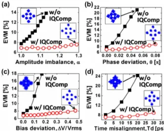
Fig. 4 depicts the back-to-back performance in terms of the error vector magnitude (EVM) versus the amplitude imbalance
, phase deviation , bias deviation , and time
misalignment with and without the proposed equalization scheme. The bias deviation is measured in unit normalized to
PENG et al.: COMPENSATION FOR I/Q IMBALANCES AND BIAS DEVIATION OF THE MZMs 105
Fig. 4. (a) EVM versus amplitude imbalance, (b) EVM versus phase deviation, (c) EVM versus bias deviation, whereV is the root-mean-squared amplitude of the input signal, and (d) EVM versus the time misalignment.
Fig. 5. Measured BER versus the OSNR for systems with the conventional one-tap equalizer and with our proposed I/Q compensation approach.
the root-mean-square (rms) voltage of the input signal . EVM, with its rigorous definition given in [3], is a measure of the signal quality and a lower EVM means a better perfor-mance. Note in this letter the curves labelled as “w/o IQComp” use the previous interleaved OFDM system [3], which locates the data at the odd-numbered subcarriers and, therefore, will suffer the interference resulted from the bias deviation, and equalize the received signal with the conventional one-tap equalizer. On the other hand, the “w/IQComp” curves utilize only the even-numbered subcarriers for data transmission and use the proposed I/Q compensation technique for equalization. During the experiments, 50 training symbols are used in both systems with and without the I/Q compensation technique. From Fig. 4, for all four different kinds of imbalances or bias deviation, the signal with our proposed technique is insensitive to these deleterious effects, while the signal without I/Q com-pensation strongly suffers from the imbalance interferences and thus its performance degraded rapidly as the imbalances or the bias deviation increase. Thus, it demonstrates that our approach provides a robust tolerance to a broad range of both the imbalances and bias deviation.
Fig. 5 shows the signal performances, in terms of the OSNR, after being transmitted through an uncompensated 800-km link of SSMF without I/Q imbalances and bias deviation at the transmitter. The proposed equalization, as well as the conven-tional one-tap equalization, has only 2.5-dB power penalty
Fig. 6. Required OSNR for BER= 10 versus the fiber distance with I/Q imbalances and bias deviation with and without our proposed scheme.
after transmission, thus proving the proposed technique can also compensate the CD impairment as well.
To show how the proposed scheme works when both the I/Q imbalances and fiber CD coexist in the system, we deliberately introduce some imbalances and transmit the signal in the uncompensated fiber loop. In Fig. 6, we measure the required OSNR at a bit-error rate (BER) of as a function of the transmission distance in the presence of the imbalances and
bias deviation with the parameters of , ,
, and ps. The dotted line
in Fig. 6 means the performance baseline when there are no imbalances and bias deviation. In back-to-back, the signal with I/Q compensation has a 2-dB improvement over the signal without I/Q compensation. After 800 km of uncompensated SSMF transmission, the transmission penalties for signals with and without I/Q compensation are 3 and 5 dB, respectively, which means the impacts of the I/Q imbalances are further enlarged during transmission. The net gain of our approach is found to be 4 dB after 800-km transmission with the deliberately introduced imbalances and bias deviation.
The experimental results demonstrate that our I/Q compen-sation can simultaneously overcome the impairments from the imbalances and CD, and has a great potential for the future DSP-based optical transmission system since it could relax or alleviate the monitoring circuit at the transmitter.
REFERENCES
[1] B. J. C. Schmidt, A. J. Lowery, and J. Armstrong, “Experimental demonstrations of electronic dispersion compensation for long-haul transmission using direct-detection optical OFDM,” J. Lightw.
Technol., vol. 26, no. 1, pp. 196–203, Jan. 1, 2008.
[2] C. Xie, “PMD insensitive direct-detection optical OFDM systems using self-polarization diversity,” in Proc. Optical Fiber Commun.
Conf., San Diego, CA, Feb. 2008, Paper OMM2.
[3] W. R. Peng, X. Wu, V. R. Arbab, B. Shamee, L. C. Christen, J. Y. Yang, K. M. Feng, A. E. Willner, and S. Chi, “Experimental demonstration of a coherently modulated and directly detected optical OFDM system using an RF-tone insertion,” in Proc. Optical Fiber Commun. Conf., San Diego, CA, Feb. 2008, Paper OMM2.
[4] X. Wu, L. Christen, B. Zhang, W.-R. Peng, J.-Y. Yang, L. Zhang, S. R. Nuccio, J. A. Jargon, A. E. Willner, and L. Paraschis, “Synchro-nization monitoring of I/Q data and pulse carving misalignment for a parallel-type RZ-DQPSK transmitter by measuring RF clock tone/low frequency power,” IEEE Photon. Technol. Lett., vol. 20, no. 24, pp. 2138–2140, Dec. 15, 2008.
[5] T. C. W. Schenk, E. R. Fledderus, and P. F. M. Smulders, “Perfor-mance impact of IQ mismatch in direct-conversion MIMO OFDM transceivers,” in Proc. IEEE Radio and Wireless Symp., Jan. 2007, pp. 329–332.