行政院國家科學委員會專題研究計畫 期中進度報告
兆級晶片系統前瞻技術研究--子計畫六:兆級晶片系統實
體整合之研究(2/3)
期中進度報告(精簡版)
計 畫 類 別 : 整合型
計 畫 編 號 : NSC 95-2221-E-002-372-
執 行 期 間 : 95 年 08 月 01 日至 96 年 07 月 31 日
執 行 單 位 : 國立臺灣大學電子工程學研究所
計 畫 主 持 人 : 張耀文
報 告 附 件 : 出席國際會議研究心得報告及發表論文
處 理 方 式 : 本計畫可公開查詢
中 華 民 國 96 年 06 月 29 日
行政院國家科學委員會補助專題研究計畫期中報告
※※※※※※※※※※※※※※※※※※※※※※※※※※※※
※
兆級晶片系統前瞻技術研究 ※
※ 子計畫六:兆級晶片系統實體整合之研究(2/3) ※
※
Physical Integration for Trillion-Transistor-Scale System-on-Chip
※
※※※※※※※※※※※※※※※※※※※※※※※※※※※※
計畫類別:□個別型計畫 ▓整合型計畫
計畫編號:NSC 95-2221-E-002-372
執行期間:95 年 8 月 1 日至 96 年 7 月 31 日
計畫主持人: 張耀文教授
計畫參與人員: 江哲維、陳東傑
陳信成、莊易霖、劉宏毅
執行單位:國立臺灣大學電子工程學研究所
中 華 民 國
96 年 5 月 27 日
兆級晶片系統前瞻技術研究
子計畫六:兆級晶片系統實體整合之研究(2/3)
Physical Integration for Trillion-Transistor-Scale System-on-Chip
計畫編號:NSC 95-2221-E-002-372
執行期限:95 年 8 月 1 日至 96 年 7 月 31 日
計畫主持人:張耀文教授 國立臺灣大學電子工程學研究所
一
、
中文摘要
在 此 計 畫 中 , 我 們 提 出 了 一 個 嶄 新 的
MP-tree 表示法來處理擁有大區塊(macro block)
的混合尺寸設計。基於二元樹的特性,MP-tree 可
以有效地並且有彈性地處理擁有許多不同限制的
大區塊擺置問題。對一給定的全域擺置結果,我們
所 提 出 的 大 區 塊 擺 置 器 將 會 最 佳 化 大 區 塊 的 位
置、降低最佳化所造成的大區塊位移、並保留晶片
的中心區域給標準單元(standard cell)的擺置與
繞 線 。 由 在 ISPD'06 placement contest
benchmark 上所進行的實驗,我們所提出的大區塊
擺置器與 Capo 10.2、NTUplace3、或 mPL6 的結
合可以在穩固性(robustness)與品質(quality)上
大幅度地勝過學術界頂尖的混合尺寸擺置器。例
如,此一結合的方法可以修正兩組由 NTUplace3 所
產生的非法擺置,以及七組由 mPL6 所產生的非法
擺 置 , 同 時 分 別 減 少 7% 與 4% 的 平 均 半 周 長
(HPWL)。
關鍵詞:平面規劃、擺置、智財模組
二、英文摘要(Abstract)
In this project, we present a new multi-packing tree (MP-tree) representation for macro placement to handle mixed-size designs. Based on binary trees, the MP-tree is very efficient, effective, and flexible for handling macro placement with various constraints. Given a global placement, our MP-tree-based macro placer optimizes macro positions, minimizes the macro displacement from the initial macro positions, and maximizes the area of the chip center for standard-cell placement and routing. Experiments based on the eight ISPD’06 placement contest benchmarks show that our macro placer combined with Capo 10.2, NTUplace3, or mPL6 for standard-cell placement outperforms these state-of-the-art academic mixed-size placers alone by large margins in both robustness and quality. For example, the combined method can fix two and seven illegal placements from NTUplace3 and mPL6, and further reduce their average half-perimeter wirelengths (HPWL’s) of the remaining legal placements by 7% and 4%, respectively.
Keywords: Floorplanning, placement, intellectual
property module
三、
背景和目的
Due to the use of IP (Intellectual Property) modules and embedded memories, a modern VLSI chip often
consists of a significant number of macros. Mixed-size placement, which places both macros and standard cells, becomes more and more popular for real-world applications. In particular, the number of macros in a modern system-on-chip (SOC) design is expected to increase dramatically in the future [14]. As a result, many mixed-size placement flows/algorithms are proposed in the literature [2–5, 7–12] recently.
According to the macro handling methods, we can classify the mixedsize placement algorithms into three types. The first type places macros and standard cells simultaneously. A disadvantage of this type is that a robust macro legalizer is needed since macros are not guaranteed to be overlap-free after the placement stage. Especially when the chip utilization rate is high, it is possible that no legal solution can be obtained. The simulated annealing based placers, Dragon [12] and mPG-MS [5], the min-cut-based placers, Feng Shui [3] and NTUplace [7], and the analytical placers, APlace [9], Kraftwerk [11], mPL [4], and NTUplace3 [8], belong to this type.
The second type places macros constructively. Macros are guaranteed to be overlap-free during the placement process. Although this type of placers is usually more robust to find legal solutions, the wirelength may be longer than those from the first type. The min-cut floorplacer, Capo [10], belongs to this type. The fixed-outline floorplanning is applied when necessary during the min-cut placement process to ensure legal positions for macros.
Because of the advantages of the third type placers, we adopt the two-stage mixed-size placement approach. Our work focuses on the first stage, macro placement, which is crucial for mixed-size placement since macro positions significantly affect the placement of standard cells and the final placement and routing quality.
四
、
研究方法
1.
Mixed-Size Placement
We adopt the two-stage mixed-size placement flow: (1) macro placement followed by (2) standard-cell placement. See Figure 1 for our mixed-size placement flow. After the circuit information is imported, a wirelength-driven global placement is applied to find global macro positions. Based on the given macro positions, our macro placer then determines the legal positions of macros in the chip region. With the objective of the macro displacement minimization, our macro placement algorithm results in better macro positions that lead to smaller wirelength in the later stage implicitly. The macro placement step plays an important role in the mixed-size placement. Finally, all macros are fixed and a standard-cell placer is then applied to place all standard cells in the available space.
Figure 1: Our mixed-size placement flow.
Our macro placement is based on a packing technique so we can easily find legal solutions even for the cases with large macros and/or a large number of macros. Also, many real-world constraints can easily be considered; for example, the macro orientations can be optimized and the spacing between macros for routing can be reserved, which are important for practical applications.
2.
Macro Placement
Our design strategy is to pack macros inside the given region and to reserve the center region for standard-cell placement and routing. Since macros are usually large and there are routing blockages above macros in real-world applications, the macros tend to block the routes if they are placed in the chip center. Further, by minimizing the macro displacement, we can keep the desired wirelength implicitly since the given global placement is optimized for wirelength.
The traditional packing floorplanning techniques cannot apply to the macro placement problem directly since they usually pack all macros to one corner. To overcome this problem, we propose a new multi-packing tree (MP-tree) floorplan representation to place macros along the given region boundary. We shall first consider the packing-tree floorplan representation.
2.1 Packing-Tree Floorplan Representation
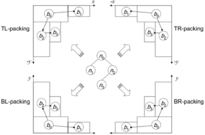
A packing tree is a binary tree for modeling non-slicing or slicing floorplans. Each node in the packing tree corresponds to a macro. There are four types of packing for a packing tree. BL-, TL-, TR-, and BR-packing packs the blocks to the bottom-left, top-left, topright, and bottom-right corners, respectively.
Figure 2 shows a packing tree and its corresponding four packing types. Let (xcorner, ycorner) be the coordinate of a corner (there are four corners in a rectangular region), (xi, yi) be the bottom-left coordinate of the block bi, and wi (hi) be the width (height) of the block bi. The coordinate of the root of a packing tree is at
• (xcorner, ycorner) for BL-packing, • (xcorner, ycorner − hroot) for TL-packing,
• (xcorner − wroot, ycorner − hroot) for TR-packing, and • (xcorner − wroot, ycorner) for BR-packing.
If node nj is the right child of ni, the block bj is
• the lowest adjacent block on the right with xj = xi + wi for BL-packing,
• the highest adjacent block on the right with xj = xi + wi for TL-packing,
• the highest adjacent block on the left with xj = xi − wj
for TR-packing, and
• the lowest adjacent block on the left with xj = xi − wj for BRpacking.
If node nj is the left child of ni, the block bj is
• the first block above bi with xj = xi for BL-packing, • the first block below bi with xj = xi for TL-packing, • the first block below bi with xj = xi + wi − wj for
TR-packing, and
• the first block above bi with xj = xi + wi − wj for BR-packing.
Therefore, given a packing tree, the x-coordinates of all blocks can be determined by traversing the tree once in linear time. Further, a y-coordinate can be computed using the contour data structure in amortized constant time, similar to the method used in [6]. So the complexity of transforming a packing-tree to the corresponding placement is amortized linear time. Note that B*-tree floorplan representation [6] is a BL-type packing tree.
Figure 2: A packing tree with its four types of packing. A packing tree handles only one direction of packing, and thus it is not suitable for our macro placement since all macros would be packed toward a chip corner. In the following section, we extend the packing tree to handle macro placement with placement constraints.
2.2 MP-tree Floorplan Representation
Since a packing tree always packs macros to a corner, we could apply the traditional hierarchical method by subdividing the chip into four regions, and create four packing trees to handle different regions. However, this approach has some limitations. First, the macros in a region must be placed inside the given region, which is over constrained because there is no real boundary between the regions. Further, assigning the regions for macros greatly affects the resulting placement because a macro cannot change its region once its region is assigned. As a result, we may not obtain a desirable placement because there is no interaction among different regions.
To implement the global optimization idea, we resort to the multipacking tree (MP-tree) to handle the global interaction among different regions. An MP-tree combines several packing trees for different corners. Figure 3 shows an example general MP-tree. There are k branch nodes in an MP-tree to integrate k + 1 packing subtrees. We use a right-skewed branch to integrate the packing subtrees for the purpose of easier implementation. By doing so, the packing order of the subtrees can be determined by the level of the parent node of the packing subtrees. With the depth-first search (DFS) order of the tree traversal for packing, the
smaller the level, the earlier the packing subtree packs blocks. If the parent of two packing subtrees is the same, the left packing subtree will be handled first. The general MP-tree can be used to model the placement in any rectilinear floorplan region with each packing subtree packing to one convex corner.
Figure 3: A general MP-tree.
The MP-tree structure directly induces a special hierarchical framework for the optimization of macro placement. Each packing subtree handles macros being packed to a corner, i.e., perform local optimization. A major drawback of the traditional hierarchical framework is that it lacks the global information for the interaction among subtrees (subproblems). Because of the branch structure in the MP-tree, unlike the traditional hierarchical framework, the interaction between different subtrees of an MP-tree is well preserved, facilitating the global optimization among all subtrees. It will be clear in Section 3 that the MP-tree leads to significantly better placement quality than that obtained by the traditional hierarchical method using independent packing trees.
Figure 4: A packing example for an MP-tree with a BL-packing subtree and a BR-packing subtree. Adding a new block b4 to the placement, we search the contour and update it with the top boundary of the new block.
To transform an MP-tree to its corresponding placement, each x-coordinate of a block can be determined by a DFS traversal, and the x-coordinate definition is the same as the packing tree. To compute y-coordinates, we keep two contours, the bottom contour and the top contour, which are initialized according to the bottom side and the top side of the given rectilinear region, respectively. Both BL- and BR-packing subtrees use the bottom-contour data structure, while the TL- and TR-packing subtrees use the top-contour one. The packing subtrees that use the same contour data structure always generate overlap-free placement results since the contour reserves the spaces of the traversed blocks. BL-/BR-packing subtrees, however, may overlap with TL-/TR-packing subtrees, and thus we should discard this kind of infeasible solutions. Figure 4 gives a packing example for an MP-tree with a BL-packing subtree and a BR-packing subtree. The packing order is b1, b2, b3, and b4. Adding a new block b4 to the placement, we search the contour and update it with the top boundary of the new
block. It is clear that no overlap will occur when we process BL- and BR-packing subtrees.
2.3 Operations on MP-tree
We define the perturbation operations of the MP-tree for use in simulated annealing. An MP-tree is perturbed to get another MPtree by the following operations:
• Op1: Rotate a block or a cluster. • Op2: Resize a cluster.
• Op3: Move a node in a packing subtree to another place.
• Op4: Swap two nodes within one or two packing subtrees.
• Op5: Swap two packing subtrees.
For Op1, we rotate a block or a cluster for a tree node. For Op2, we change the clustering dimension of a cluster. Note that Op1 and Op2 do not affect the MP-tree structure. For Op3, we select a node from a packing subtree, and move it to another place of the same or different packing subtrees. For Op4, we select two nodes from one (two) packing subtree(s), and swap them. For Op5, we swap two packing subtrees, and the packing order of two packing subtrees are exchanged. Note that the branch structure of an MP-tree is fixed and does not change by any type of operation.
2.4 Evaluation of a Macro Placement
To evaluate the quality of a macro placement solution, the cost of a macro placement F is defined as follows:
( )F
α
Aβ
Wγ
Dδ
O, Φ = + + +where A is the macro placement area, W is the total wirelength, D is the total macro displacement, O is the vertical overlap length, and α , β, γ, and δ are user-specified weighting parameters. The macro placement area, wirelength, macro displacement, and vertical overlap length are explained in the following.
The macro placement area is the area under the bottom contour plus the area above the top contour. As shown in Figure 5(a), the contours are plotted by dashed lines, and the corresponding macro placement area is shown in Figure 5(b). Minimizing the macro placement area can make more space for the standard cells in the central region of the chip. By doing so, the routing between standard cells will be easier, and thus the routed wirelength will be smaller.
Figure 5: (a) A macro placement solution and its top and bottom contours. (b) The corresponding macro placement area.
Cost D is the total macro displacement, which is defined by
2
(| '
i i| | '
i i|) ,
blocks
D
=
∑
x
−
x
+
y
−
y
where (xi, yi) is the initial position of macro bi, and (xi’, yi’ ) is the current position of macro bi during simulated annealing. The quadratic penalty can prevent a single macro
from having a large displacement.
Our MP-tree representation can guarantee no overlaps between the top and the bottom packing subtrees. However, there may exist vertical overlaps between the top contour and the bottom contour. The penalty cost O for the vertical overlap can guide the simulated annealing to find a non-overlap solution.
2.5 Macro Placement Flow
Figure 6 shows the flow for our MP-tree macro placer. After reading LEF/DEF files, we cluster the macros for the designated performance macros, and the cluster dimension is initialized with the one closest to square since the square dimension usually leads to better results. Then, we create an MP-tree with its number of packing subtrees equal to the number of the corners in the placement region. If the region constraints are given, we need to create four subtrees for each region. Each macro/cluster corresponds to a node in a packing subtree. If an initial macro placement is given, we can assign the initial packing subtree to which a node belongs according to the nearest corner for the macro. Otherwise, we randomly set the initial packing subtree to which a node belongs. Each packing subtree is then initialized as a complete binary tree.
Figure 6: Our MP-tree macro placement flow.
Simulated annealing is used to find the desired macro placement. We perturb an MP-tree to get another MP-tree by the aforementioned operations described in Section 2.3. After perturbing, we fix the tree structure to satisfy the given macro placement constraints, pack the MP-tree, evaluate the macro placement, and decide whether we should accept the new solution or not according to the difference of the macro placement quality and the current temperature of simulated annealing. Then, the MP-tree is perturbed again. The simulated annealing continues until the solution is good enough or no better solution can be found, and all positions of blocks/clusters are determined. Then, the positions of macros inside a cluster can be computed according to the matrix dimension of the cluster.
Finally, we adjust the spacing between macros. If the demand of the routing resource between two macros is higher than the original spacing, we add more space between the two macros; otherwise, we can reduce the original spacing to make the macro placement area smaller. We also orientate macros by horizontal/vertical flipping to make the pins closer to the chip center. Then, we fix all macros and report the final macro placement solution.
3.
Experimental Results
To show the effectiveness and robustness of MP-tree, we conducted four experiments on an Opteron 2.6GHz machine. We used three state-of-the-art publicly available academic mixed-size placers, NTUplace3 [8], Capo 10.2 [10], and mPL6 [4]. Note that NTUplace3 achieves the best published results in most public benchmarks [8], Capo is the best min-cut based placer and mPL6 obtains the best quality considering wirelength and density at the 2006 ISPD Placement Contest [1]; both NTUplace3 and mPL6 are analytical placers. Table 1 shows the statistics of the ISPD’06 benchmarks.
Table 1: The statistics of the ISPD’06 benchmarks.
3.1 Comparison between MP-tree and Packing
trees
This experiment studies the difference between the MP-tree and the independent four packing trees described in Section 3.2. The method of using four packing trees is a simple extension to macro placement for a rectangular chip. We divided a chip into four sub-regions and created four different BL-/BR-/TL-/TR-packing trees in the corresponding sub-regions. Notice that although this extension for packing trees still can handle macro placement in a chip, it has many limitations; for example, it is much harder to deal with the region constraints that cross different regions.
We used the ISPD’06 benchmarks with the 90% chip utilization rate, and the results are shown in Table 2. From the results, we observed that the MP-tree is more robust in finding legal placements for all benchmarks while the method with four packing trees cannot. For those benchmarks with legal placements, the MP-tree can further reduce the average HPWL by 8% under comparable running times, which shows the effectiveness of the MP-tree.
Table 2: The resulting HPWL’s of using the MP-tree and four packing trees for macro placement (utilization rate = 90%). NR: No legal results can be obtained.
3.2 Integration with Other Placers
In addition to NTUplace3, we also integrated our MP-tree with Capo 10.2 and mPL6, which are based on the min-cut and analytical placement techniques, respectively. Table 3 shows the results without and with the MP-tree based on the ISPD’06 benchmarks. Again, we used the 90% chip utilization rate for all circuits. Capo is robust in finding legal placements since macro positions are guaranteed to be overlap-free during the global placement. However, the quality is not good. Integrated with the MP-tree, Capo 10.2 reduced the average HPWL by 12% than that without the
MP-tree. We tried several times, but mPL6 alone could not obtain legal solutions for seven circuits. With the MP-tree, however, mPL6 can obtain legal solutions for all circuits. This shows that the MP-tree is robust in finding legal solutions.
Table 3: The resulting HPWL’s and CPU times for different placers without (“w/o”) and with MP-trees (“MPT”) (utilization rate = 90%). NR: No legal results can be obtained.
五、成果 (Publications)
1. T.-C. Chen, Z.-W. Jiang, T.-C. Hsu, H.-C. Chen, and Y.-W. Chang, "A high quality analytical placer considering preplaced blocks and density constraint," in Proceedings of IEEE/ACM International Conference on Computer-Aided Design (ICCAD-2006), pp. 187--192, San Jose, Nov. 2006. (Received
the highest score in the partitioning / floorplanning / placement track)
2. W.-P. Lee, H.-Y. Liu, and Y.-W. Chang, "Voltage island aware floorplanning for power and timing optimization," in Proceedings of IEEE/ACM International Conference on Computer-Aided Design (ICCAD-2006), pp. 389--394, San Jose, Nov. 2006.
3. I.-J. Lin, T.-Y. Lin, and Y.-W. Chang, ``Statistical circuit optimization considering device and interconnect process variations," to appear in Proceedings of ACM International Workshop on System Level Interconnect Prediction (SLIP-2007), Austin, TX, March 2007
4. T.-C. Chen, Y.-L. Chuang, and Y.-W. Chang, "X-architecture placement based on effective wire models," in Proceedings of ACM International Symposium on Physical Design (ISPD-2007), pp. 87--94, Austin, TX, March 2007. (best paper
nominee; received the highest score)
5. H.-Y. Liu, W.-P. Lee, and Y.-W. Chang, "A provably good approximation algorithm for power optimization using multiple supply voltages," to appear in Proceedings of ACM/IEEE Design Automation Conference (DAC-2007), San Diego, CA, June 2007.
6. T.-C. Chen, P.-H. Yuh, Y.-W. Chang, F.-J. Liu, and D. Liu, " MP-trees: a packing-based macro placement algorithm for mixed-size designs," to appear in Proceedings of ACM/IEEE Design Automation Conference (DAC-2007), San Diego, CA, June 2007. (received the 2nd highest score out of 52 papers in
the physical design and manufacturability track)
7. H.-Y. Liu, W.-P. Lee, and Y.-W. Chang, "A provably good approximation algorithm for power optimization using multiple supply voltages," to appear in Proceedings of ACM/IEEE Design Automation Conference (DAC-2007), San Diego, CA, June 2007
8. T.-C. Chen and Y.-W. Chang, "Routability-driven and optical proximity correction-aware multilevel full-chip gridless routing," accepted and to appear in IEEE Trans. Computer-Aided Design, Vol. 26, No. 6, June 2007.
9. T.-C. Chen, Y.-W. Chang, and S.-C. Lin, "A new multilevel framework for large-scale interconnect-driven floorplanning," in minor revision, IEEE Trans. Computer-Aided Design. (TCAD #2615)
10. T.-Y. Ho, C.-F. Chang, Y.-W. Chang, and S.-J. Chen, ``Multilevel full-chip routing for the X-based architecture," in minor revision, IEEE Trans. Computer-Aided Design. (TCAD #2996)
11. T.-C. Chen, Z.-W. Jiang, T.-C. Hsu, H.-C. Chen, and Y.-W. Chang, ``NTUplace3: An analytical placer for large-scale mixed-size designs with preplaced blocks and density constraints," in revision, IEEE Trans. Computer-Aided Design 12. W.-P. Lee, H.-Y. Liu, and Y.-W. Chang, “An ILP Algorithm for
Post-Floorplanning Voltage-Island Generation Considering Power-Network Planning,” submitted to ICCAD-2007
13. H.-C. Chen, Y.-L. Chuang, Z.-W. Jiang, Y.-W. Chang, ``A High-Quality Transitive-Closure-Graph-Based Macro Placer,” submitted to ICCAD-2007
14. T.-C. Chen, M. Cho, D. Z. Pan, and Y.-W. Chang, “Metal-Density Driven Placement for CMP Variation and Routability,” submitted to ICCAD-2007
15. H.-Y. Chen, S.-J. Chou, S.-L. Wang, and Y.-W. Chang, “Novel Wire Density Driven Full-Chip Routing for CMP Variation Control,” submitted to ICCAD-2007
六
、
參考文獻
[1] ISPD 2006 Placement Contest.http://www.sigda.org/ispd2006/contest.html.
[2] S. N. Adya and I. L. Markov. Combinatorial techniques for mixed-size placement. ACM Transactions on Design Automation of Electronics Systems, 10(5), Jan. 2005. [3] A. R. Agnihotri, S. Ono, C. Li, M. C. Yildiz, A. Khatkhate,
C.-K. Koh, and P. H. Madden. Mixed block placement via fractional cut recursive bisection. IEEE Trans.
Computer-Aided Design, 24(5):748–761, May 2005. [4] T. Chan, J. Cong, J. Shinnerl, K. Sze, and M. Xie. mPL6:
Enhanced multilevel mixed-size placement. In Proc. of ACM ISPD, pages 212–214, San Jose, CA, Apr. 2006.
[5] C.-C. Chang, J. Cong, and X. Yuan. Multi-level placement for large-scale mixed-size ic designs. In Proc. of IEEE/ACM ASP-DAC, pages 325–330, Kitakyushu, Japan, 2003. [6] Y.-C. Chang, Y.-W. Chang, G.-M. Wu, and S.-W. Wu.
B*-trees: A new representation for non-slicing floorplans. In Proc. of ACM/IEEE DAC, pages 458–463, Los Angeles, CA, June 2000.
[7] T.-C. Chen, T.-C. Hsu, Z.-W. Jiang, and Y.-W. Chang. NTUplace: a ratio partitioning based placement algorithm for large-scale mixed-size designs. In Proc. of ACM ISPD, pages 236–238, San Francisco, CA, Apr. 2005.
[8] T.-C. Chen, Z.-W. Jiang, T.-C. Hsu, and Y.-W. Chang. A high-quality mixed-size analytical placer considering preplaced blocks and density constraints. In Proc. Of IEEE/ACM ICCAD, San Jose, CA, Nov. 2006.
[9] A. B. Kahng and Q. Wang. A faster implementation of APlace. In Proc. of ACM ISPD, pages 218–220, San Jose, CA, Apr. 2006.
[10] J. Roy, D. Papa, A. Ng, and I. Markov. Satisfying whitespace requirements in top-down placement. In Proc. of ACM ISPD, pages 206–208, San Jose, CA, Apr. 2006.
[11] P. Spindler and F. M. Johannes. Fast and robust quadratic placement combined with an exact linear net model. In Proc. of IEEE/ACM ICCAD, San Jose, CA, Nov. 2006.
[12] T. Taghavi, X. Yang, B.-K. Choi, M. Wang, and M. Sarrafzadeh. Dragon2006: Blockage-aware
congestion-controlling mixed-size placer. In Proc. of ACM ISPD, pages 209–211, San Jose, CA, Apr. 2006.
[13] N. Viswanathan and C. C.-N. Chu. Fastplace: Efficient analytical placement using cell shifting, iterative local refinement and a hybrid net model. In Proc. of ACM ISPD, pages 26–33, Apr. 2004.
[14] E. Wein and J. Benkoski. Hard macros will revolutionize SoC design. EETimes Online, Aug. 2004.
http://www.eetimes.com/showArticle.jhtml?articleID=268070 55.
[15] G.-M. Wu, Y.-C. Chang, and Y.-W. Chang. Rectilinear block placement using B*-trees. ACM Transactions on Design Automation of Electronics Systems, 8(2):188–202, 2003.