2006IEEEInternational Conferenceon Systems, Man,andCybernetics
October 8-11, 2006, Taipei, Taiwan
A
Robust
Speech Enhancement
System
for Vehicular
Applications
Using
H.
Adaptive Filtering
Chieh-Cheng Cheng, Wei-Han Liu, Chia-Hsing Yang, and Jwu-Sheng Hu, Member, IEEE
Abstract-This work proposes a novel and robust adaptive
speech enhancement system, which contains both time-domain and frequency-domain beamformers using H,O filtering
approach in vehicle environments. A corresponding
microphone array data acquisition hardware is also designed
and implemented. Traditionally, mutually matched microphones areneeded, but this requirementis notpractical.
To conquerthis issue, theproposedsystemadapts the mismatch
dynamics to allow unmatched microphones to be used in an
array.Furthermore,toachieveasatisfactory speechrecognition performance, the speech recognizer is usually required to be retrained for different vehicle environments due to different noise characteristics and channel effects. The channel effect
usuallycausesthemodelingerrorinachannel recoveryprocess because of the long channel response. The proposed system
using the H,, filtering approach, which makesno assumptions
aboutnoise and disturbance, is robust to the modeling error.
Consequently, the proposed frequency-domain beamformer
providesasatisfactory performancewithout the needtoretrain thespeechrecognizer.
I. INTRODUCTION
T HE use of mobile phones and electronic systems in vehicles is becoming increasing. Considering driving safety and convince, mobile phones and many in-car electronicsystems suchas global positioning system(GPS), CD, air conditioner, etc. should not be accessed by hands whiledriving. Consequently, intelligenthands-free interfaces with speech recognition were proposed in recent years. However,the echo of the far-end speechandenvironmental noises degrade the recognition performance and result in a low acceptance of hands free to consumers. Therefore, methods such as single-channel [1]-[2] and multi-channel speechenhancementtechniques [3]-[8]have beenintroduced. Although single-channel based methods can reduce the hardware complexity, the performance degrades due to variousproblems[3].
Jwu-ShengHuiswithDepartmentof ElectricalandControl Engineering, National Chiao Tung University, Hsinchu 300, Taiwan, ROC. (e-mail:
Chieh-Cheng Cheng is with Department of Electrical and Control Engineering, NationalChiao TungUniversity, Hsinchu 300, Taiwan, ROC. (e-mail:[email protected])..
Wei-Han Liuis with Departmentof ElectricalandControl Engineering, National Chiao Tung University, Hsinchu 300, Taiwan, ROC. (e-mail:
Chia-Hsing Yang is with Department of Electrical and Control Engineering,NationalChiaoTungUniversity, Hsinchu 300, Taiwan, ROC. (e-mail: chyang.ece92ggnctu.edu.tw)
To overcome the limitation, the microphone array based noisesuppressionapproaches,such as Frostbeamformer[4], robust adaptive beamformer [5], and generalized sidelobe canceller (GSC) [6] are proposed. However, these methods still suffer from several non-ideal factors. For example, the microphones are required to be mutually matched and no coherentinterferencesignalexists. Dahlet.al.[7]proposeda finite impulse response (FIR) based normalized least-mean-square (NLMS) filtering approach to perform indirect microphone calibration and to minimize the sound signal distortiondue to channeleffectby usingapre-recorded speech signal and a desired signal acquired when the environment was quiet. Because the variation between pre-recorded signals and the desired signal contain useful informationabout thedynamicsof channel andmicrophones' characteristics, this methodoutperforms other un-calibrated algorithms in real applications [8]. However, theFIR filter using the finite number of taps is unlikely to completely characterize the channeldynamics [9].Moreover,the NLMS based formulation assumes the disturbance is uncorrelated to the source, zero mean and Gaussian distributed. Thesewill limit theperformance of speechenhancement.
Onthe contrary,the proposedHo, filtering approaches are robusttothemodelingerrorcaused by finitetaplength of FIR filters and have no assumption made regarding the characteristics of environmental noises [10]-[11]. Furthermore, the method of using the pre-recorded signals and thedesiredsignalcansuppressthegainfrom noisestothe output and the characteristics of received multi-channel signals canbe automatically adjustedtothose of thedesired signal. Therefore, extra training processes for speech recognizerinvehicles are notneededin this work. Forspeech communicationviahands-free mobile phones,atime-domain beamformer using
H,.
isproposed to produce a more clean and undisturbed speech waveform. Secondly, for speech recognition applications, a frequency-domain beamformer using H,x, is proposed to reduce the effect of uncertainty in signal transformation between the time-domain and the frequency-domain bytreating several frames as a single block. Theproposed approaches using two microphones outperform dual channel delay-and-sum beamformer with a high-pass filterintroduced in [3].Different choices of the number of the microphone are also comparedThe remainder of this paper is organized as follows. The proposed speech enhancement system and the microphone
Fig. 1.Overall system architecture Amplifiers andFilters
PowerControl AnalogSwitch Fig.2.Microphonearra' array data acquisition hardware designed are introduced in section 2. Section 3 presents the two proposed HI, filtering based beamformers in both time and frequency-domain. Several representative experiments in a real vehicle are shown and the performances of experimental results are discussed in section 4. Finally, the conclusion is made in the last section.
II. SPEECHENHANCEMENTSYSTEMANDMICROPHONE ARRAY DATAACQUISITION HARDWARE IMPLEMENTATION
Theoverall system architecture can be illustrated as Fig. 1 andcanbedividedinto twosub-systems.Thefirstsub-system consists of a microphone array whose geometry can be flexiblyarrangedandadataacquisitionelectronics prototype designedbythis work. The main feature of thisdesignis that the system can digitalize the received sound signals and transmit them in real-time via USB interface. The second sub-system represents thespeechenhancementsystem.
A. Microphone Array andMicrophone ArrayData AcquisitionBoard
The microphone array consists of M omni-directional condenser microphones and a headset microphone. The frequency response ofthemicrophoneisrangedfrom50Hzto 16kHz. The microphone array acquisition board made ofa four-layer boardcanbedividedinto threeparts.
Inthe firstpart,the microphonesignals areamplifiedand
Sample and.Hold
The Socket for Connecting
AIDConverter withUSBInterfacePlatform
ydataacquisition board
filtered by six amplifiers and six band-passfiltersdesigned to take the microphone sensitivity and anti-aliasing into consideration. The gain of the M microphones and the headset microphone are set to 60dB and20dB individually. The second partcomprises sixsample-and-hold circuits (S/H), one analog switch circuit, and one analog-to-digital (A/D) converter. The third part contains the control and data transmission lines which are controlled by the universal serial bus (USB) interface. Through the control line, the USB interface platform can control the timing of the sample-and-hold circuits, switch, and A/D converter. The switching frequency and the timing of the system can be selectedflexibly,and thesampling frequency in this work is setto 8kHz.The converted 16-bitdigital data are transmitted inreal-time through the USB interface.
Mie.rnnhnni- Arrnv H4enckce-t Min.ronhone
The pictureofthemicrophonearraydataacquisition board is shown in Fig. 2. Fig. 3 shows the installation of the array inside the vehicle. Note that the headsetmicrophone is used only for collecting the desiredsignal, i.e., the userdoesnot need the headset microphoneduring the onlineapplications.
B. SpeechEnhancement System
This system can be separated intotwo stages, silent stage andspeech stage, by a voice activity detector(VAD) which can distinguish whether the received signals contain speech signals or not. The voice activity detectionalgorithm canbe found in reference [12]. If the result of VAD isequaltozero, which meansthatnospeechexists,the systemwillberunin thesilent stage. When the result of VAD isequaltoone,the systemcouldbeswitchedtothespeechstage.
Thepre-recorded speech signals showninthesilent stage inFig. 1 are collected whentheenvironmentis quietand the speaker is atthe desired location. The pre-recorded speech signals contain both the characteristics ofmicrophones and the acoustical characteristics of the desired location. The desiredsignal, d(n),is derived fromaheadsetmicrophoneat the same time when the pre-recoded speech signals are collected. Since the headsetisclosetothemouth,the desired signals contain little channel distortion. The desired signal onlyneedstobe collected when thedesiredlocationvaries,so the headset microphone is not needed during the online applications. In the silent stage, the environmental noise signals without speech signals are recorded online. The environmentalnoisesignalsareassumed to beadditive,sothe signals received when a speaker is talking in a noisy environmentcanbeexpressedas alinearcombination of the speech signals and the environmental noises. Therefore, in this stage, the system combines the online recorded environmental noise signals,
n,
(n),* nM (n) , with the pre-recorded speech signals,s1(n),..s,
5M(n),
to construct trainingsignals,
x (n),,x,
(n) The training signals are used to adapt theweighting vectorusingHo.
basedadaptive filtering approach. Inthe speech stage, thetrainedweighting vector is passed to the lower beamformer to purify and recoverthe noisyreceivedsignals,y,
(n),'YM
(n).
III. PROPOSED SPEECH ENHANCEMENTAPPROACHES A. Time-Domain Beamformer Using
H,.
Filtering ApproachBased on the system architecture shown in Fig. 1, the formulation ofmicrophonearrayspeech enhancement system canbeexpressedasthe followinglinearmodel:
d(n) =XT (n)w+e(n) (1)
In this work, italics fonts represent scalars, bold italics fonts represent vectors, and bold upright fonts represent matrices. M denotesthenumberofmicrophones, P denotes
the filter order ofeach microphone, and the superscript T denotes the transpose operation. d(n) is the desired signal and x(n)=[xl(n) ... XM(n)]T is a MP x 1 training signal
vector.
xi
(n)=[xi
(n) ...xi
(n-P +1)] is a Px1 trainingsignal vector. In addition, w is the MPx1 unknown filter coefficient vector ofthe time-domain beamformer that we intent to estimate. e(n) is the unknown estimation disturbance,which may also includemodelingerror.
To apply the adaptive Ho. filtering algorithms, the linear model, asin(1),istransformed into its state space form:
w(n+1)= w(n)
d(n)=XT(n)w(n)+e(n) with w(n)=w
The criterioninthesenseofHo. is:
min max J=-I
,2,u-I
ww)2
w(n) (e(n),w(0))2
I N .
2+E-I
w-v(n)le(n)2
2n=O
(3)
where
,u
is a weighting parameter and wi'(n) is the MPx1estimated filter coefficient vector.
H'2
denotes the square ofthe 2-norm. According to [13], the solution of uiv(n) can be
approximated bythe iteration: M-l(n+1)=M '(n)+x(n)xT (n) 21
-XT (n))
wi(n+1)= i(n)+M(n)x(n)
(d(n)
(n)iv
(1+XT(n)M(n)x(n))
(4)
(5)
(6) w'(O) 0, M-1(0) =
(,uO-
_,2)L
where M(n) is an MPxMP matrix and ()-l denotes the
matrix inverse operation. In order to ensure that M(n)
remains positive definite, ; should be chosen such that
M-'
(n)+x(n)xT (n)-;-21>0.For this reason, 4is selectedas gjeig(M -l(n)+x(n)XT (n)) during the iteration, where
eig(z) denotes the maximum eigenvalue ofz and 5>1 in
ordertokeep , greaterthanthe minimumvalue.
Theadaptation ofthefiltercoefficientvectorisperformed
in the silent stage. When the system is switched to speech
stage, theadaptationstops and the filtercoefficientvectoris passed to lower beamformer. The output of the speech purificationsystemcanbecalculatedby
5(n)= yT(n)wv(n)
(7)
where P(n) is the purified result, and y(n) is the (2)
MPx1online recordedpolluted speech signalvectoracquired by the microphone array.
B. Frequency-Domain Beamforming Using
H,
Filtering ApproachThe unknown estimation disturbance at frame k and frequency co can be written as:
E(w, k)
-D(co,
k)-WH(co,
k)X(co, k)
(8)
with W
(o),k)-=W
(o))
whereD(co, k)is the desired signal inthe frequency-domain and W(co) denotes the Mx1 unknown weighting vector at frequency co . The superscript H denotes Hermitian
operation. X(w,k) , N(co,k) and S(co,k) represent the frequency-domaintraining signal vector, the online recorded environmental noise vector, and the pre-recorded speech signalvector,respectively.
Ingeneral, the windowsizeinthe STFT hastoequaltothat in ASR in ordertoobtain a more accurateresult. However, the window size may be too small to capture the acoustic channel response. For this reason, a previous work [8] proposed an approach calledsoft penalty frequencydomain block beamformer (SPFDBB). However, the NLMS algorithmused inthat work[8] limits itsperformance dueto its inherent assumptions on the disturbances and channel dynamics. Consequently, the H. based
filtering approach
is adoptedtoimprovetheperformancefurther. TheH,,
iterative solutionscanbe shownas:W(f,k
+1) =W(co,k)+K(co,k)LDL (,k)-H(o,k)W(co,k)] (9)
K(co,k)=
P(o,k)H
(co,k)(I+H(o,k)P(co,k)H"(w,k))
1(10) P-(co,k+1)=P-Pl(c,k)+HH(w,k)H(co,k)-
-2IM
(I
1)
k k+L-1 H
lH(co,k)= X(c,k) X(,k+L -1) p XS(Co, j)
Lj=k k+L-1I
DL(a,k)= D(co, k) D(c,k+L-1) pAZ2ED(woj)
L j=k
P
(C)l)
=,OIM
andW(co,0)
=[o
0 ...0]T
(12) (13) (14) where W(co)denotes an unknown weighting vectors, the
superscript * denotes the complex
conjugate,
andH(wo,k)
is a (L+1)x M dimensional matrix at kth block.IM
is an identity matrix with dimension M xM. The value of 4during the iteration is chosen as
ig(P-T'(co,k)
+HH(w,k)H(co,k)) to keep 4 greater than the minimum value.Consequently, the purified output signal at k th block can beobtained by the following equation:
A(m,k)=WH(co,k)X(co,k) (17)
where
5(c,k)
andkQo,
k) is the M x L online recorded polluted speech signal matrix. The step k is chosen as 0,L, 2L, 3L, to perform the adaptation process every L frames.IV. EXPERIMENTALRESULTS A. Experimental Conditions and Parameters
The experiment was performed on passenger seat of a mini-van vehicle instead of thedriver's seat due to the driving safety consideration. A uniform linearmicrophone array of five un-calibrated microphones with 0.07 m spacing is mounted in front of the passenger seat. In addition, the distance between themicrophonearrayand the mouth of the speakerwhosits in passengerseatisabout 0.62m. Toshow theperformanceof theproposedapproaches, 341pairsof the vehicleidentification numbers and ten conditions(C1 -C10 of TableI)wereused. Theaverage SNR's in the tenconditions are shown in Table I and a music piece containing vocal sound isplayed repeatedly bysixbuild-inloudspeakers when the in-car audio system is tumed on. The desired signal utilized in this experiment is derived from the headset microphone which contains lowest channel distortion. The first and second microphones are utilized for dual microphone case (M=2) and the first, second, and third microphones are used when M =3 and so on. For
comparison purpose, thedelay-and-sumbeamformer with a high-pass filter(DS+HP) introduced in[3]isimplemented.
B. Time-DomainPerformanceEvaluation
Instead of using signal to noise ratio (SNR), two performance indices, signal recover ratio (SRR) and noise
TABLE I
TEN EXPERIMENTALCONDITIONSANDISOLATEDAVERAGE SNR Powerof In-car AudioSystem Off Off Off Off Off Average SNR(dB) 4.20 2.84 2.72 -1.90 -3.04 Condition Number C6 C7 C8 C9 CIO Condition Number C1 C2 C3 C4 CS Speed 20 Km/hr 40 Km/hr 60 Km/hr 80 Km/hr 100 Km/hr Speed 20 Km/hr 40 Km/hr 60 Km/hr 80 Km/hr 100 Km/hr Powerof In-car AudioSystem On On On On On Average SNR(dB) -0.08 -2.19 -2.28 -4.75 -5.40
=
=
=
=
power ratio (NPR), are defined to evaluate the degree of signal distortion and noise suppression. This is because a higher SNR does not imply that the signal distortion is low. SRRis defined as:
SRR(n) cov((c(n), (w(n)T s(n))))
jcov(d(n), d(n))x
co4v(w(n)
Ts(n)), (w(n)T s(n))) (18)where cov(.) is the covariance operation. Further, NPR is definedas: NPR(n)= j
[w(n)T
n(n)4
/,
n7(n) n=l n=l 0. 0. 0.7 0.6 c 0.5 0.4 0.3-0.2 0.1 (19) where V in(19)denotes thelengthofthedesiredsignal.SRR is defined as thecorrelation coefficient betweenthe desired signal, and therecovered signal (w(n)T s(n)). Consequently, ahighervalue of SRRmeans abetter speechrecovery. NPR represents the ratio of the noise power after beamformer processing (w(n)T n(n)) to thenoise powermeasured at the silent stage. The smaller value of NPR represents a more clean speech signal. The order of the time-domain beamformerusing Ho, filtering approachwas setto 128, and Po and ; were set to0.9 and 0.95individually.
The values of SRR and NPR after the DS+HP and time-domain beamformer usingHR,
filtering technique for the ten testing conditionsareillustrated in Fig. 5. As shown inFig. 5(a) and Fig. 5 (b),the SRR's of the proposed approach is higher than those of the DS+HP when two microphones are utilized includingthe cases when the in-caraudiosystemisturnedon (conditionsC6toC10).This is because theproposedsystem can recover the channel distortion and is robusttomodeling error.Moreover, thehigh-passfilter in DS+HPsuppresses the magnitudeoflowfrequencycomponentsof the speechsignal, which may decreasethe SRR further. The values of NPR of theproposed method alsooutperformthe traditional DS+HP inconditionsCl
toC(10.
The values ofNPR in C6 toC(10are larger than those inCl
to C5 becauseturning on the in-car audio system raises the complexity of the noise. The improvement of SRR and NPR are consistent with the number ofmicrophone used. It means a larger number of microphones couldprovide a better sound quality.0.7 0.4 0.4 0.3 0.2 0.1 -E- DS+HP --M=2 M=3 Ig M=4 -E&-M=5 ---e- DS+HP -6 M=2 -l(-M=3 -A4 M=4 -e M=5 6 C7 C8 C9 Conditions (b) SRR's of conditions C6toCIO. CIo 0.8r -e-DS+HP -O- M=2 - M=3 -A-M=4 M-5 0.21
0°
'
0 0.7 0.6 a-0.4 0.1 ol 1 C2 C3 C4 Conditions (c)NPR'sof conditions C1 to C5 C5 -M=2 M=3 -*--A-MM-34---=----
----
--E-tM- -C6 C7 C8 C9 Conditions (d)NPR'sof conditions C6toC 10 Fig. 5. SRR's and NPR's of conditions C1 toC1OC1o
C. Frequency-DomainPerformanceEvaluation
The resultsof thefrequency-domain beamformer using
H,.
ilitenng approact
areuirectiy
ueilverec to
abencnmark
speechrecognizer,HTK [14]. Inthe experiments,
pao
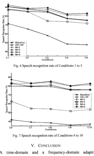
and , weresetto0.9 and 0.95individually and the soft penalty A is setto 2. In addition, the frame number L is set to 40. The window contains 256 zero padded samples and a 32ms speech signal whichgives atotal of 512 samples. The best possible recognitionrateusing the desired signal is 97.15%. Abaseline of therecognition rate using the first microphone only is established. As shown in Fig. 6 and 7, the baselineperformance
is pooras expected. When only the car noises C4 C5 exist (conditionsCl-C5),
the DS+HP can improve the recognitionrate in 15.52% to25.25% range compared with C5. the baseline. Because the DS+HP only attempts to suppressolC 1 C2 C3 Conditions (a)SRR'sofconditionsC I to . . * 0.6[ a.0.4 0. ---r.) ---0.8
the noise signals instead of dealing distortion, the performance cannotbe sat recognizer is re-trained. As indicate improvement using the proposed met becomes more significant when the env higher. The improvements are more si, music isturnedon(Fig. 7). The recogniti drops because it can only suppress a Sr
wideband music signal. Comparing Fig proposed method maintains a si performanceat avehiclespeedwithoutar background. 91 ct .._80 xa70 B0 a) (o"50 40[ C1 90 ae- 80-a) tr o70 : a 60 40 a) v)50 40 I--*- Baseline -% DS+HP -+- M=2 -_- M=3 -0- M=4 =5 C2 C3 Conditions
Fig.6Speechrecognitionrateof Con
,' ----
-with the channel
.. Pr , 1 ,1 REFERENCES
istactoryunless the [1] s. F. Boll, "Suppression of acoustic noise inspeech using spectral d by Fig. 6, the subtraction," IEEE Trans. Acoust. Speech, Signal Processing, vol.
[hod over DS+HP [2] A. Kawamura, Y.ASSP-27,pp. 113-120,Apr.liguni,and Y. Itoh,1979. "A noise reduction method based ironmental noise iS on linear prediction with variable step-size," IEICE Tran.
gnificant when the Fundamentals,vol.E88-A,no.4, pp.855-86lApril2005.
ionrate for DS+HP [3] s. Ahn and H. Ko, "Background noise reduction via dial-channel
schemefor speechrecognitionin vehicularenvironment,"IEEETrans.
nall amount of the ConsumerElectronics,vol. 51, no. 1, pp. 22-27,Feb. 2005.
6 and Fig. 7, the [4] 0. L Frost, "An Algorithmfor Linear Constrained Adaptive Array
milar recognition Processing," Proc.IEEE, vol. 60,no.8, pp.926-935,Aug.1972.
with
musci [5] H.
Cox,
R. M.Zeskind,
and M. M. Owen., "Robust AdaptiveBeamforming,"IEEETrans. Acoust.SpeechandsignalProcess.,vol. ASSP-35, pp.1365-1376,Oct.1987.
[6] L. J. Griffiths and C. W. Jim, "An alternative approachto linearly constrained adaptive beamforming," IEEE Trans. Antennas Propagation,vol.AP-30, pp. 27-34, Jan. 1982.
[7] M. Dahl, andI. Claesson "Acousticnoise and echo canceling with
microphone array," IEEE Trans. Vehicular Technology, vol. 48,
- ... o pp.1518-1526,Sept. 1999.
[8] J. S. HuandChieh-Cheng Cheng, "Frequencydomain microphone arraycalibration andbeamforming forautomatic speech recognition," IEICE Trans.Fundamentals, vol. E88-A, no. 9, pp. 2401-2411, Sep. 2005.
[9] H.Kuttruf,Room acoustics.London: Elsevier, 1991, chapter 3, pp. 56. [10] W. Zhuang, "Adaptive H infinity channel equation for wireless personalcommunications,"IEEETrans. VehicularTechnology, vol.48, no. 1, pp.126-136,January1999.
04 05 [11] B.Hassibi,andT.Kailath,"H:,adaptive filtering," IEEEinternational ConferenceonAcoustics,Speech,andSignalProcessing,vol.2, pp.
iditionsI to 5 949-952, May 1995.
[12] J.Ramirez,J.C.Segura, C.Benitez,d.l.Torre,Angel;et.al."Efficient voice activity detection algorithms using long-term speech information," Speech Communication, vol. 42, pp. 271-287, April 2004.
______________ [13] X. Shen and L. Deng, "A dynamic system approach to speech enhancement using the H- filtering algorithm,"IEEE Trans. Speech Baseline andAudioProcess.,vol. 7, pp. 391-399, July 1999.
M-3 [14] Hidden Markov Model Toolkit(http://htk.eng.cam.ac.uk/) -0- M=4
M=5
---0
---CE6 C7 C8 C9 C10
Conditions
Fig.7SpeechrecognitionrateofConditions6to10 V. CONCLUSION
A time-domain and a
frequency-domain adaptive
beamformerusingH,,filtering approaches
areproposed.
Themethods canbe applied as a hands-free
speech acquisition
interface for communication or
speech
recognition
in avehicle. The performance indexes
(SRR,
NPR,
andspeech
recognition rate) ofdifferent numbers of
microphone
areintroduced andcompared to provide
design
tradeoffamong the number ofmicrophoneused, performance
and circuit complexity. Theexperimental
results show that theproposed
system could improve the communication