國
立
交
通
大
學
資訊科學與工程研究所
碩
士
論
文
以 隨 機 與 邏 輯 推 理 運 算 方 式 進 行
高
涵
蓋
率
之
測
試
Automatic Logic Evaluation for Random Testing
研 究 生:吳孟勳
指導教授:黃世昆 教授
以隨機與邏輯推理運算方式進行高涵蓋率之測試
Automatic Logic Evaluation for Random Testing
研 究 生:吳孟勳 Student:Meng Hsun Wu
指導教授:黃世昆 Advisor:Shih-Kun Huang
國 立 交 通 大 學
資 訊 科 學 與 工 程 研 究 所
碩 士 論 文
A ThesisSubmitted to Institute of Computer Science and Engineering College of Computer Science
National Chiao Tung University in partial Fulfillment of the Requirements
for the Degree of Master
in
Computer Science
June 2006
Hsinchu, Taiwan, Republic of China
以隨機與邏輯推理運算方式進行高涵蓋率
之測試
研 究 生:吳孟勳
指導教授:黃世昆
摘要
軟體測試所需成本高達總成本的 50%,因此成為軟體發展(Software Development) 過程中的主要瓶頸。現今發展軟體系統的趨勢,趨向於藉由輔助工具(Auxiliary Tool)來 降低軟體測試(Software Testing)所需的資源,但現有測試系統大多需要使用者自行設定 測試環境(Testing Driver),測試的效能也隨之影響,主要原因是測試分析工具無法有系 統地自動產生測試資料,以證明相關輸入資料可到達特定的執行環境(Program State), 這卻是我們用來印證測試效率及品質最直接的方法。本論文中,我們將以程式邏輯推論 為出發點,有系統地產生測試資料(Testing Inputs)以執行所有可能路徑(Possible Paths)。 我們實作了一個自動測試工具,稱為 ALERT,能自動分析程式執行時的邏輯條件(Logic Constraints),以表示執行的語義(Execution Semantics), 藉此可推論剩下可能執行路徑的 測試輸入。我們利用 gcov 來分析 ALERT 的測試效率,所自動產生的測試資料可達 90% 的涵蓋率。Automatic Logic Evaluation for Random
Testing
Student:Meng
Hsun
Wu Advisor:Shih-Kun Huang
Abstract
Testing has become the bottleneck of software development process due to the cost of
testing process even attributing to 50% of total cost. The trend of contemporary software
development process is toward the use of auxiliary tools to reduce the resource usage of
testing process. However, most testing tools require users to manually produce testing drivers
which have much to do with testing quality. It is due to the lack of automatic input generation
that ensures the existence of the execution path from inputs to the specified program state
with rendered testing condition. Nevertheless, it is our intuitive way to prove the testing
efficiency and testing quality. In this paper, we analyze program semantics based on program
logic reasoning and try to generate testing cases to cover all possible paths. We design and
implement an automatic testing tool, called ALERT, which can analyze logic constraints to
represent semantics of program executions, and reason testing inputs of remaining paths. We
perform coverage test by Gcov [1] to evaluate the testing efficiency of ALERT and reach 90%
誌謝
我首先必須要感謝我的父母,謝謝他們辛苦撫養我長大,並提供我唸研究所的一切 需求。接著,謝謝黃世昆老師,經過老師費心的指導和詳細的討論,才成就這篇論文。 還有實驗室的學長們,陪我一起度過在實驗室熬夜的每一個日子。特別感謝 benny、luke 學長提供英文指導,softsweet 在我心情低落時安慰我,以及我身邊的死黨 shen、linkp, 還有許多幕後功臣:cocomo、ytls、ji、john、jeff、jay、lwhsu…我以你們為榮。 吳孟勳謹誌 民國九十五年七月十八日Table of Contents
摘要 ...iii Abstract...iv 誌謝 ...v Table of Contents...vi List of Figures...viiiList of Tables ...ix
1. Introduction ... - 1 - 1.1. Software Testing ... - 1 - 1.2. Test Strategies... - 3 - 1.3. Motivation ... - 4 - 1.3.1. Feasible Inputs... - 4 - 1.4. Objective... - 5 -
1.4.1. Logic constraints extraction ... - 5 -
1.4.2. Runtime predicates resolution ... - 6 -
1.5. Synopsis... - 6 -
2. Related Work ... - 7 -
2.1. Data Reconstruction for Cause Effect Chains ... - 7 -
2.2. Model Checking ... - 8 -
2.3. Techniques of Fault Localizers... - 9 -
2.4. Symbolic Evaluation and Concrete Evaluation ... - 10 -
3. ALERT overview... - 11 -
3.1. Instrumentation for Runtime Trace ... - 19 -
3.2. Generation of Runtime Constraints ... - 19 -
3.3. Symbolic Evaluation Framework ... - 20 -
3.4. Automatic Logic Evaluation... - 22 -
4. Implementation... - 25 -
4.1. Instrumenter... - 25 -
4.1.1. Branch Oriented... - 26 -
4.1.3. Function driven... - 26 - 4.2. Symbolic Evaluator ... - 27 - 4.2.1. Paired Symbols ... - 27 - 4.2.2. Dependency ... - 30 - 4.3. Logic Resolver... - 30 - 4.3.1. Variable... - 30 - 4.3.2. Freezing Expression ... - 31 - 4.3.3. Domain Range ... - 31 - 4.4. Implementation Difficulties... - 31 -
4.4.1. Generation of User-defined Type Interface ... - 32 -
4.4.2. State-sensitive Variable Renaming ... - 32 -
5. Experimental Results... - 34 -
5.1. Instrumentation and Generation Overhead... - 34 -
5.2. Expand and Explore ... - 34 -
5.3. Similar Path Discovery... - 35 -
6. Conclusion ... - 37 -
6.1. Future Work ... - 37 -
6.1.1. Feasible Input Generation... - 38 -
6.1.2. Delta Debugging... - 38 -
List of Figures
Figure 1, General testing process ... - 1 -
Figure 2, Unit testing with inputs generation ... - 3 -
Figure 3, Unit test with model extraction ... - 5 -
Figure 4, ALERT simple example ... - 12 -
Figure 5, ALERT constraints example ... - 12 -
Figure 6, ALERT constraints example ... - 13 -
Figure 7, ALERT traces simulation ... - 14 -
Figure 8, Execute and record logs ... - 15 -
Figure 9, Constraint log and dependency log ... - 15 -
Figure 10, Symbolic evaluate ... - 16 -
Figure 11, Logic evaluate ... - 16 -
Figure 12, ALERT pseudo-code ... - 18 -
Figure 13, Flow chart of symbolic evaluation... - 21 -
Figure 14, Flow chart of logic resolution ... - 23 -
Figure 15, ALERT components ... - 25 -
List of Tables
Table 1, Manual vs. automated testing ... - 2 -
Table 2, Comparison of former data recreation methods ... - 7 -
1. Introduction
In this chapter, we first show the software testing process of modern times and the
problem that we are going to solve. An automatic method of testing process is introduced in
next section. Finally, we briefly state our motivation and objective.
1.1. Software Testing
Software quality nowadays seems crucially essential. In software engineering, the most
significant process to ensure software quality is testing. The key point that how to carry
testing process out yet depends on the testing strategies. Figure 1 shows a general type of
testing. It consists of three stages: input testing cases, execute programs and compare outputs
with correct results.
Figure 1, General testing process
In the last stage, we usually perform the comparison of results manually. But it is very
expensive to verify the program outputs manually. The Quality Assurance Institute in 1995
proposed a comparison of manual and automatic testing which introduced about 1750 testing
cases and 700 defects. Table 1 shows the result about time consumption for testing processes
analyses are 55%, 95% and 50%, respectively.
Table 1, Manual vs. automated testing
Test step Manual testing Automatic testing Percent Improvement
Test plan development 32 40 -25%
Test case development 262 117 55%
Test execution 466 23 95%
Test result analyses 117 58 50%
Defect tracking 117 23 80%
Report creation 96 16 83%
Total hours 1090 277 75%
It encouraged us to develop ALERT, an automatic testing tool that automates these test
steps including test case development, test execution and test result analyses. In order to
generate test cases, ALERT must handle the logic information about program source and
static semantics. In addition to generating test cases, the creation of test interface is required
to automate test execution. To demonstrate all system functionalities in a direct way, we have
to test every component one by one, such a method named unit testing. Finally, due to the
automation of the whole test process, we need to generate test case for the remained paths
Figure 2, Unit testing with inputs generation
1.2. Test Strategies
Traditionally, test strategies method divided into two classes, static and dynamic analyses,
based on the source code and the runtime execution, respectively. Both have been maturely
developed in modern times. Static analyses examine program source code or binary image
without invoking the programs. It is recommended to apply static analyses to program
systems with complex interaction or heavy running overhead. As a consequence, the static
method is extensively used in large scale software for inconsistency checking. Yet, the static
method could cause large number of false alarms. It is because we can’t verify and perform
any feature revealed through static analyses. Static analyses report too many features that the
practicability of those features is unknown.
Dynamic analyses involve the execution of programs. We apply the dynamic analysis on
programs whose environment can be simply reconstructed and the runtime overheads are
tolerable. Obviously, the difficulties of the dynamic method are test input development.
satisfies the constraints to perform features. The quality of test cases decides the efficiency of
testing tools. It is an extremely difficult work to manually generate testing inputs upon
thousand of testing runs.
1.3. Motivation
If we can find the input cases for a given code location and environmental content, we
are able to eliminate the false positives of static method by examining the feasibility of each
reported feature. For dynamic method, with the support of test cases which enable programs
to perform the remained paths, we can improve the efficiency of whole analysis process, with
better coverage.
With the automatic generation of particular inputs from another running instance, we can
easily apply debug method with only failure running instances. It is an advanced integration
of testing and debugging that we resolve the program run-time logic and produce special test
cases for debugging tools to make decisions more precisely.
1.3.1. Feasible Inputs
We propose a mechanism to automatically generate test cases and ensure feasibility of
given paths. Static methods check source code consistency, but if we want to suppress false
alarms we must execute programs and check the features reachable. On the other hand,
dynamic methods execute programs many times, and require test inputs to go through all
program logic to transform programs into special models for of possible test case resolution.
1.4. Objective
Our objective is to extract logic models from execution instances and create test cases
that cover as many as possible control branches by checking logic models, as figure 3 shows.
We focus on C language, which is one of the most popular imperative languages and present
the logic models with rule-based language. Clearly, there is some gap between imperative
language and rule-based language, and it is impossible to transform imperative programs into
equivalent rule-based models. However, we discover that it is feasible to make a one-way
transformation from run-time instances of imperative programs into rule-based ones.
Figure 3, Unit test with model extraction
We perform the test process by reasoning on the program behaviors, similar to manually
trace-back of program logic, interleaving with symbolic evaluation and concrete evaluations.
Two goals will be fulfilled: logic model extraction and run-time predicates resolution.
1.4.1. Logic constraints extraction
represent the dynamic states upon codes. We are going to build an executable logic model that
can be evaluated exactly like the original program running. There is still one difference: an
executable model doesn't surround by real program environment. To fix this, the incomplete
predicates of logic models would be resolved by symbolic evaluation of runtime traces.
1.4.2. Runtime predicates resolution
What we want to resolve during logic model construction are those variables and
date-structures that exist in concrete memory space, including function arguments took by
procedures and addresses that pointers refer to. Because logic rules can not express the state
transactions of concrete memory space, we mark those predicates as unknown symbols and
resolve their value dependencies by symbolic evaluation.
We can evaluate each line of source code, and substitute the symbolic meaning of
variables. Of course, the resolving operation is not invertible. We expect to show how the next
state comes from according to the current state. It is used to illustrate running instance of
program iteration.
1.5. Synopsis
The rest of our thesis is organized as follows. The related works and state of the art are
reviewed in chapter 2. The overview and basic concept of ALERT are discussed in chapter 3.
Chapter 4 presents the detail and implementation of ALERT. The result and evaluation of our
2. Related Work
The implementation of program logic resolution spans many topics. Recently researches
focus on causes-transaction [2]. This method inspects into a program execution state, e.g.
breakpoints, tries to find some clues between each state changing, and extracts a cause effect
chain from the blamed site to the faulty site. We are not the first to consider logic
representations. Former research like PREFix[3], infers for logic conflicts by treating program
expressions as logic constrains and program functions as logic sub-models. We will also
introduce other implementations like model extraction[4-7], dynamic instrumentation for
tagged memory operations[8], and conditional toggling test method with full path-coverage
guarantee[9].
2.1. Data Reconstruction for Cause Effect Chains
Let us denote the memory structure occupied by a program as MStruct(t), where t stands
for time. We can conclude that: Zeller’s method [2] automatically creates memory graph
MGraph1 and MGraph2 from MStruct(t1) and MStruct(t2) respectively under the debugger.
Demskey[10] try to reconstruct data structure representation from MStruct(t) with
user-specified constrains and debugging information. Purify[8] searches the whole MStruct(t)
for potential dereference. In more general, we propose a logic representation from source code
and resolve logic predicates with MStruct(t). Table1 shows advantages and disadvantages of
our work and others.
Zeller[2] Brian[10] Purify[8] ALERT Advantages Automatic Memory Graph Extraction and Differentiation Semi-Automatic Data Structure Construction Memory Tag Annotation Automatic Logic Model Extraction and Resolution
Limitations Require Two Similar MStruct(t) Require User Specified Constraints Require Extra Memory Space Perform Unit Testing for Functions
2.2. Model Checking
The way to model the behavior of programs varies from language properties to checking
purposes. Finite state machine checking is easily understood and specified. Most model
checking methods use FSM to model program systems. Monica Lam’s work [4] creates FSA
model representations from Java. They focus on object interactions and method call sequences.
Method calls are treated as state transitions. The FSA object obtains a new state when a
member function is executed. Metal [6, 7] is a programming language for detecting program
contradictions. Users specify a FSA model in Metal to check inconsistence within system
codes. The FSA model contains states and transition rules that will match any AST nodes of
programs. Metal reports these inconsistent states matched by rules. PREfix[3] have pointed
out that programs can be represented in a logic way. They transform each function into a logic
model which contains logic-based constraints, guards and results. The entire program model
can be built by combination of all sub-models. They search contradictions in program models
of conditional statements to users. We make comparisons of each model checking methods
and depict in Table2.
Table 3, Comparison of model checking methods
Monica work[4] Metal[6, 7] PREfix[3] ALERT
Model Properties Component-based, Object-Oriented Describing State Transaction with Programming language Subroutine-based, Top Model Contains
Sub-models Logic-Rules-based, Dependencies between Symbols Checking Mechanism Model Extraction for manually testing Specifying Model for Automatic Checking Model Construction for Logic Unification
Following Logic Dependencies for Causes Analysis Type Static and
Dynamic Analysis Static Analysis Static Analysis
Static Analysis and Dynamic Resolution
2.3. Techniques of Fault Localizers
There are many fault localization techniques used in debugging tools. Since 1960s these
techniques have changed and improved [11]. Our research involves two major conceptual
techniques: feasible path generation and logic symbol evaluation. Path generation[12] is an
automatic generation of program paths that lead to user-specified outputs by toggling each
control branch instances, and uses ESC[13] to check feasibility of toggled paths. Symbolic
evaluation [9] is an automatic dependency extraction for unit testing that guarantees full paths
coverage. We use path generation and symbolic evaluation to find associates of inputs and
2.4. Symbolic Evaluation and Concrete Evaluation
Another tool named DART [9] combines symbolic evaluation with concrete values. It
provides an automatic unit testing data and test interface generation for a specified C function,
and it can ensure to expand as more program control branches as the variety of testing inputs
by evaluation the symbolic expressions of programs and modification of testing data. DART
guarantees all the bugs reported have corresponding testing inputs to reveal. It is a very
attractive contribution for automatic testing. It also deploys lpsolve [14] to resolve linear
symbolic constraints.
CUTE [15], a successive implementation of DART, improves structural testing data
generation and pointer arithmetic. CUTE creates logic map for each pointer argument, which
mapping to its concrete value of some memory location. During execution, logic map updates
3. ALERT overview
For an example as figure 4, ALERT generate a testing interface and trace the specified
function. The result of these trace is to get the suitable input cases that cover all conditional
branches. There are two control branches in line 2 and 6. In the first run, x and y input values
are randomly created, said -2853 and 416. The program execution path would go through 1, 2,
6, 7, and return. ALERT trap the conditional expressions to show the restrictions of this
execution path. In this case, they would be ‘! ( x > 0 && y >1 ) ’ and ‘( x < 10 ) ’ , as the
guard of the if expressions in line 2 and 6. In the next execution turn, the testing case ALERT
generated would fulfill the branch alternative restrictions which could be ‘( x > 0 && y >1 ) ’
or ‘! ( x < 10)’. For ALERT would take the latest restriction, the input data would set x to
satisfy “no less than 10” in order to change the execution path to go through line 9 instead line
7.
1 int foo( int x, int y ) { //simple c function
2 if( x > 0 && y > 1) { //branch condition for x, y
3 /* … */
4 return 0;
5 }
6 if( x <10 ) // branch condition for x
7 return x;
8 else // branch condition (false)
9 return y;
Figure 4, ALERT simple example
Here is a more detailed example which illustrates the conditional and dependency
constraints extraction and the dynamic logic resolution. In figure 5, there are two control
guards along the execution paths: (a + b == 5) and (a == 3), and a dependency instance (a --).
During function execution, the control guards make control thread to branch two paths, one
ensures the sum of variable a, b equals 5 and another not. ALERT now can make assurance
that if the control thread takes the guard of (a + b == 5) and (a == 3) the value of variable at
that moment must be 2. But there is still one thing to took into consideration, the dependency
instance (a --) modify the value of variable a, that causes the logic engine misunderstand all
following conditional constraints. To modify constraints according to dependencies, we
As figure 6 shows, ALERT traces every conditional and dependency expressions and
output as constraint symbols. These constraint symbols are used to forward the modification
of dependencies. During runtime interaction, the execution instance outputs a unique set of
constraints according to the conditional and dependency expression it reaches. We analyze
these constraints to trace back to the initial state of the execution parameters of programs.
Figure 6, ALERT constraints example
In the symbolic aspect, we quest for the concrete values of symbols, and in the logic
aspect, we just reason a set of solutions to satisfy logic constraints rules. We can easily
produce input cases that lead program execution to take different paths by modifying some of
those constraints. Theoretically, we can’t claim different constraints lead execution to
different paths, but it is true that different paths have different constraints. As figure 7, we
base to avoid duplicated constraints.
Figure 7, ALERT traces simulation
The following figures 8, 9, 10, 11 illustrate how ALERT records program execution and
handles program outputs. In brief, ALERT has three work stations: instrumenter, symbolic
evaluator, and logic resolver. Each station produce input for next the station. Logic resolver
generates input cases for next running iteration. The first input case is randomly generated or
all zero. Until ALERT can’t resolve inputs to satisfy the constraints after modification
Figure 8, Execute and record logs
Figure 10, Symbolic evaluate
Figure 11, Logic evaluate
The ALERT analysis structure is different from DART and CUTE. We perform a
transformation from symbol domain to logic domain which enables us to solve bounded-value
which performs symbolic evaluation and concrete evaluation on every program expression,
dynamic replacement of variables with symbols, maintenances of branch constraints for full
path coverage.
The essential structure of DART is as followed: in the program compilation level, every
memory fetch and restore instruction are enclosed by checking functions to ensure every
operation over variables is monitored along program progress. At this moment, a testing
interface is generated and all possible branch paths are illustrated. DART performs an infinite
loop to execute the program until the program abort abnormally or assertion failed. There is a
threshold for counting program iterations. One program iteration stands for one program run.
DART reports no bug found if a given threshold is broke. The main testing loop begins with
randomly generated inputs. In the execution level, each concrete evaluation is coupled with a
symbolic evaluation. DART bases on the results of symbolic evaluation to resolve inputs
leading another execution path.
ALERT performs instrumentation in the source code level, and enables the program to
recode the conditional constraints and variable transactions. Conditional constraints are
generated while program evaluates a conditional expression. The purpose of evaluating a
conditional expression is to branch or join program control flows. Therefore, ALERT inserts
instrumentation code that contains the branched conditions into every spread branch, instead
of evaluating the conditional expression to calculate the constraint records. ALERT keeps the
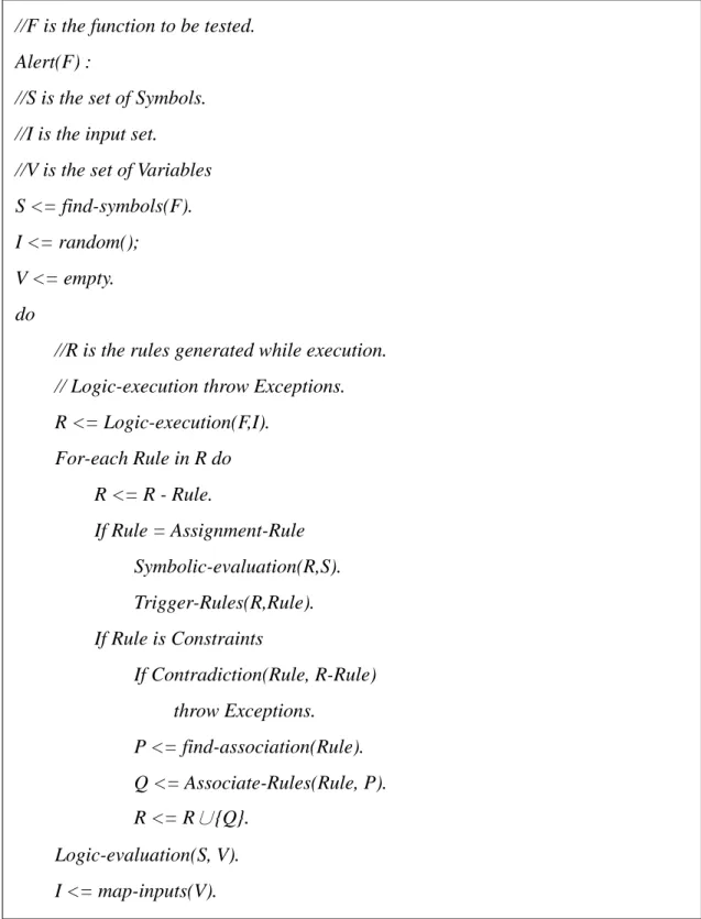
Figure 12, ALERT pseudo-code
Figure 12 is the algorithm of resolving inputs from symbols and constraints.
Conceptually, ALERT does the same things as DART and CUTE. That is to automate testing
process according to program execution, but we do trace the logic in the programs, not the
//F is the function to be tested. Alert(F) :
//S is the set of Symbols. //I is the input set. //V is the set of Variables S <= find-symbols(F). I <= random(); V <= empty. do
//R is the rules generated while execution. // Logic-execution throw Exceptions. R <= Logic-execution(F,I). For-each Rule in R do R <= R - Rule. If Rule = Assignment-Rule Symbolic-evaluation(R,S). Trigger-Rules(R,Rule). If Rule is Constraints If Contradiction(Rule, R-Rule) throw Exceptions. P <= find-association(Rule). Q <= Associate-Rules(Rule, P). R <= R∪{Q}. Logic-evaluation(S, V). I <= map-inputs(V).
actual values in the memory.
3.1. Instrumentation for Runtime Trace
We can't prove the existence of the transformation model from imperative language to
rule-based language. But we can model a program execution with rule-based language,
because in a program running instance, all variable dependencies have been decided. And also
alias naming can be resolved through a running instance interpretation. We never try to
transform an imperative language program to a rule-based program; instead, we try to model a
dynamic behavior of an imperative language program. In an imperative program, variables are
nodes spread entire program, static analysis try to find the links between the nodes during the
program execution, but we never ensure the links between variables would really happen.
There is a missing portal for a specified link. As a result, we can easily recognize that only
tracing in run-time, can we get the exactly linkage between variables, and guarantee
feasibility 'cause it is actually running.
3.2. Generation of Runtime Constraints
The information provided by a running program is totally different from the program
source code. In running program, all values are ‘active’, which affect each other in a
consequence. And such consequences provide us a clear obvious view of how programs run.
If we want to understand the control behavior of programs, an intuitive way is to locate every
control branches and print the concrete values during execution. It could take overhead to
and values is still unknown.
We propose another tracing mechanism that prints the whole branch constraints instead
of concrete values. Additionally, we modify the constraints to fit where the program controls
reach, that is, we insert the constraints exactly at the end of branch operation, no the
beginning. It makes a great reduce on the inspection overhead.
3.3. Symbolic Evaluation Framework
We use symbols to represent variables. If the value of some variable A transfers to
another variable B, we can modify the symbolic representation of variable B to A, and A is
still A. If after modification B, another operation modifies A to ‘A + 1’; then the
representations of both B and A become ‘A + 1’. Initially, we have symbols which represent
some variables, constraints that restrict the symbols to some fixed domain, and transaction
Figure 13, Flow chart of symbolic evaluation
We transfer an execution states into rule-based description. By substitutions between
variables and symbols, we found that we can illustrate the whole running path that is
composed by every single step of program executions by the accumulation of those steps. For
every execution step can be represented by symbolic compositions, we can evaluate the
symbols to reduce to the minimal constraints. Figure 13 shows how to replace symbols with
representations.
Briefly speaking, the basic concept of ALERT symbolic evaluation is mapping of
symbols. Initially, ALERT enforces every variable to map to itself. Every variable is unique
before the execution. After any modification expression, ALERT traces the original symbol of
the modified variable and combines old symbol with new obtained one. ALERT maintains
mapping, respectively. Once a symbol is modified to another symbol expression, ALERT
evaluates each symbol in the expression and looks up symbol maps for dynamic values. For
relative access, like pointer, ALERT uses composite symbols as a key to look up many-by-one
maps. In special cases, when some symbol operations require multiple relative accesses,
ALERT creates a dummy symbol during the evaluation of relative accesses. For example,
ALERT creates dummy symbols for ‘p’, ‘*p’ and ‘**p’ when dealing with ‘***p’ or creates
‘a’, ‘a []’, and ‘a [] []’ when dealing with ‘a[i] [j]’.
Symbolic evaluation terminates if the program reaches a halt state. The main purpose of
symbolic evaluation is to aggregate a multi-step program run to a single step. It makes
ALERT figure out the execution path in a logic way and obtain other execution paths by
inference on logic rules. After all symbols are resolved to their initial references, ALERT
sends them as inputs to next stage, logic evaluation.
3.4. Automatic Logic Evaluation
It may be impossible to model programs made by imperative language with logic rules,
but it seems to be possible to describe runtime behaviors in logic rules. Because the execution
of programs is unpredictable, we can’t reproduce the transaction of volatile program states.
But it is possible to reverse the behavior of an executed program. We try to solve the
following problem with logic: given rules describing a set of symbols or facts, and rules
contain constraints to restrict the binding of variables and symbols, we expect to unify
Figure 14, Flow chart of logic resolution
Previous section points out that the transformation from imperative language programs
to rule-based programs is possible if the volatile state is revertible. For this reason, we deploy
symbolic evaluation before logic evaluation. Symbolic evaluation performs dependency
forwarding on symbolic modification, which enables us to trace back the volatile state of
imperative language programs.
The main purpose of logic evaluation is to find a feasible input data according to given
symbolic constraints. Like figure 14, the evaluation process begins with empty logic variables
as input data, initially with bounded range constraints to specify valid domain. For each
symbolic constraint, we refine both right-hand-side and left-hand-side to minimal unit,
eliminate duplicated constraints, and annotate possible boundary to every logic variables. A
variable are triggered, when the boundary of some variable narrows down. It causes other
variables to get more precise boundaries. However, if the unification results are in conflict
with the constraints of some variables, the inference process restores the changed bindings
4. Implementation
This sector describes the design and architecture of ALERT. ALERT is composed of
three blocks: instrumenter, symbolic evaluator, and logic resolver. As Figure 15 shows, they
exchange messages through a top module, which is the UI and entry point of ALERT. ALERT
takes program source as input and executes the instrumented instance until error occurs or
ALERT is unable to generate inputs for a different path.
Figure 15, ALERT components
4.1. Instrumenter
The first contact with source code is the instrumenter. It takes program source as inputs
and generates testing interface and testing driver for runtime trace. The followings are design
4.1.1. Branch Oriented
The cut point is the program branch. Statically, program branches consist of two parts;
one is a conditional statement for checking, and another is some alternative paths to take. It
seems that we have two options: put our code before first part or put them after second part.
Both ways influence the same thing in source code. In the option one, the operation of
instrumentation includes not only the controlling log but also the evaluation of the condition
statement. It is called ‘cut point’. But in the option two, the operation is reduced to only
controlling log of the branch choices. It is a tradeoff between time and space. For performance
consideration, we insert many log operations in each branch choice instead of one log and
evaluation operation in the cut point.
4.1.2. Condition Sensitive
We break composite condition into independent ones. Because different combination of
these conditions leads to different program states even they are in the same basic blocks. With
the support of different program states, we can resolve the execution logic and generate
different path.
4.1.3. Function driven
The smallest unit of program is a function. Based on this, we can analyze each path in
the specified function. Each invocation of a function has its unique logic. Parameters of
invocation in the simplest way. With short tags labeling the parameters and local variables we
can distinguish variables under different scopes. And by aliasing all passed parameter and
return value, we can preserve the consistency of current program state while function
invocation.
4.2. Symbolic Evaluator
We discard the concrete values of program executions. We use the composted symbols to
explain how the program transfers information by variables. The following are design feature
of the symbolic evaluation.
4.2.1. Paired Symbols
ALERT requires two aspects of view of symbols to perform symbolic evaluation:
symbolic appearance and symbolic propagation. An appearance is what the symbol 'looks like'
Define an appearance A of some symbol x is that intuitively x is declared as A.
Ex:
int a; //a symbol whose symbolic appearance is ‘a’.
Define a propagation P of some symbol x is that the current state of x is
propagated from P. P can be composed by any symbol in any ways. Ex:
pi = 3.14159, r =10, area=r*r*pi;
box[0]=top(table), box[1]=top(box[1]), box[2]=near(box[0]);
Define a symbol domain S = {As, Ps} where As is a set of all symbolic
appearances, and Ps is a set of all symbolic propagations. The following
Define a replacement of an appearance A over a propagation X, denoted as Ra(A,
X), is that for every symbol C in A, if C equals X as propagation symbols, we substitute C with As[X].
Ex:
a=3, b=4, c=foo(b, c); foo(int x, int y){
return sqrt(x*x + y*y);
}//in function foo, Ra (As [foo.x,foo.y],[b,c]), As [foo.x]=As [a] and As [foo.y]=As [b]
Define a replacement of a propagation P over a appearance X, denoted as Rp(P,
X), is that for every symbol C in P, if C equals X as appearance symbols , we substitute C with Ps[X].
Ex:
pi = 3.14159, r =10, area=r*r*pi;
//after Rp (Ps [area], r),Ps [area]=10*10*Ps [pi]
Define a symbol replacement of an appearance symbol x over symbolic domain S,
denotes as Ra (S, x), said S’ = Ra (S, x) and S’ = { {a | a in Ps and x in Ps } , { Ra ( p, Ps
[x] | p in Ps } }.
Define a symbol replacement of a propagation symbol x over symbolic domain S,
denotes as Rp (S, x), said S’ = Rp (S, x) and S’ = { {a | a in As and x in As } , { Rp ( p, As
4.2.2. Dependency
The dependency relations between symbols are forwarding and rewriting. It is the
fundamental concept of symbolic evaluation. The forwarding is a replacement of the symbol
itself. The rewriting is a substitution of the symbol with another symbol.
Ex: x+=y; // after forwarding, P[x] is updated to P[x] + P[y]
fins=stdin; // rewriting the P[fins] as P[stdin]
4.3. Logic Resolver
These logic rules are implemented in SWI-prolog [16]. The followings are design feature
of logic resolver.
4.3.1. Variable
Logic variable is an empty container. It could bind to any possible values. The logic
variables describe an input of testing initially. And it will finally be assigned a feasible value
that satisfies the current constraints. The variables can be mapped to original parameters of
testing function. For some structures or array or pointer type, the variables can represent some
part of composed-type parameters, for example, a month field of a date structure, the 8th
element of an array of real numbers, or the 3rd offset of a pointer. ALERT generates the
4.3.2. Freezing Expression
Freezing expression is a set of expressions that associates some variables. The
expressions will limit value of the associated variable. For example, the freezing expression of
a positive odd value is like “freeze(X, [X > 0, X % 2 = 1])”. When the variable is bound, logic
engine evaluates its freezing expressions with the binding value. If the result is true, the whole
process proceeds and triggers other variable binding, otherwise the engine would trace back to
previous decision site and make alternative decision. The logic resolving routine terminates
successfully if all variables are bound and their freezing expressions are satisfied.
4.3.3. Domain Range
Domains are used to set the boundary of variables. For variables to have storage type and
specified storage bits, we can set up a signed integer X with 2 bytes length like “X
indomain(-32768..32767)”. For more advanced application, we can enumerate customized
types such as “Color indomain(red, blue, green)”, and it can be extended to display higher
order of abstraction of symbolic evaluation.
4.4. Implementation Difficulties
The main problems we encountered during ALERT implementation are to generate
testing interface and eliminate program state-transaction into stateless logic rules. The former
problem appears in the instrument stage. There are usually various user-defined types
different user-defined type automatically, we maintain a stack for registration of structural
data-types, a vector for pointers and a list for array type.
The later problem comes from symbolic evaluating stage. It is the key idea for logic
evaluating. Because logic engine doesn’t care the order of rules, but program logic does, we
make some modification on symbol variables to fix the transaction. We ensure that through
symbolic evaluating ALERT can preserve the states and reversibility of program logic.
4.4.1. Generation of User-defined Type Interface
To generate testing interface for automatic execution, we have to create fixed functions
that dedicates to input parameters of user specified types. In the beginning, we try to examine
the length of specified type and flip the bits to initialize. It can reflect the resolved values, but
without field information. The field information tells about the number of sub-elements and
their types. It became a problem that we can’t catch the length of sub-elements during bits
flipping. We build a type sub-system to get rid of it, according to [9]. We base on fundamental
types and construct composed type with point, array, or structure. The inputs function for
testing interface and driver can be rendered with recursive type inheritance.
4.4.2. State-sensitive Variable Renaming
In the beginning, we thought that the renaming of variables is simple. It is easy to
imagine that as it comes to a state modification, we just store in data pool and change the
decide which the same symbol variable is. A symbol variable could have different names
when it is transferred to another scope. The solution is to exchange the appearance of all
symbols dynamically during identical symbol selection to prevent symbol variable confusing.
5. Experimental Results
We evaluate our work with zlib [17], a well-known compressing library. We apply
ALERT on zlib and perform coverage evaluation by conjunction of gcc and gcov [1]. Gcov is
a coverage analysis tool that provides coverage statistics include how often each line of code
executes, what lines of code are actually executed, and how much computing time each
section of code uses.
5.1. Instrumentation and Generation Overhead
The space overhead of ALERT instrumentation is one line-of-code for a significant
branch. We insert one line of log trace code into the beginning of a branch block. This results
in that our space overhead is in proportion to the conditional statements in programs. The
execution overhead of instrumentation is an additional record operation for each conditional
evaluating, so one running instance may have extra operations in proportion to the condition
statements along the paths.
The testing cases generation overhead is one logic variable for an effective function
parameter, but if parameters contain sub-field, logic engine may require more than one logic
variable to resolve symbols. We generate one logic script for the next running instance, so the
total testing script generation of ALERT application is as many as the found possible paths.
5.2. Expand and Explore
discovery. The discovery algorithm records constraints of previous running instance in
database and produces constraints that differ from those in database by negating some of the
constraints. In the running instance, the program itself may reach new branch that was not
visited before in previous instance. The trace log may contain new constraint entry for
negation. ALERT expand the program branches and explore the newly expended node at the
same time.
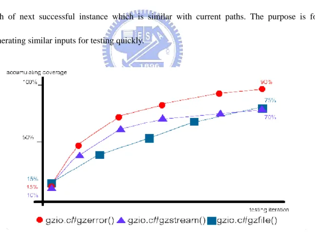
5.3. Similar Path Discovery
The ALERT path discovery algorithm firstly negates the last constraints, resulting in the
path of next successful instance which is similar with current paths. The purpose is for
generating similar inputs for testing quickly.
Figure 16, Coverage analysis
displays the coverage percentage of running iterations accumulatively. The y axis displays the
count of successful generated inputs against a program. Initially, the inputs for first running
instance are zero, so the coverage percentage is about 10% ~ 15%. It could tell that empty
input path contains 15% of LOC. At the end of testing, all program’s coverage accumulated
about 70% ~ 90%. It is because some conditional ALERT couldn’t resolve. Some of them
may be pointer arithmetic or array element cross reference. We can deal with pointer
arithmetic in symbolic evaluation, by constructing a nameless symbol to represent calculated
pointer. But the logic engine can’t take any variable without a name to reference, so does
array reference. It also a limitation of ALERT, that it can’t work in functions take all
parameter as pointer or array. This would leave the room for our future improvement
6. Conclusion
Testing is a time consuming process and hard to automate. Its main purpose is to make
sure every functionality works. The simplest suggestion is to “show it wrong or right”. If we
do the testing manually, we could lose in the labyrinthine program execution states. To
automate the testing processes, it is essentially important to direct the testing program. We
divide ALERT into three stages: instrumenter, symbolic evaluator, and logic resolver. Each
stage will generate inputs for next stage. A control top module exchanges messages between
every stage. It is a better architecture for testing duty.
Program states consist of thousands of variables and their combinations are
unpredictable. We know it is impossible to enumerate program states through the values of
variables. So we try an alternative way to enumerate program logic. It is much feasible that a
program behavioral representation can be considered as the combination of its logic
constraints. There are many related work that take advantage of program logic. ALERT is the
first application for dynamic analysis.
We discover that program logic is reversible under some circumstances. The reversible
states enable ALERT to solve constraints and produce feasible inputs that lead program to
perform a different execution path. By recording constraints of each running instance, we can
enforce the program to perform all of its possible paths.
ALERT is just a beginning. For the different testing strategy, such as integration testing,
we can enhance ALERT in the component interaction aspect, which enable ALERT to resolve
more complicated program logic. In addition to simulating the manual input operation,
ALERT could be extended to generate specified environments for exhibitions of security
issues by modification of the messages transmitting between the logic resolver and symbolic
evaluator layers.
6.1.1. Feasible Input Generation
We desire a tool that tells when and how a defect or fault could occur, especially when
we don’t have enough information to prove the existence of the feature. ALERT is just a
beginning of that. It automatically resolves specified program logic (or called constraint rules)
and produces feasible inputs to render program in the way we want. Not only single function,
but integration constrains can be evaluated as a collection of symbols. We look forward to a
way of understanding the program semantics automatically. This method would become a
new trend in the field of automatic testing to deal with every logic feature in program.
6.1.2. Delta Debugging
In the former software debugging process, we are familiar with getting in the reference
between source codes and runtime interaction. To find out what is going wrong behind
programs, it would be convenient for programmers to automate the process that traces
programs without manual assistance. Delta debugging[2] is a latest debugging method that
debugging requires the comparison of a failure program run with a successful one. Moreover,
the failing program execution characteristics do not actually differ much from the successful
program execution. Delta debugging eliminates the common characteristics through
comparison of value transaction and cause chain of two runs. Nevertheless, in real cases, we
only have program failing runs. That is a tough work to determine the similarity of failing run
and successful runs with which we can apply Delta debugging method.
References
[1] "gcov: a Test Coverage Program http://gcc.gnu.org/onlinedocs/gcc-3.0/gcc_8.html,"
[2] H. Cleve and A. Zeller, "Locating causes of program failures," in ICSE '05: Proceedings
of the 27th International Conference on Software Engineering, 2005, pp. 342-351.
[3] W. R. Bush, J. D. Pincus and D. J. Sielaff, "A static analyzer for finding dynamic
programming errors," SPE, vol. 30, pp. 775-802, 2000.
[4] J. Whaley, M. C. Martin and M. S. Lam, "Automatic extraction of object-oriented
component interfaces," in ISSTA '02: Proceedings of the 2002 ACM SIGSOFT International
Symposium on Software Testing and Analysis, 2002, pp. 218-228.
[5] D. Jackson, "Aspect: detecting bugs with abstract dependences," ACM Trans. Softw. Eng.
Methodol., vol. 4, pp. 109-145, 1995.
[6] D. Engler, D. Y. Chen, S. Hallem, A. Chou and B. Chelf, "Bugs as deviant behavior: A
general approach to inferring errors in systems code," in SOSP '01: Proceedings of the
[7] S. Hallem, B. Chelf, Y. Xie and D. Engler, "A system and language for building
system-specific, static analyses," in PLDI '02: Proceedings of the ACM SIGPLAN 2002
Conference on Programming Language Design and Implementation, 2002, pp. 69-82.
[8] H. R. and J. B., "Purify: Fast Detection of. Memory Leaks and Access Errors." Winter
USENIX. Conference, 1992.
[9] P. Godefroid, N. Klarlund and K. Sen, "DART: Directed automated random testing," in
PLDI '05: Proceedings of the 2005 ACM SIGPLAN Conference on Programming Language Design and Implementation, 2005, pp. 213-223.
[10] B. Demsky and M. Rinard, "Data structure repair using goal-directed reasoning," in ICSE
'05: Proceedings of the 27th International Conference on Software Engineering, 2005, pp.
176-185.
[11] H. Agrawal and E. H. Spafford, "Bibliography on debugging and backtracking,"
SIGSOFT Softw. Eng. Notes, vol. 14, pp. 49-56, 1989.
[12] T. Wang and A. Roychoudhury, "Automated path generation for software fault
localization," in ASE '05: Proceedings of the 20th IEEE/ACM International Conference on
Automated Software Engineering, 2005, pp. 347-351.
[13] C. Flanagan, K. R. M. Leino, M. Lillibridge, G. Nelson, J. B. Saxe and R. Stata,
"Extended static checking for java," in PLDI '02: Proceedings of the ACM SIGPLAN 2002
Conference on Programming Language Design and Implementation, 2002, pp. 234-245.
[14] lp_solve http://lpsolve.sourceforge.net/
[15] K. Sen, D. Marinov and G. Agha, "CUTE: A concolic unit testing engine for C," in
ESEC/FSE-13: Proceedings of the 10th European Software Engineering Conference Held Jointly with 13th ACM SIGSOFT International Symposium on Foundations of Software Engineering, 2005, pp. 263-272.
[16] SWI-Prolog -- an LGPL comprehensive portable Prolog compiler. http://www.swi-prolog.org/
[17] zlib -- A Massively Spiffy Yet Delicately Unobtrusive Compression Library.