Linewidth reduction and wavelength tuning
of an erbium-doped fiber laser by use of a
single-mode-selected and side-mode-suppressed
Fabry–Perot laser diode
Gong-Ru Lin and Jung-Rung Wu
A single-mode and highly side-mode-suppressed 1.55-m Fabry–Perot laser diode 共FPLD兲 is achieved by feedback injection with an erbium-doped fiber laser共EDFL兲. For selection of the strongest longitudinal mode from the gain spectrum of the FPLD for lasing in the EDFL, the FPLD is operated at just below the threshold condition and is feedback injected by 0.02% of the EDFL output power. The lasing mode and center wavelength of the proposed single-mode FPLD source are decided by cross-correlated gain profiles of the EDFL and the FPLD; however, the effect of FPLD injection modes is found to be more pronounced. The optimized lasing linewidth共system limitation兲 and side-mode suppression ratio of 0.01 nm and ⬎49 dB are obtained, which are far better than those of a FPLD at free-running condition. The worst linewidths at 3- and 10-dB decay are observed to be at approximately 0.016 and 0.05 nm, respectively. Linear wavelength tuning of as much as 4.5 nm共from 1558.7 to 1563.2 nm兲 by adjustment of the temperature of the FPLD from 10 °C to 40 °C at just below threshold is reported. The wavelength-tuning slope is approximately 0.14 nm兾°C under temperature accuracy of 0.1 °C. © 2003 Optical Society of America
OCIS codes: 060.2320, 140.2020, 140.3600.
1. Introduction
Highly stable continuous-wave lasers with narrow spectral linewidth and low-noise performance at fixed wavelengths are the promising optical transmitters or testing sources in traditional fiber-optic com-munication systems. With the fast evolution of erbium-doped fiber amplifiers共EDFAs兲, the narrow-linewidth and wavelength-tunable operation of such a high-power optical source with a wide gain spec-trum has become an intriguing research topic. Pre-viously, versatile state-of-the-art optical filters such as direct-write or external fiber Bragg gratings,1
tun-able fiber Fabry–Perot etalons,2and other diffraction
gratings with extremely narrow linewidth have suc-cessfully emerged to meet these demands.
How-ever, these achievements are either complicated in fabrication or less cost effective. Recently novel external-feedback- or self-seeding-based filtering techniques for diode-laser sources have also been demonstrated.3 Up to now, numerous researchers
have been interested in building up narrow-linewidth and wavelength-tunable er-doped fiber lasers 共ED-FLs兲 for such uses as characterizations of passive fiber-optic devices and submodules, owing to their striking features such as a broadband spontaneous emission property, high output power, and direct fi-ber compatibility. The most common and simple im-plementation to build up a narrow-linewidth EDFL source is by addition of a commercially available, intracavity optical bandpass filter. Although this approach exhibits the important merit of wavelength-tuning simplicity, its side-mode-suppressed ratio 共SMSR兲 and filtered linewidth are still poor.
More recently researchers have reported a distin-guished and cost-effective method for generating wavelength-tunable single-mode laser pulses from a Fabry–Perot laser diode 共FPLD兲 by self-seeding it with low-level 共approximately 0.2%–6%兲 feedback power. Nearly single-mode pulses with a SMSR of
The authors are with the Institute of Electro-Optical Engineer-ing, National Chiao Tung University, No. 1001, Ta Hsueh Road, Chinchu 300, Taiwan. The e-mail address of G.-R. Lin is [email protected].
Received 19 December 2002; revised manuscript received 24 April 2003.
0003-6935兾03兾275477-06$15.00兾0 © 2003 Optical Society of America
higher than 40 dB over a tuning range of 11.5 nm4
were generated from the self-seeding FPLD. None-theless, this technique still relies on the use of a tunable linearly chirped fiber Bragg grating to provide wavelength-selective feedback and output fil-tering functions. Alternatively, the fast and wide-range wavelength tuning of the FPLD can be implemented via the provision of optical feedback to a self-seeded laser diode that also acts an active Fabry–Perot filter. Wavelength selection is realized by one’s electrically tuning the comblike spectral re-sponse of such an ordinary FPLD biased below its threshold, a stepwise wavelength tuning over a range of 9 –11 nm with a SMSR from 13 to 22 dB throughout the range.5–7 In particular, the power penalty
re-sulting during the self-seeding-induced mode-selecting process is another disadvantage.
2. Experiment
To resolve the predicament of the power dissipation and the finite SMSR performance of the self-seeded FPLD-based filtering technique, we demonstrate a new approach for generating a high-power, single-mode, and ultrahigh SMSR FPLD by using a free-running EDFL and feedback-injecting techniques in this paper. The EDFL is formed by the self-feedback of a commercial EDFA with optical cou-plers. The narrow-linewidth operation is achieved via the controlled optical feedback injection from the EDFL to the FPLD without the use of any optical circulator, fiber Bragg grating, and optical bandpass filter. The proposed system further benefits from advantages including a simplified setup and high out-put power as compared with conventional appara-tuses. The effects of the FPLD current and temperature and the EDFL feedback power on the SMSR of the EDFL–FPLD output are discussed.
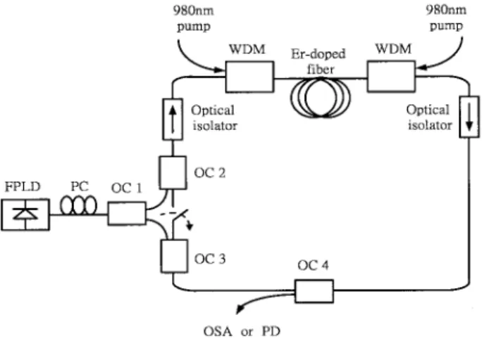
The original configuration of the EDFL-feedback-injected FPLD is illustrated in Fig. 1. A bidirection-ally pumped commercial EDFA module with a maximum output of 23 dBm is a closed loop and is
feedback injected with a commercial fiber-pigtailed FPLD; they are connected to each other by use of optical couplers with predetermined power-splitting ratios and an in-line polarization controller 共PC兲. Such a design excludes the use of other expansive components such as optical circulators, fiber Bragg gratings, distributed Bragg reflectors or distributed feedback laser diodes, and narrow band-pass filters. The wavelength, threshold current, and longitudinal mode spacing of the free-running FPLD at 35 °C are approximately 1560 nm, 12 mA, and 1.2 nm, respec-tively. In experiments, optical coupler 1共OC1兲 共90兾 10兲 couples the output of the FPLD into the EDFL with OC2 共50兾50兲 and feeds back the EDFL output into the FPLD with OC3共90兾10兲. The optical output of the EDFL is coupled by OC4共65兾35兲, which is also preserving the gain saturation in the fiber ring. The PC between the FPLD and OC1 is carefully adjusted to control the polarization of the light feedback into the FPLD because it is important to align the states of polarization with one of the eigenstates of polar-ization of the FPLD and the EDFL. This arrange-ment guarantees single-mode oscillation, optimizes the SMSR, and suppresses the laser noise concur-rently. The 35%-FPLD-filtered EDFL output is monitored by an optical spectrum analyzer with 0.01-nm resolution共Advantest, Q8384兲 and an optical powermeter共ILX Lightwave, OMM-6810B兲. The in-line PC is employed to fine tune the feedback-injection power from the EDFL to the FPLD. The FPLD is then controlled at just below the threshold condition with the EDFL-feedback-injected power ad-justed at between 0.01% and 0.05% of EDFL power. The feedback from the EDFL and the cavity loss of the FPLD facilitate in selection of one longitudinal mode with improved SMSR lasing in the FPLD, which then is feedback injected to EDFL to obtain a linewidth-reduced output. Under the precise con-trol on the feedback power of approximately 12.4W, the optimized linewidth-reduction performance is ob-served while the other side modes in either the FPLD or the EDFL are greatly suppressed during the gain competition process.
3. Results and Discussions
A. Spectral Analysis
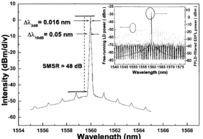
One obtains the best narrow-linewidth operation of the EDFL and FPLD’s link by driving the FPLD at just below threshold, as shown in Fig. 2. As the partial output of the EDFL feedback injects into the FPLD, the FPLD-filtered EDFL’s lasing spectrum with a SMSR of ⬎48 dB is observed, and the mea-sured spectral linewidths are 0.016 and 0.05 nm at 3-and 10-dB decay, respectively. As observed in our experiment, the measured SMSR is enhanced by nearly 10 dB as the wavelength resolution of the optical spectrum analyzer is improved from 0.1 to 0.01 nm. The higher wavelength resolution results in an averaging over a smaller resolution band to obtain the peak signal, which not only shrinks the measured spectral line but also improves the SMSR
Fig. 1. Experimental setup of the narrow-linewidth FPLD-filtered EDFL. PC, polarization controller; OC, optical coupler; PD, photodetector; OSA, optical spectrum analyzer; WDM, wave-length division multiplexing coupler.
level 共as well as accuracy兲. Note that the typical longitudinal mode linewidth of the FPLD at a free-running scheme is still large as compared with that of the FPLD-filtered EDFL 共see the inset of Fig. 2兲. One can clearly observe that the lasing peak of the FPLD-filtered EDFL matches well with the peak mode in the free-running FPLD spectrum. Because the filtering ability of the FPLD to the EDFL is less decisive when operated at below or well above the threshold condition, the EDFL is thus lasing at self-seeding or multi-FPLD modes. In contrast, the EDFL acts rather like a closed-loop amplifier 共or slave laser兲 for the FPLD in the latter case. The FPLD becomes nearly transparent as it is biased close to the threshold current. This leads to the am-plification of a broadband spontaneous-emission-limited spectrum of the FPLD in the EDFL ring cavity. After several round trips, one of the ampli-fied longitudinal modes within the correlated gain profiles of the EDFL and the FPLD eventually over-comes the loss of the intracavity FPLD operated at the just-below-threshold condition, which then dom-inates the lasing wavelength of the FPLD as well as the EDFL. Although the use of a circulator instead of three couplers can achieve a comparable SMSR, it cannot make EDFA lase because the feedback of the EDFA is directly injected into the FPLD cavity but not to the EDFA itself. This eventually results in a broadened lasing spectrum, as shown in Fig. 3. The feedback injection of the EDFA to both the FPLD and the EDFA itself is mandatory to the linewidth-reduction effect of the proposed system. The coupler-based system thus facilitates the lasing of the EDFA and the reduction of its spectral linewidth feedback into the FPLD, which helps in reducing the cross-correlated gain profile of the FPLD and lasing the FPLD at a narrower linewidth. In comparison with the circulator-based system, the use of couplers further benefits from the flexibility of tuning the feedback-injection ratio to the FPLD and the EDFL. Moreover, the circulating function can also be simu-lated by the coupler scheme when the connection
be-tween OC2 and OC3 is opened共the feedback from the FPLD through OC3 to the EDFL is interrupted by the optical isolator兲. The reduction in the number of the lasing modes of the external cavity relies strictly on shortening the external cavity length; for example, a linear cavity EDFL might be one of the potential candidates to meet this demand. However, the shortened cavity inevitably increases the mode spac-ing and the mode linewidth in the meantime. An alternative way is to use a distributed feedback laser diode instead of a FPLD as the active filter, which, however, is less cost effective.
B. Power Stability and Wavelength Tunability
The power-current characteristics of the free-running FPLD operated at 35 °C, the free-running EDFA’s output power, and the EDFL with an intracavity feedback-injection-controlled FPLD that functions as an intracavity optical bandpass filter are shown in Fig. 4. It can be seen that the FPLD-filtered EDFL has already been lasing with output power of 60 mW even though the FPLD is unbiased. In comparison,
Fig. 2. EDFL with the feedback-injection FPLD, and the output spectra of the free-running FPLD and the FPLD-filtered EDFL biased at below the threshold current and operated at 35 °C. div, division.
Fig. 3. Comparison of lasing spectra by use of optical circulator-and coupler-based schemes.
Fig. 4. P–I curves of the outpower of the free-running FPLD, the free-running EDFA, and the FPLD-filtered. EDFL operated at 35 °C.
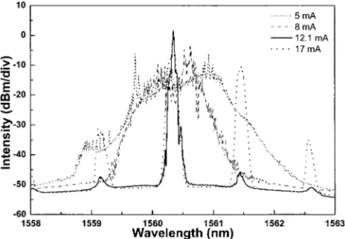
the output power of the FPLD-filtered EDFL is as much as 46.5 mW, which corresponds to an insertion loss of 1.1 dB. It is found that the power stability of the EDFL is superior, which exhibits very low fluc-tuation共of approximately 1%兲 even though the driven current of the FPLD changes. The residual varia-tion is mainly attributed to the slightly red-shifted gain peak of the FPLD and the less-flattened EDFA gain profile. The varied spectra of the EDFL, con-trolled by the intracavity feedback-injected FPLD driven at different current conditions 共below, near, and above the threshold current兲 and a constant op-erating temperature共35 °C兲, are illustrated in Fig. 5. It is found that the output spectrum is slightly broad-ened and the SMSR is greatly degraded owing to the amplification of the side modes when the FPLD is driven at higher currents above threshold. The mode numbers of the EDFL ring cavity also abruptly increases as the bias current of the FPLD increases. These results can clearly be interpreted to mean that the peak wavelength among these modes is still pre-dominated by the cross-correlated gain profiles of the EDFL and the FPLD5; however, the effect of the
FPLD is more pronounced. One striking feature of our proposed scheme is for one to operate the EDFL at single FPLD mode with a high SMSR regime by driving the feedback-injected FPLD at near-threshold current. When the FPLD is operated at a nearly lasing regime, the broadband spectrum of the FPLD reveals that there is still a competition be-tween cavity modes resulting from spontaneous emis-sions. At this stage, even a small intracavity feedback power can efficiently lead to a single mode that can be sustained in the cavity, which eventually suppresses the other lasing modes of the EDFL.7
Mode selection is therefore achieved by one’s fine tuning the power and polarization of the feedback light from the EDFL cavity. The drift in the peak wavelength of the principle lasing mode in the FPLD-filtered EDFL under an increasing FPLD current is negligible in that the EDFL and the FPLD are injec-tion locked to each other. The SMSR of the
FPLD-filtered EDFL spectrum can still be maintained at 40 dB or greater at the driven current of the FPLD, ranging from 9.5 to 12 mA, as shown in Fig. 6. The narrow-linewidth generation can be achieved only when the FPLD is driven at below-threshold current within a 20% deviation, whereas the other side mode arises when the current of the FPLD exceeds the threshold current. It is found that such a high SMSR decreases dramatically as the FPLD’s driven current becomes equivalent to or slightly higher than the threshold value.
The temporal stability of the peak wavelength and the output power of the FPLD-filtered EDFL is shown in Fig. 7. It is found that the variation in the peak wavelength is⫾0.05 nm. The peak wave-length of the system is highly stable without me-chanical or environmental disturbance. The short-term power stability of the EDFL output has been monitored. The maximum fluctuation of the 60% coupling output power共27.2 mW兲 is 0.03 mW or ⌬P兾P ⫽ 1.18 ⫻ 10⫺3with a measuring speed of 100
Hz. If we further use a high-speed detector and a digital multimeter共New Focus, 1014, and Hewlett
Fig. 5. Measured spectra of the EDFL with the feedback-injection FPLD biased at different current conditions.
Fig. 6. Evolution of the SMSR of the FPLD-filtered EDFL at different FPLD currents.
Fig. 7. Stability in peak wavelength of the FPLD-filtered EDFL and the long-term FPLD-filtered EDFL output power.
Packard, HP34401A兲 with a data-acquisition speed of 1 ms, the measured power fluctuation is only 4.4⫻ 10⫺3. The long-term drift in output power of the FPLD-filtered EDFL measured from OC4共35%兲 is below 0.2% within 2.5 h. These results can clearly be interpreted to mean that the proposed FPLD-filtered EDFL system could probably exhibit a narrow linewidth, actually, a single-FPLD-mode lasing spectrum, which is already beyond the sys-tematic resolution. On the other hand, although a maximum SMSR of greater than 50 dB in transient 共⬃10 min兲 is obtained, a slightly decayed but rela-tively stable SMSR of 49 dB at a measuring dura-tion of 1 h or longer is preferred. Experimental results also reveal that the increase in the driven current 共or decrease in operating temperature兲 of the FPLD may not only lead to the growth of other FPLD modes and the broadening of the spectral linewidth but also cause a red shift in the lasing spectrum. At last, the temperature-dependent wavelength output of the FPLD and the output power stability of the FPLD-filtered EDFL at dif-ferent temperatures are shown in Fig. 8. One may
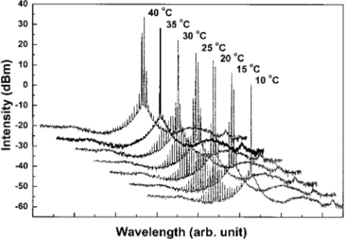
obtain the linear wavelength tuning by simply changing the FPLD temperature from 10 °C to 40 °C but maintaining its bias current at just below threshold 共from 16 to 20 mA兲. Under this condi-tion, the output wavelength of the FPLD-filtered EDFL linearly increases from 1558.7 to 1563.2 nm. This corresponds to a wavelength-tuning sensitiv-ity of approximately 0.14 nm兾°C. Although the SMSR of the EDFL output at different FPLD tem-peratures is unavailable to keep as a constant, the best SMSR of the regenerative EDFA with a FPLD filter operated at 40 °C can still be as high as 24 dB. Figure 9 illustrated the output measured of the FPLD-filtered EDFL at temperatures from 10 °C to 40 °C at 5 °C increments. The modes of the FPLD are found to red shift while the temperature of the FPLD increases. As the temperature decreases from 40 °C to 10 °C, the FPLD changes from spon-taneous emitting to lasing mode under the constant driven current of the FPLD, which leads to a breakup of the injection locking between the FPLD and the EDFL. The degraded lasing spectra at different temperatures that are individually con-tributed by the EDFL and FPLD can be observed. Nonetheless, we have also observed that the FPLD’s filtering capability can be recovered, and lasing at a desired wavelength共with tiny deviation兲 occurs via fine tuning of the FPLD’s driven current to below threshold at certain temperatures. The SMSR of the FPLD-filtered EDFL at different FPLD temperatures have been measured and shown in Fig. 10. As the FPLD is controlled at a temperature far from room temperature, the output spectrum with decreasing SMSR is observed. This is mainly attributed to the instability of the temperature-controlled performance of the FPLD at lower- and higher-temperature regions. The FPLD has been shown to exhibit a distinguished contribution to the linewidth reduction and side-mode suppression of the EDFL, at a cost, however, of a nearly 20% additional cavity loss.
Fig. 8. Temperature-dependent wavelength output of the FPLD-controlled EDFL and output power stability from 10 °C to 40 °C.
Fig. 9. Output spectra of the FPLD-filtered EDFL biased from 10 °C to 40 °C.
Fig. 10. SMSR of the FPLD-filtered EDFL at different FPLD temperatures.
4. Conclusions
In conclusion, we demonstrate a novel approach for obtaining narrow-linewidth or single-FPLD-mode lasing in the EDFL with a high SMSR by adding a FPLD into the EDFL cavity共connected by commer-cial optical couplers兲 and feedback injecting the FPLD with part of the EDFL output via a polariza-tion controller. For selection of the strongest mode from the gain spectrum of the FPLD for lasing in the EDFL ring cavity, the FPLD biased at just below the threshold condition with an operating temperature of 35 °C also functions as an active optical bandpass filter. The lasing wavelength is controlled by gain profiles of both the EDFL and the FPLD; however, the effect of FPLD injection modes is found to be more pronounced. Such a scheme successfully links the high-gain amplification characteristics of a typical EDFL ring cavity and the mode-selecting and the wavelength-tuning capabilities of the FPLD. With this technique, the narrowest 3- and 10-dB spectral widths and the highest SMSR are 0.016 nm, 0.05 nm, and ⬎49 dB, respectively. Such a FPLD-filtered EDFL provides average output power as great as 46.5 mW. The fluctuation in the peak wavelength and the output power are less than 0.2 nm and within 0.2%, respectively. The value of the SMSR abruptly decreases as the driven current of the FPLD in-creases beyond threshold. Linear wavelength tun-ing of ⬎4.5 nm 共from 1558.7 to 1563.2 nm兲 by adjustment of the temperature of the FPLD from 10 °C to 40 °C at just below threshold is reported. The wavelength-tuning performance of the FPLD-injected linewidth-reduced EDFL system imple-mented by control of the temperature of the FPLD with an accuracy to 0.1 °C is also reported. Such a
system essentially benefits from advantages such as simple design, compactness, and cost effectiveness as compared with the conventional single-mode and wavelength-tunable lasers.
This paper was supported in part by National Sci-ence Council, Taiwan, grant NSC91-2215-E-009-039.
References
1. G. A. Ball, W. W. Morey, and W. H. Glenn, “Standing-wave monomode erbium fiber laser,” IEEE Photon. Technol. Lett. 3, 613– 615共1991兲.
2. J. L. Zyskind, J. W. Sulhoff, J. Stone, D. J. Digiovanni, L. W. Stulz, H. M. Presby, A. Piccirilli, and P. E. Pramayon, “Electri-cally tunable, diode-pumped erbium-doped fibre ring laser with fibre Fabry–Perot etalon,” Electron. Lett. 27, 1950 –1951共1991兲. 3. N. Park, J. W. Dawson, and K. J. Vahala, “All fiber, low thresh-old, widely tunable single-frequency, erbium-doped fiber ring laser with a tandem fiber Fabry–Perot filter,” Appl. Phys. Lett.
59, 2369 –2371共1991兲.
4. S. Li, K. S. Chiang, W. A. Gambling, Y. Liu, L. Zhang, and I. Bennion, “Self-seeding of Fabry–Perot laser diode for generat-ing wavelength-tunable chirp-compensated sgenerat-ingle-mode pulses with high-sidemode suppression ratio,” IEEE Photon. Technol. Lett. 12, 1441–1443共2000兲.
5. S. Li, K. S. Chiang, and W. A. Gambling, “Fast wavelength tuning of a self-seeded Fabry–Perot laser diode with a Fabry– Perot semiconductor filter,” IEEE Photon. Technol. Lett. 13, 1364 –1366共2001兲.
6. Y. Zhao and C. Shu, “Single-mode operation characteristics of a self-injection seeded Fabry–Perot laser diode with distributed feedback from a fiber grating,” IEEE Photon. Technol. Lett. 9, 1436 –1438共1997兲.
7. M. Schell, D. Huhse, A. G. Weber, G. Fischbeek, D. Bimberg, D. S. Tarasov, A. V. Gorbachov, and D. Z. Grabuzov, “20 nm wavelength tunable single mode picosecond pulse generation at 1.3m by self-seeded gain-switched semiconductor laser,” Elec-tron. Lett. 28, 2154 –2155共1992兲.