國
立
交
通
大
學
電信工程學系
碩 士 論 文
IEEE 802.16 無線系統上行鏈路之以
基因演算法與用戶分組資源分配
Resource Allocation with Genetic Algorithm and SS
Grouping for Uplinks in IEEE 802.16 Systems
研 究 生:邱 胤
指導教授:張仲儒 博士
IEEE 802.16 無線系統上行鏈路之以
基因演算法與用戶分組資源分配
Resource Allocation with Genetic Algorithm and SS
Grouping for Uplinks in IEEE 802.16 Systems
研 究 生:邱胤 Student:Yin Chiu
指導教授:張仲儒 博士 Advisor:Dr. Chung-Ju Chang
國 立 交 通 大 學
電 信 工 程 學 系
碩 士 論 文
A Thesis
Submitted to Department of Communication Engineering
College of Electrical and Computer Engineering
National Chiao Tung University
in partial Fulfillment of the Requirements
for the Degree of Master of Science
in
Communication Engineering
June 2008
Hsinchu, Taiwan
IEEE 802.16 無線系統上行鏈路之以
基因演算法與用戶分組資源分配
研究生:邱胤 指導教授:張仲儒 博士Mandarin Abstract
國立交通大學電信工程學系碩士班
摘
要
隨著無線系統傳輸在現今通訊系統的重要性日益增加,要提供多媒體傳輸 服務品質保證(quality of service, QoS)成為一個很重要的議題。為了達到最 佳的系統資源利用並提供服務品質保證,我們在 IEEE802.16 虛擬多發多收 (virtual multiple-input-multiple-output (MIMO))上行鏈路系統提出了一個 採用基因演算法暨用戶分組的資源分配(resource allocation with genetic algorithm and SS grouping, GGRA)機制。在機制中使用基因演算法來決定排程 順序,並設計了速率分配策略(rate assignment strategy)來動態調整各種服務 的優先次序及分配資源大小。我們提出的 GGRA 機制會在考慮系統限制條件如能 量、接收天線數等限制下,找到最佳的排程結果,來使得系統傳輸速率最大化, 並滿足各種服務的品質保證。在計算時間上,本方法也能利用平行處理的方式達 到足夠快的處理速度,因此 GGRA 可應用於實際系統中,成為一個有效並可以實 現的排程機制。
Resource Allocation with Genetic Algorithm and SS
Grouping for Uplinks in IEEE 802.16 Systems
Student:Yin Chiu Advisor:Dr. Chung-Ju Chang
English Abstract
Department of Communication Engineering
National Chiao Tung University
Abstract
In this thesis, a resource allocation with genetic algorithm and SS grouping (GGRA) scheme is proposed for IEEE 802.16 uplink communication systems. The GGRA scheme designs a rate assignment strategy applied with a predefined residual lifetime to dynamically allocate resource to each service type. It also aggregates high correlation subscriber stations (SSs) into the same group to avoid mutual user interference and adopts genetic algorithm to find an optimal assignment vector. It can maximize the system throughput while satisfying the QoS requirements. Simulation results show that the proposed GGRA scheme has better performance than the EFS algorithm and the MLWDF algorithm in system throughput, voice/video packet dropping rate, unsatisfied ratio of HTTP users/packets, and FTP throughput. It can also be found that the GGRA scheme has a feasible computation complexity so that it is feasible in real applications.
Acknowledgement
誌 謝
本篇論文的完成,首先要感謝指導教授張仲儒教授在學術論文上的悉心指 導,以及在處事及人生規劃上的諄諄教誨,讓我在兩年的研究生活中找到自己未 來努力的目標。也要感謝不辭辛勞犧牲下班休息時間來與我們討論及指導論文的 芳慶學長以及在無線通訊領域鑽研多年的志明學長及耀興學長,給了我許多寶貴 的建議,也解答了我的疑惑。在實驗室的生活中陪伴我的文祥、詠翰和振宇學長, 也感謝你們在生活及課業上曾給予我的諸多協助。兩年的碩士班研究生涯轉瞬即 逝,但其中許多的歡笑與淚水也總是讓我想起仍十分感動而快樂。進實驗室時熱 情歡迎我們的學長姐建安、建興、正昕、世宏、佳泓、佳璇,研究生涯中甘苦與 共一起努力的浩翔、英奇、維謙、宗利、巧瑩,還有努力帶給我們實驗室歡樂時 光的學弟妹志遠、欣毅、和儁、盈伃,以及辛苦的助理惟媜和玉棋。因為有大家 的陪伴,在課業上一起研究討論,課餘也一起出遊、吃飯、打球、唱歌度過許多 歡樂的時光,讓辛苦的研究生活十分充實也增添了許多活力和回憶。很開心當初 選擇加入寬頻網路實驗室這個大家庭,也祝福實驗室的大家學業順利,畢業後一 帆風順! 最後,謹以此篇論文獻給我最摯愛的父母和妹妹,以及所有一直關心、支 持我的親友們。 邱胤 謹誌 2008 年 7 月Contents
Mandarin Abstract...i
English Abstract ...ii
Acknowledgement ... iii
Contents ...iv
List of Figures...v
List of Tables...vi
Chapter 1 Introduction...1
Chapter 2 System Model ...6
2.1 OFDMA System Architecture...6
2.2 OFDMA System with Virtual MIMO ...7
2.3 IEEE 802.16 Broadband Wireless Network...8
2.4 Service Types ...9
2.5 Power Allocation...10
Chapter 3 Rate Assignment Strategy and Problem Formulation...14
3.1 Rate Assignment Strategy ...14
3.2 Problem Formulation ...16
3.3 Genetic Algorithm for Uplink scheduling...19
Chapter 4 Genetic Algorithm with SS Grouping Resource Allocation ...22
4.1 SS Grouping...23
4.2 Genetic Algorithm...23
Chapter 5 Simulation Results and Discussions ...27
Chapter 6 Conclusions...38
Bibliography ...40
List of Figures
Figure 2.1: OFDM Transmitter & Receiver...7
Figure 2.2: Virtual MIMO System...8
Figure 5.1: System Throughput ...31
Figure 5.2: Voice Packet Drop Rate...32
Figure 5.3: Video Packet Drop Rate ...33
Figure 5.4(a): Ratio of Unsatisfied HTTP Users ...34
Figure 5.4(b): Ratio of Unsatisfied HTTP Packets ...35
Figure 5.5: FTP Throughput ...36
List of Tables
Table 5.1: System Level Parameters ...28 Table 5.2: QoS Requirements of Each Service Type ...29
Chapter 1
Introduction
IEEE standard 802.16 has become a popular broadband wireless access (BWA) technology. The IEEE 802.16-2004 [1] specification contains data transmission techniques such as quality of service (QoS), power control, adaptive modulation and coding (AMC), and orthogonal frequency division multiple access (OFDMA). The IEEE 802.16e [2] is specified to support high mobility communications for wireless metropolitan area network (WMAN). In high speed communications, the varied channel state information (CSI) becomes a tough problem. Since only limited information is used to estimate the whole channel status, even a low complexity algorithm is needed to achieve effective channel estimation to avoid scheduling with outdated CSI. On the other hand, MIMO is also a popular technique in recent years. It provides space diversity to recover the data from the time-variant channel. These techniques provide us degree of freedom to make resource allocation.
In the uplink (UL) of IEEE 802.16, the subscriber stations (SSs) should send bandwidth request to the base station (BS), and BS takes responsibility to allocate the UL service flows to the UL subframe. Since there are four types of service flow with different QoS requirements in 802.16: unsolicited grant service (UGS), real-time
polling service (rtPS), non-real-time polling service (nrtPS), and best effort (BE), BS should allocate the resource and guarantee the QoS requirements. Since IEEE 802.16 defines a grant per SS (GPSS) structure, BS allocates the resource to each SS, and then the SSs should have a scheduler to map the service flow to the dedicated resource. Therefore, a layered structure is considered: BS bandwidth allocator and SS scheduler. It is shown in [3] that this structure can achieve better performance.
The resource allocation can be mathematically formulated into an optimization problem. If the solution for the problem is based on the exhaustive search, it would take very long computation time and become impractical. Therefore, lots of researches for suboptimal solution are proposed. Sun, Yao, and Zhu considered the single-carrier modulation scheme (WirelessMAN-SC) and proposed a queue-aware scheduling algorithm, using threshold sets to each service flow in order to define their urgent level [4]. The method of threshold set is useful to control the queue length such that the service flows may not wait too long and violate the QoS requirements. However, the algorithm considered single carrier modulation scheme, which is not applicable for the two-dimensional allocation for OFDMA scheme. Ben-Shimol, Kitroser, and Dinitz considered a 2-D mapping scheme in [5], using a rectangular shape allocation, which is consistent with the allocation format of IEEE 802.16 UL OFDMA mode. The scheme separates the allocation into two parts: scheduler and mapper, and it simply considers the frame length and try to maximize the allocation efficiency with or without service priority. However, the channel response due to the frequency-selective fading channel is not considered, which is also impractical.
Besides, some researches make effort to reduce the computational complexity. For example, Wang et al. proposed a tree-structure based method in [6]. It has a great reduction since its complexity is in linear increment, rather than exponential
increment, with the increase of the number of users and antennas. However, it is designed for antenna selection only and lacks of QoS requirements consideration. As a result, it is not suitable for systems supporting multimedia traffic with QoS constraints. Singh and Sharma proposed an efficient and fair scheduling (EFS) algorithm [7]. This algorithm allocates high priority service first and gives resource to SS which has the best channel gain in the current subchannel. This heuristic approach can achieve high system throughput and satisfy the QoS requirement in most case. However, allocating urgent but low priority traffic first rather than non-urgent but high priority traffic makes it lacks of flexibility. To solve the problem, Park, Cho, and Bahk proposed the algorithm based on maximum largest weighted delay first (MLWDF) algorithm [8], which can dynamically adjust the priority of UGS, rtPS, and nrtPS traffic. This algorithm can further improve the QoS fulfillment and maintain the good performance. These methods are both heuristic approach, which choose one SS a time. Therefore the performance can be further improved by other algorithm which completely plans the allocation for the whole frame.
This problem can be solved by some intelligent methods which take advantage from the nature behavior, such as genetic algorithm (GA). GA is based on the nature of survival of the fittest. It randomly generates the population, uses crossover and mutation methods to create the next generation, and evaluates them by a well-defined fitness function. It performs well for finding optimal solution if a good convergence strategy is defined. Besides, the computation time can be limited by setting an iteration upper bound. Therefore, it is helpful in many dimensions to solve the optimization problem. It is widely used in manufacturing problem such as job-shop scheduling or flow-shop problem. There is also some GA applied in communications. Reddy, Gajenda, Talyer, and Madden [9] proposed an efficient OFDM scheduling
algorithm based on GA to do the subchannel selection and power loading; Guo, Kim, and Park [10] proposed an antenna selection method based on GA for MIMO systems. However, none of them consider the QoS issue. In general, it is found that these previous researches on UL scheduling faces several problems, such as QoS requirement and computational complexity, while satisfying IEEE 802.16 OFDMA uplink frame format.
In this thesis, we propose a resource allocation with genetic algorithm and SS grouping (GGRA) scheme for uplinks of IEEE 802.16 wireless communication systems. The GGRA scheme first designs a rate assignment strategy and formulates the resource allocation problem into an optimization equation subject to system constraints. The rate assignment strategy is to allocate resource for QoS guarantee and frame structure conformance. The GGRA scheme also considers the interference due to user channel correlation and aggregates those SSs which have high correlation as the same group. Besides, it adopts the genetic algorithm (GA) to obtain an optimal assignment vector for the uplink of the IEEE 802.16 communication system. Those formed groups are chromosomes of GA, which are also the elements of GA individuals. Therefore the number of chromosomes of GA with SS grouping would be much lower than that of GA with original SSs. Then the individuals in GA are represented by arbitrary permutation of group orders and used to decide the frame allocation. If there is still remaining resource after GA, a residual resource reallocation (RRR) method contained in GGRA is designed to enhance the system throughput. Consequently, the GGRA scheme can efficiently find the optimal solution and maximize the system throughput. Simulation results shows that the proposed GGRA scheme has better performance compared with EFS [7] and MLWDF [8] allocation schemes in system throughput, voice/video packet dropping rate, ratio of
unsatisfied HTTP SSs, and FTP throughput. The computation time of GGRA is also feasible. These results prove that GGRA scheme is effective and practical.
The remaining part of this thesis is organized as follows. Chapter 2 describes the system model as well as virtual MIMO system, service type, and user correlation. Chapter 3 introduces the proposed rate assignment strategy and formulates the uplink resource allocation into an optimization problem. Chapter 4 presents the proposed GGRA scheme. Chapter 5 illustrates simulation results and discussions. Finally, the thesis is concluded in chapter 6.
Chapter 2
System Model
2.1 OFDMA System Architecture
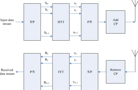
OFDM technique has been popular for next generation communication system. It separates the serial data streams into parallel forms and puts them over orthogonal subcarriers in frequency domain. In recent years, with more developed discrete signal processing (DSP) technique, we can use inverse fast Fourier Transform (IFFT) technique and a parallel-to-serial (P/S) converter to implement this procedure, which is much easier and cost-down compared with using multiple oscillator to generate the subcarrier signals. Due to inter-carrier interference (ICI) resulting from multi-path effect, we need to attach cyclic prefix (CP) at the front of the OFDM symbol. At the receive end, we need a serial-to-parallel (S/P). Then remove CP, do the FFT to convert the time domain signal to frequency domain signal and use a simple parallel-to-serial (P/S) device than we can get our received data streams. Figure 2.1 shows the OFDM transmitter and receiver block diagram.
Figure 2.1: OFDM transmitter and receiver
OFDM technique has great ability against frequency-selective channel since it divides the large bandwidth into small subcarriers, which occupy only a small range of frequency band each. Therefore, one subcarrier can be seen as a small frequency-flat channel. Then in frequency domain, the received OFDM symbol can be simply formulated as the transmit signal multiplied by the channel gain. Therefore we want to use the OFDMA mode, which is based on the OFDM technique to do the multiple-access in our uplink scheduling scheme.
2.2 OFDMA System with Virtual MIMO
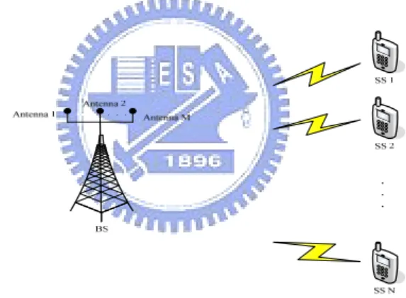
Assume the uplink of the IEEE 802.16 wireless communication system is constructed with OFDMA mode and adjacent subcarriers grouping. One subchannel is composed of q subcarriers, and there are N subchannels in the system. Besides, a single cell environment consisting of one BS and K SSs is considered. Each SS is equipped with one transmit antenna only, while BS may have M receive antennas. These single-antenna SSs and the M-antenna BS form a virtual-MIMO system with an
M-by-K channel matrix if the distributed antennas among K SSs can be seen as virtual
data through the same subchannel as long as the rank constraint is fulfilled, which means the number of SSs using the same subchannel should not be greater than the rank of the channel matrix.
Also, OFDMA/TDD frame structure defined in IEEE 802.16 is considered. In this structure, a frame is divided into two subframes for both downlink and uplink transmission. Durations of DL and UL subframe can be decided by the BS and broadcasted through the downlink map (DL-MAP) and uplink map (UL-MAP) messages to each associated SS. Assume there are L symbols in the uplink map, and then the basic allocation unit will be a slot, which is rectangular-shaped and composed of one subchannel and one OFDMA symbol. Figure 2.2 shows the virtual MIMO system.
Figure 2.2: Virtual MIMO system
2.3 IEEE 802.16 Broadband Wireless Network
IEEE 802.16 is a standard contains various modes for BWA. In this thesis, we consider the point-to-multipoint (PMP) mode in our communication system. In this mode, we consider one BS and multiple SSs. We also consider OFDMA/TDD frame structure defined in IEEE 802.16 in this thesis. In this structure, a frame is divided into two subframes for both downlink and uplink transmission. The duration of DL UL subframe can be decided by the BS and broadcasted through the downlink map
For UL transmission in IEEE 802.16, SS should support multiple types of service flows, which have different QoS constraints individually. IEEE 802.16 MAC support two kinds of grant mechanisms to grant resource to SS: grant per connection (GPC) and grant per SS (GPSS). For GPC, BS grants resource in a flow-by-flow basis; for GPSS, BS only grants a total amount of resource to individual SS. Since BS need to watch the traffic for each service flow in GPC mode, GPSS is more efficient due to the simplicity to keep track of traffic condition on each SS only.
By adopting the Virtual MIMO system and IEEE 802.16 standard, we jointly consider the bandwidth allocation, channel rank constraint, and QoS of each type of service flow in BS. When data traffic arrive in SS, SS sends bandwidth request, and BS will dynamically allocate the subchannel, time slots and power to each SS according to their CSI, mutual interference between SSs, and buffer condition. Then a total amount of bandwidth allocated for service flows in each SS will be granted by BS to SSs.
2.4 Service Types
IEEE 802.16 defines five types of services to support real-time and non-real-time data transmission. Each service type has different QoS requirements, which will be stated as follow:
1) Unsolicited Grant Service (UGS):
UGS supports constant bit rate real-time traffic, such as voice transmission. UGS flows should be granted a fixed amount of resource in each frame, and there is no bandwidth request needed for UGS.
2) Real-Time Polling Service (rtPS):
streaming. It is a delay sensitive traffic so that the delay requirement is an important QoS issue for rtPS. The resource allocation for this type of service should be dynamically arranged according to packet delay requirement, denoted by D , and the dropping rate* should be under the dropping rate requirement. rtPS can use polling mechanism to request more bandwidth if there is a large amount of service flow in the buffer or the delay requirement is going to be violated.
3) Non-real-time Polling Service (nrtPS):
nrtPS is designed to support delay-tolerant data streams while a minimum transmission rate for SS k is required, denoted as Rk*,min. There are nrtPS flows such as HTTP traffic., The nrtPS flow can use polling service to request bandwidth according to the buffer condition or minimum rate requirement.
4) Best Effort (BE):
This type of service is non-QoS guaranteed. BE service is always the lowest priority and will be transmitted when the system resource is still available after scheduling UGS, rtPS and nrtPS services. Therefore BE can use only remaining resource in the system.
In this thesis, the proposed GGRA scheme uses a rate assignment strategy with the predefined residual lifetime, which represents the number of available frame delay according to the head-of-line packet size and delay bound (minimum rate requirement) for UGS and rtPS (nrtPS) traffic, in order to dynamic adjust the priority of each traffic and guarantee the QoS.
2.5 Power Allocation
power based on the required SINR. Since we use virtual MIMO OFDM system, the transmitted signal of user k on subchannel n at the th OFDMA symbol, denoted by
, k n s , can be represented by , , , , k n k n k n s = ρ d (2.1)
where the ρ and k n, dk n, are the allocated power and the QAM data symbol of user
k on subchannel n at the th OFDMA symbol, 1≤ ≤k K,1≤ ≤n N,1≤ ≤ . Note L
that the normalized QAM modulation is used so the data symbol has unitary mean energy. We assume the channel response is almost constant in the interval between SS report and transmission, so we can omit the OFDM symbol index l here. Therefore, the power of user k on subchannel n is hk n, throughout the time interval. Then the received symbol on subchannel n at the th OFDMA symbol, denoted by y , can be n
expressed as , , , , 1 , K n k n k n k n k n k y h ρ d z = =
∑
+ (2.2)where zk n, is the additional white Gaussian noise (AWGN) with zero mean and variance σ2. Then the received SINR of user k on subchannel n at the th OFDMA symbol, denoted by SINRk n, , can be calculated as bellow:
2 , , , 2 2 ', ', ' . k n k n k n k n k n k k h SINR h ρ ρ σ ≠ = +
∑
(2.3)Since we want to achieve the target BER and have good system performance, we have to find the power allocation to combat the noise and interference effect while maximizing the system throughput. There is a tight bound of the BER when using
1.5 1 0.2 . SINR Q BER e − − ≤ i (2.4)
Therefore we can get the minimum SINR of user k, represented by SINR , to achieve k*
the target BER for user k, denoted byBER , by using the following inequality: k*
* * ( 1) ln(5 ) . 1.5 k k Q BER SINR ≥− − (2.5)
Since SINR is determined by the power of user k and other users scheduled in the same subchannel, it is quite complicated to determine the transmission power by a total-user consideration. Zhang and Letaief have proposed a method to deal with the spatial multiple-access of MIMO-OFDM systems in [12]. The mutual channel correlation for each pair of users k1 and k2, denoted by Cork k1,2, is assumed to be
independent of subchannel and defined as
1 2 1 2 1 2 1 2 1 2 ,
1 exp( 2 (sin( ) sin( ))) 1
,
1 exp( 2 (sin( ) sin( )))
1, , Rx Rx k k Rx Rx k k Rx Rx k k k k Rx Rx k k d j M d M Cor j π θ θ λ θ θ π θ θ λ θ θ ⎧ − − ⎪ ≠ ⎪ = ⎨ − − ⎪ ⎪ = ⎩ (2.6)
where j is the imaginary part of complex number, d is the distance between the two transmit antenna,
i
Rx k
θ is the direction of arrival (DOA) of ki’s signal, i=1 or 2, and
λ is the wavelength of the subcarrier. It also shows that the user interference can be almost perfectly cancelled by the multi-user detector (MUD) if we put low correlation users into the same subchannel [10]. Thus, if low (high) correlation SSs are aggregated into different (the same) group and allocated to the same (different) slots, the interference term in (2.3) can be cancelled and SINRk n, can be obtained by
2 , , , 2 . k n k n k n h SINR ρ σ = (2.7)
Therefore, the ρ to achieve k n, BER can be calculated by * * 2 , 2 , ( 1) ln(5 ) . 1.5 k n k n Q BER h σ ρ =− − (2.8)
Each subchannel is composed of q subcarriers, so the power of user k in subchannel n, denoted by pk n, , can be obtained by
, ,
.
k n k n
Chapter 3
Rate Assignment Strategy and Problem
Formulation
3.1 Rate Assignment Strategy
In this thesis, a rate assignment strategy is designed for efficient resource allocation, where the rate assignment for each service class is dynamically adjusted according to a defined residual lifetime. Denote F as the residual lifetime for k s,
service type s of SS k, {s∈ UGS rtPS nrtPS BE, , , }. The residual lifetime represents the number of frames for the service flow remaining to finish the transmission. The SS with a smaller residual lifetime should have a higher priority. The Fk UGS, is set to be equal to the delay bound and decreased one frame by frame. The Fk rtPS, can be obtained by * , , , k rtPS rtPS k rtPS F =D −F (3.1) where * rtPS
D is the delay bound of rtPS traffic and Fk rtPS, is the experienced delay of
from the nrtPS minimum transmission rate R*k,min. Denote the number of remaining bits of head-of-line (HOL) packet for service class s of user k by HOLk s, ,
{ , , , }
s∈ UGS rtPS nrtPS BE , the number of previously transmitted bits of nrtPS packet of user k by Tk nrtPS, , and the previous active frame number for nrtPS transmission of user k by τk nrtPS, . Since we want to fulfill the minimum rate requirement, the maximum number of frames allowed for the packet to transmit, denoted by *
nrtPS
D ,
should make the average transmission rate larger than Rk*,min. Therefore * nrtPS D can be calculated by , , * , * ,min k nrtPS k nrtPS nrtPS k nrtPS k T HOL D R τ ⎢ + ⎥ =⎢ ⎥− ⎢ ⎥ ⎣ ⎦ (3.2)
Then Fk nrtPS, can be obtained by
*
, , .
k nrtPS nrtPS k nrtPS
F =D −F (3.3)
where Fk nrtPS, is the experienced delay in number of frames for the HOL packet of nrtPS user k. For FBE, we do not ensure its QoS. However, a very low minimum
transmission rate can be set for BE traffic to avoid starvation of its service packet transmission. Therefore, FBE can be calculated by the method same as nrtPS traffic.
The rate assignment strategy which determines the allocation resource for each selected SS and allocates the number of bits for service class s of user k, denoted by
, , { , , , }, 1
k s
* * , , , , , * * , , , , , , * , , , , / bits, if 0.75 (L1) min{2 / , } bits, if 0.5 0.75 (L2) min{4 / , } bits, if 0.25 0.5 k s k s k s k s k s k s k s k s k s k s k s k s k s k s k s k HOL F F F F HOL F HOL F F F R HOL F HOL F F F ≤ ≤ ⋅ ≤ ≤ = ⋅ ≤ ≤ * , * , , , (L3) bits, if 0.25 , (L4) s k s k s k s HOL F F ⎧ ⎪ ⎪ ⎨ ⎪ ⎪ ≤ ⎩ (3.4)
where Fk s*, denotes the residual lifetime of the HOL packet when entering the queue. When an SS is selected, this strategy can help the scheduler give more resource to more urgent service, and then ensure the QoS. The strategy (3.4) gives the average minimum rate for each service at level 1 (L1), and doubles the rate when the service enters the next level. At level 4 (L4), the HOL packet for service s of user k is force to be totally sent out to avoid QoS violation. This mechanism saves the resource when the traffic is not urgent and gives it to urgent traffic by assigning more transmission bits. After we decide the allocation bits for each class, we need to do consistent allocation, which represents that the data of different services for the same SS should be aggregate together in order to reduce the transmission overhead.
3.2 Problem Formulation
In this thesis, the proposed genetic algorithm with SS grouping resource allocation (GGRA) scheme intends to maximize the system throughput while satisfying QoS requirements for all SSs and subjecting to some system constraints. The allocation problem is to decide the optimal user-subchannel pair and the corresponding modulation order. Denote x to indicate the number of bits carried k n,
by the modulation order for each subcarrier in subchannel n of user k in the th OFDMA symbols, 1≤ ≤k K, 1≤ ≤n N,1≤ ≤ , which is given by L
, 0, if not assigned, 2, if QPSK modulation is assigned, 4, if 16-QAM is assigned, 6, if 64-QAM is assigned. k n x ⎧ ⎪ ⎪ = ⎨ ⎪ ⎪⎩ (3.5)
Then we can denote the assignment vector to be the allocation results for the th OFDMA symbol for all users:
1,1, 1,2, , 1, , , ,1, ,2, , , , , ,1, ,2, , , . T N k k k N K K K N x x x x x x x x x ⎡ ⋅⋅⋅ ⋅⋅⋅ ⋅⋅⋅ ⋅⋅⋅ ⋅⋅⋅ ⎤ ⎣ ⎦ x (3.6)
Finally, as the assignment matrix for the OFDMA UL frame consisting L OFDMA symbols, denote by x , is given by
1
, , , L .
⎡ ⋅⋅⋅ ⎤
⎣ ⎦
x x x x (3.7)
Since one subchannel is composed with q subcarriers, the total allocated bits to user k in the UL subframe, denote asR , can be calculated by k
, 1 1 . L N k k n l n R q x = = ⋅
∑∑
(3.8)The GGRA scheme proposed in this thesis aims to determine a optimal assignment matrix in each frame to maximize the overall system throughput while satisfying QoS requirements of each type of service flow for every user. There are three constraints we need to concern about when designing the allocation algorithm, which are stated as follows.
1) Power constraint:
The maximum transmission power of one SS in one OFDM symbol should have a limitation. We denote pk,max as the maximum allowable uplink transmission
power and obtain the power constraint as follow:
, ,max 1 , , . N l k n k n p p l k = ≤ ∀
∑
(3.9)2) Rank constraint:
In virtual-MIMO system, the number of SS transmitting data stream in one subchannel should be lower than the rank of channel matrix. Due to abundant paths in urban area, it is reasonable to assume the channel is full rank in order to simplify this problem. Since the BS has M antennas only (therefore the channel rank equals M in full rank case), the rank constraint can be obtained as
, 1 sgn( ) , , . K l k n k x M n l = ≤ ∀
∑
(3.10) 3) Buffer constraint:We assume that the number of bits for service class s in the buffer of user k is B , k s,
Thus the total number of bits in the buffer of all service classes for user k, denoted as B , can be obtained by summing all service types of k B : k s,
, , .
k k s
s
B =
∑
B ∀k (3.11)Since the system should make full utilization for the limited radio resource, the resource should not be given more than the SSs’ number of bits in the buffer, which may lower the transmission efficiency. Therefore we should define the buffer constraint as
, .
k k
R ≤B ∀ (3.12) k
Under the three system constraints and the rate assignment strategy, the GGRA scheme want to select one optimal assignment matrix * [ 1*, 2*,..., *]
x x x xL
to maximize the system throughput and to achieve full utilization of the system. Finally, the allocation problem can be mathematically formulated as optimization equations given by
Objective: x 1 arg max ( ) K k k R = =
∑
* x x (3.13)Subject to the system constraints:
, ,max 1
, 1
(i) Power constraint: , 1 ,1 ,
(ii) Rank constraint: sgn( ) , 1 ,1 , (iii) Buffer constraint: , 1 ,
N k n k n K k n k k k p p k K L x M n N L R B k K = = ≤ ≤ ≤ ≤ ≤ ≤ ≤ ≤ ≤ ≤ ≤ ≤ ≤
∑
∑
(3.14)and the rate assignment assignment strategy:
, k , * * , , , , , ,
(i) SS with the lowest is selected first, (ii) when SS is selected, determine by
/ bits, if 0.75 (L1) min{2 / , } bits k s k s k s k s k s k s k s k s F R HOL F F F F HOL F HOL R ≤ ≤ ⋅ = * * , * * , , , * , , , if 0.5 0.75 (L2) min{4 / , } bits, if 0.25 0.5 (L3) bits, if 0.25 , (L4) (iii) each SS should ob
k s k s k s k s k s k s F F F HOL F HOL F F F HOL F F ⎧ ⎪ ≤ ≤ ⎪ ⎨ ⋅ ≤ ≤ ⎪ ⎪ ≤ ⎩ ey consistent allocation, (3.15)
where x is the optimal assignment matrix, * pk,max is the maximum allowable power for SS k, B is the total number of bits in the buffers for all service types of k
SS k, and R is the allocated bits to service type s of SS k. Clearly, we can notice k s,
that k k s,
s
R =
∑
R .3.3 Genetic Algorithm for Uplink scheduling
Genetic Algorithm (GA) is a search technique used in computing to find exact or approximate solutions to optimization and search problems. It use techniques inspired by evolution biology such as inheritance, mutation, selection and crossover. A
great GA needs two important part to be defined, genetic representation and fitness function. Genetic representation helps to map the solution domain to the chromosomes, while fitness function helps to evaluate chromosomes, eliminate the bad ones, and keep the better ones. Therefore, the optimal solution can be found after iterative processes. A typical GA method can be shown below:
1. Generate initial population
2. Evaluate the fitness of each individual population 3. Repeat
1) Select best-ranking individuals to reproduce
2) Breed new generation by crossover and mutation and give birth to offspring. 3) Evaluate the individual fitness of offspring
4) Replace worst ranked part of population with offspring
4. Termination when iteration limit or convergent condition is reached.
To solve the optimization problem given in (16)-(18), the proposed GGRA scheme adopts genetic algorithm (GA) to solve the optimization problems, where each SS group is regarded as a GA chromosome in each individual, and these SSs in the same group will be scheduled to different slots to avoid interference. The SS grouping can not only avoid high correlation users’ interference but also help to reduce the number of element in GA individuals.
The GGRA uses GA to permute the SS groups’ order, define appropriate fitness function, and search the best solution. The gth chromosome in ith individual, defined by group number Φ , is the basic element in each individual. The ith individual, i g, denoted by C , is consisted of a number of SS groups with non-regular order and i
defined as
,1 , ,
[ ,..., ,..., ],
i i i g i G
C = Φ Φ Φ (3.16)
where G is the number of groups in Ci. Assume Φ contains i g, κ SSs and is expressed as
, { ,1, ,2,..., , ].
i g SSg SSg SSgκ
Φ = (3.17)
Then each individual represents a different scheduling order of groups in the currently scheduled frame. Notice that the GA uses crossover and mutation method to change the order of chromosomes. Since we want to maximize the throughput with QoS guarantee, a predefined fitness function, denoted by Π , is defined to evaluate the individuals, which is given by
( , ) e , k k k k R R q W α ν ν − ⋅ Π = ⋅ ⋅
∑
∑
(3.18)where α is a constant to control the exponential decay, ν is the unsatisfied ratio, obtained by the number of bits for UGS, rtPS, and nrtPS unsatisfied service traffic divided by the total number of bits of the original HOL packet, and W represents the total number of used slots in the current scheduled frame. Π can be seen as two terms: spectrum efficiency and unsatisfied ratio. As a result, we can choose I individuals with the best throughput and the least QoS violation after several iterations, and the final optimal solution for (3.13)-(3.15) can be achieved.
Chapter 4
Genetic Algorithm with SS Grouping
Resource Allocation
To solve the optimization problem given in (16)-(18), a genetic algorithm with subscriber station (SS) grouping resource allocation (GGRA) scheme is proposed. The GGRA scheme first aggregates high correlation SSs together as a group since user correlation in a virtual MIMO system may lead to large interference and severe performance degradation. The SS grouping is formed by choosing an SSi and
selecting all other SSs which have high correlation with SSi. Then the GGRA scheme
adopts genetic algorithm (GA) to solve the optimization problems. Then GGRA uses GA to permute the SS groups’ order. When allocating resource to each SS, residual lifetime and rate assignment strategy defined in previous chapter are applied. If there is any remaining resource, the GGRA uses residual resource reallocation (RRR) to fully utilize the system. Finally the allocation results of each individual are evaluated by the fitness function. The best scheduling result will be chosen by the individual with best fitness value after iteration. The proposed GGRA scheme can be divided to four steps: SSs grouping, genetic algorithm, residual resource reallocation, and fitness calculation, which are described in detail below.
4.1 SS Grouping
The SS grouping can avoid high correlation users’ interference, and it also helps to reduce the number of element in GA individuals. According to [12] , given the correlation threshold δ , we can choose SSs with correlation higher than δ into the same group and form I permutations of G groups for individual Ci. If there is any SS
which doesn’t has correlation higher than δ with other SSs, then itself will become one group. Finally, each group may contain one or several SSs. Theses group will be a basic element of individuals for genetic algorithm, and members in one group will be put into different subchannels to prevent high mutual interference. After SSs grouping, the G groups will be the G chromosomes for each individual Ci and be used in
genetic algorithm.
4.2 Genetic Algorithm
Next, GGRA uses these G groups to generate the populations and run the genetic algorithm to determine the scheduling order of each group. Notice that SSs in the same groups have high channel correlations. Therefore we will allocate them according to their number order in the group since they have similar channel condition in the neighboring subchannel. So the individual in the population may be formed as a one-dimensional matrix as follow:
,1 ,2 , , ,1 ,2 , [ , ,... ], { , ,..., ]. i i i i G i g g g g k C where SS SS SS ′ = Φ Φ Φ Φ = (4.1)
Ci represents the ith individual in the crossover and mutation pool, consisted of the
arbitrary order of group number. Each group is made by the grouping mentioned in the first step. Therefore we totally have I individuals in the crossover pool. Each can
represents one kind of permutation of group order, which can be easily translated to SSs’ permutation order. Then we can randomly choose two individuals and do the crossover and mutation. It can be explained by the following example:
1 2 [2, 3,1,13, ,11, 9,12,5,10] [ 4,8,14,15, 6, 7 1,11,12, 3,10,1 9,8, 6,5, , 4, 7,13, 2,15] .. 4 .... C C = = (4.2)
In (4.2), we form two individuals to do the crossover and mutation. In this thesis, first we use two-point crossover method. So we choose the fifth to tenth elements in the two individuals and exchange them, and then we can have the following results:
1 2 3 1 11 12 10 [2, , ,13, , , 9, , 5, ] [9, , , 5, , , ,13, 2, ] 1,11,12, 3,10,14 4,8,14, 8 6 15 ,, 6 7 4 7 15 C C ′ = ′ = (4.3)
We can see that elements 3, 1, 11, 12 and 10 in C1, and 8, 6, 4, 7 and 15 in C2 are
duplicated. Since each element represents the group number for scheduling order, it is unnecessary to have SSs in one group to be scheduling twice in one frame. Therefore we pick them up and use random permutation to form another pair of duplicate matrices: 1 2 [10,12,1,11,3] [15, 4, 7, 6,8]. D D = = (4.4)
Now we can exchange the two matrices and put these elements back into the crossover result matrices. Notice we only change the duplicate terms but leave the crossover terms remain the same. This step can be seen as mutation since it happened randomly when duplicated terms occur. Then we can get the final results:
1 2 [2,15 4, ,13, , , 9, , 5, ]7 6 8 10 [9, , , 1,11,12,3,10,14 4,8,14,15, 6, 7 125, , ,111,1 ,3 2, ].3 C C = = (4.5)
offspring.
Since the genetic algorithm is implemented in BS end, the BS is assumed to have high computational ability. Therefore, all individuals are forced to do the crossover to have a better convergence speed. As a result, there will be totally 2I individuals after the crossover. After crossover and mutation, we can determine the SSs’ scheduling order. Then we can use the power loading equation in (2.8) and (2.9) to determine the modulation order under power constraint, and use the rate assignment strategy defined in section III to determine the allocated data bits to each user. Then the required number of slots can be calculated by ⎡⎢Rk /q x⋅ lk n, ⎤⎥ . After the
calculation above, these slots will be allocated to SS k by the dedicated modulation order. If there are still remain bits in the slots, they will be given to each service class of SS k proportionally to their service queue length. If all slots are allocated to SSs less than the channel rank, we start the remaining allocation from the first subchannel again until the rank constraint is reached.
For high traffic load case, this allocation method can fill all the slots and make the system full utilization. However, there may be some case with low traffic load or only a few users in the system. In this case, some slots may remain free and make the system under-utilized. Therefore, the GGRA scheme uses the residual resource reallocation (RRR) to allocate these free slots.
In each remaining slot, GGRA will check the system constraints, such as power and buffer constraints for each SS and rank constraint for the system, and find the available SSs which can use the current slot under constraints. Then the scheduler gives the slot to the SS which is available and support the highest modulation order. Notice that each selected SS can transmit its four kinds of service in its given slot.
queue. RRR can help to decrease the delay of each packet in low traffic intensity, and it can also help to satisfy the QoS by relaxing the bursty traffic periods.
After RRR, we have determined the UL-MAP and are able to get the possible spectrum efficiency and unsatisfied ratio. Each individual is linked to one kind of allocation result, so these 2I individuals can be evaluated by the fitness function in (3.19). Then the best I individuals with higher fitness will be selected to become the offspring. If the iteration number doesn’t reach the upper bound, the GGRA scheme will continue from the crossover and mutation in genetic algorithm again. The final scheduling result will be determined when the iteration upper bound is reached or the fitness of each individual converges. Then the individual with the highest fitness value will be chosen, and its related allocation result will become the final solution.
Chapter 5
Simulation Results and Discussions
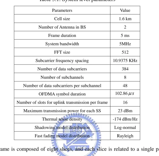
In the simulation, the system level parameters of uplink OFDMA environment are set to be compatible with the IEEE 802.16m Evaluation Methodology Document (EMD) [13]. The large scale fading and small scale fading are both considered, and the path loss is modeled as 128.1 37.6 log+ X (dB), where X is the distance between the BS and SS in unit of kilometers. The power delay profile follows the exponential decay rule. Finally, the channel state is assume to be fixed within one frame and varies frame by frame with time according to the fading model stated above. Table 1 shows the system level parameters.
The source model and QoS Requirements also follow the IEEE 802.16m evaluation methodology document (EMD) [13]. Four types of traffic corresponding to UGS, rtPS, nrtPS, and BE are considered in the simulation scheme. The first one is the voice traffic for UGS, which is modeled as the ON-OFF model with ON(OFF) period is exponentially distributed with mean as 1 second (1.35 seconds). During the ON period, one packet is generated every 20ms with fixed size of 28bytes, payload and header both included. The second type of service is video streaming traffic for rtPS. It consists of a sequence of video frames generated every 100 ms regularly. Each
Table 5.1: System level parameters Parameters Value Cell size 1.6 km Number of Antenna in BS 2 Frame duration 5 ms System bandwidth 5MHz FFT size 512
Subcarrier frequency spacing 10.9375 KHz Number of data subcarriers 384
Number of subchannels 8 Number of data subcarriers per subchannel 48
OFDMA symbol duration 102.86μs Number of slots for uplink transmission per frame 16
Maximum transmission power for each SS 23 dBm Thermal noise density -174 dBm/Hz Shadowing model distribution Log-normal Fast fading model distribution Rayleigh
video frame is composed of eight slices, and each slice is related to a single packet. The size of each slice packet is truncated Pareto distributed, and the inter-arrival time of two consecutive packets is also truncated Pareto distribution. The third service type is the web browsing HTTP traffic for nrtPS. It is modeled as a sequence of webpage downloads, and each page is composed of several packet arrivals. It can be separated as a main object and some embedded objects which can be divided into several packets and the maximum transmission unit (MTU) is 1500 bytes, header included. The inter-arrival time between two pages is exponentially distributed with mean time as 30 seconds. The main objects and embedded objects are both truncated lognormal distributed with mean of 10710 bytes and 7758 bytes, respectively. The last type is the FTP traffic for BE. It is modeled as a sequence of file downloads. The size of each file is in truncated lognormal distributed with mean of 2 MB, standard deviation of 0.722
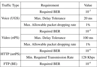
Table 5.2: QoS requirements of each service type
Traffic Type Requirement Value Required BER 10-3 Max. Delay Tolerance 20 ms Voice (UGS)
Max. Allowable packet dropping rate 1% Required BER 10-4 Max. Delay Tolerance 100 ms Video (rtPS)
Max. Allowable packet dropping rate 1% Required BER 10-6 HTTP (nrtPS)
Min. Required Transmission Rate 128 Kbps
FTP (BE) Required BER 10-6
MB, and a maximum value of 5MB. The inter-arrival time of two consecutive files is exponentially distributed with mean of 180 seconds. We can calculate the arrival rates of the UGS, rtPS, nrtPS and BE by the traffic models mentioned above, which are 4.8Kbps, 64Kbps, 14.5Kbps, and 88.9Kbps, respectively. The QoS requirements of each service type are defined in table 2. Besides, the minimum transmission rate of BE traffic is set as 1 byte per frame for calculating F in GGRA scheme. BE
In the thesis, we compare the proposed GGRA scheme with the other two QoS- aware scheduling algorithm, EFS [7] and MLWDF [8]. The EFS scheme uses a strictly defined priority while the MLWDF scheme uses predefined function to dynamically adjust the transmission priority of the UGS, rtPS, and nrtPS packets. However, if the high priority services are limited by the power or interference issues, the EFS and MLWDF admits the low priority packets to be sent out in the free slots. Besides, the scheduling results should be given in the frame duration. Therefore the computation time of each scheduling algorithm is concerned as well.
In the simulation, the number of SSs varies from 10 to 80, and each of them contains all the four types of services. The highest transmission rate in a frame is achieved when the highest modulation order is assigned to two low correlation SSs in
each slot, which equals to 14.7456 Mbps. The traffic intensity is defined as the ratio of the total average arrival rate of four service types of all users over the maximum transmission rate. The following performance metrics will be measured: (i) system throughput, (ii) packet dropping rate of UGS and rtPS packets, (iii) ratio of unsatisfied HTTP users (packets), defined by the number of SSs (packets) which has average HTTP transmission rate is less than the minimum required rate over the total number of HTTP users (packets). (iv) BE throughput, and (v) Computation time.
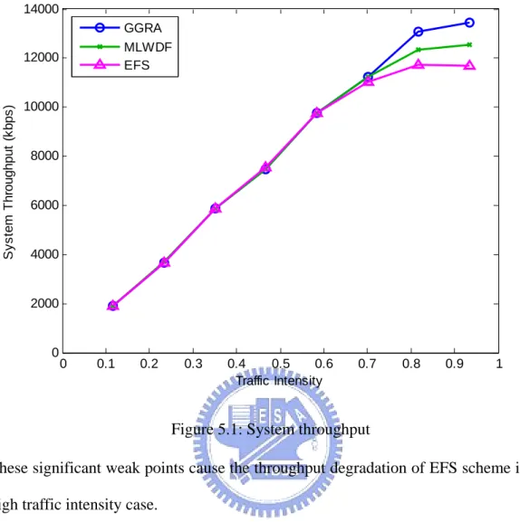
First, Figure 5.1 shows the system throughput of the three resource allocation schemes. In this figure, the three schemes have similar throughput in low-medium traffic intensity cases because the system can sufficiently support the four types of service and easily fulfill the QoS requirements of UGS, rtPS and nrtPS. However, in high traffic intensity case, the GGRA scheme has the highest throughput among the three allocation schemes. It is because the GGRA adopts the residual lifetime of the service traffic to dynamically allocate resource and thus their QoS requirements can be satisfied. It also uses the genetic algorithm to find the optimal allocation map and thus the spectrum efficiency can be maximized. The GGRA scheme can allocate the service traffic more precisely and efficiently. On the other hand, the MLWDF can dynamically adjust the traffic priority as GGRA scheme by a predefined function. However, it considers one allocation slot a time rather than the whole frame as GGRA does. Thus such a local optimal solution done by MLWDF cannot achieve high throughput as the global optimal solution done by GGRA. This is the major distinct between these two schemes. The EFS serves the highest priority traffic first. Therefore it may allocate slots to the SS which has a higher priority service but cannot support high modulation order. Moreover, EFS considers one slot a time as MLWDF does.
0 0.1 0.2 0.3 0.4 0.5 0.6 0.7 0.8 0.9 1 0 2000 4000 6000 8000 10000 12000 14000 Traffic Intensity S y s te m T hr o ug hp ut ( k bp s ) GGRA MLWDF EFS
Figure 5.1: System throughput
These significant weak points cause the throughput degradation of EFS scheme in the high traffic intensity case.
Next, Figure 5.2 shows the packet dropping rate of the voice traffic. All the three allocation schemes can achieve almost zero voice packet dropping rates for all case. It is because the proposed GGRA scheme grants resource according to the rate assignment strategy and the predefined residual lifetime. The rate assignment strategy can grant resource to the voice traffic efficiently because voice packets have small delay tolerances and small packet sizes. GA also helps to make efficient allocation, so the urgent voice packet can be sent out before reaching the delay bound. On the other hand, the MLWDF scheme dynamically considers the channel gain and the weighted delay. Thus it can take care of the UGS, rtPS and nrtPS traffic in a fair way. Therefore MLWDF can achieve a very low the voice dropping rate as GGRA. Besides, the EFS
0 0.1 0.2 0.3 0.4 0.5 0.6 0.7 0.8 0.9 1 0 0.003 0.006 0.009 0.012 0.015 Traffic Intensity V oi c e P ac k et D rop pi n g R a te GGRA MLWDF EFS Figure 5.2: Voice packet dropping rate
scheme always serves the voice packet prior to other service classes. Thus it can achieve zero voice packet dropping rate in the simulation results for all traffic cases. However, the EFS scheme serves the high priority service in such a conservative way, which leads to worse performance than the GGRA scheme when concerning about lower priority service flows.
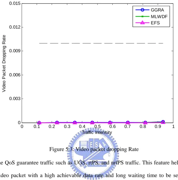
Next, Figure 5.3 shows the video packet dropping rate among the three schemes. It has a similar trend as Figure 4.2. The rate assignment strategy in GGRA scheme can adjust the transmission bits of video traffic according to the residual lifetime. It can allocate more resource to video packets if in more urgent case and keep a very low video packet dropping rate. The optimal solution found by GA also helps to allocate video traffic more flexible as long as it maximize the spectrum efficiency and save more resource for urgent flows. The MLWDF scheme dynamically assigns resource to
0 0.1 0.2 0.3 0.4 0.5 0.6 0.7 0.8 0.9 1 0 0.003 0.006 0.009 0.012 0.015 Traffic Intensity V ide o P ac k et D rop pi n g R a te GGRA MLWDF EFS
Figure 5.3: Video packet dropping Rate
the QoS guarantee traffic such as UGS, rtPS, and nrtPS traffic. This feature helps the video packet with a high achievable data rate and long waiting time to be sent out prior to other services. Thus MLWDF can achieve a very low video packet dropping rate as it did for voice packet. On the other hand, the EFS scheme allocates resource to video traffic right after it serve small size packets of voice traffic. In other words, it sacrifices the performance of nrtPS and FTP traffic to guarantee the high priority service flows. As a result, the voice packet dropping rate can keep close to zero for all traffic intensity case.
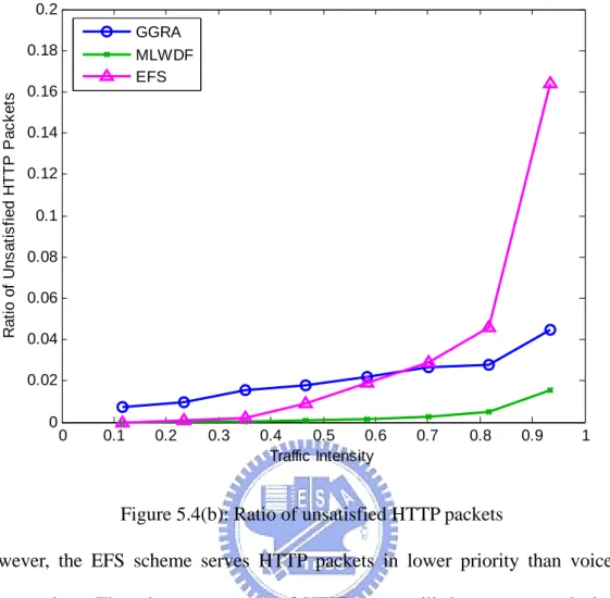
Next, Figure 5.4(a) and Figure 5.4(b) show the ratio of unsatisfied HTTP users and packets, respectively. The ratio of unsatisfied HTTP packets is defined as the number of HTTP packets which is not served such that the average HTTP transmission rate of the user is under the minimum rate requirement over the total
0 0.1 0.2 0.3 0.4 0.5 0.6 0.7 0.8 0.9 1 0 0.02 0.04 0.06 0.08 0.1 0.12 0.14 0.16 0.18 0.2 Traffic Intensity Ra ti o o f Un s a ti s fi e d H T T P Us e rs GGRA MLWDF EFS
Figure 5.4(a): Ratio of unsatisfied HTTP users
HTTP packets. In this case, we can see that GGRA can maintain a low percentage of unsatisfied HTTP packets. Although the unsatisfied ratio of HTTP packets in GGRA case is higher than those of other cases in low traffic scheme, GGRA can maintain zero unsatisfied users under traffic intensity up to 0.8, and a very low unsatisfied ratio for traffic intensity larger than 0.9. This is due to that GGRA considers a long term average rate requirement for each HTTP user, and the rate assignment strategy can give more resource to HTTP users when the long term rate is below the minimum rate requirement. Therefore, if one packet is consider unsatisfied, the GGRA scheme will give a lower residual lifetime to the next HTTP packet of this user, and force to send it out more quickly by the rate assignment strategy. Finally the overall HTTP rate will be compensated and keep above the minimum rate requirement. MLWDF scheme consider HTTP fairly as GGRA scheme, so it can keep a low unsatisfied ratio as well.
0 0.1 0.2 0.3 0.4 0.5 0.6 0.7 0.8 0.9 1 0 0.02 0.04 0.06 0.08 0.1 0.12 0.14 0.16 0.18 0.2 Traffic Intensity R at io of U ns at is fi ed H T T P P a c k et s GGRA MLWDF EFS
Figure 5.4(b): Ratio of unsatisfied HTTP packets
However, the EFS scheme serves HTTP packets in lower priority than voice and video packets. Thus the average rate of HTTP users will decrease severely in high traffic case and cause high ratio of unsatisfied HTTP users.
Next, Figure 5.5 shows FTP throughputs of the three allocation scheme. The arrival rate of FTP traffic is much higher than other service traffic, so the FTP throughput degradation will severely affect the system throughput. We can see the FTP throughput of GGRA increase until traffic intensity larger than 0.8. This phenomenon is because of the cooperation of GA and rate assignment strategy. The two mechanism in GGRA helps to save more resource for FTP traffic since the UGS, rtPS, nrtPS traffic can fulfill their QoS under a lower rate. The MLWDF considers a local optimal allocation and dynamically assign resource to each service. Besides, if the high priority service is forbidden to be sent out due to power or interference issue,
0 0.1 0.2 0.3 0.4 0.5 0.6 0.7 0.8 0.9 1 0 1000 2000 3000 4000 5000 6000 7000 8000 9000 Traffic Intensity F T P T h ro ug hp ut ( k bp s ) GGRA MLWDF EFS Figure 5.5: FTP throughput
the FTP packets can still be allocated in the current frame. This relaxation raises the FTP throughput of the MLWDF scheme. In EFS case, the scheduler forces to send out high priority packet as soon as possible rather than just fulfill the QoS. This mechanism not only suppresses the transmission opportunity of EFS, but also reduces the spectrum efficiency, which further degrades the performance of FTP service. As a result, the EFS scheme has the worst FTP throughput among the three schemes.
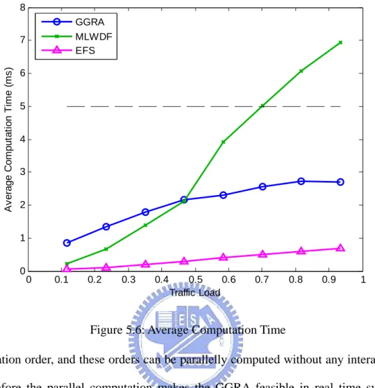
Finally, Figure 5.6 shows the computation time of the three resource allocation schemes. GGRA needs the most computation time in low traffic case since it needs to do crossover and mutation to generate new individuals, and each individual has a new fitness value calculated by the new scheduling permutation. However, as Figure 5.6 shows, the computation time can be reduced to less than 3ms, which is lower than the frame duration. It is because that each individual in GA can be linked to one
0 0.1 0.2 0.3 0.4 0.5 0.6 0.7 0.8 0.9 1 0 1 2 3 4 5 6 7 8 Traffic Load A v erage C o m pu tat ion T im e (m s ) GGRA MLWDF EFS
Figure 5.6: Average Computation Time
allocation order, and these orders can be parallelly computed without any interaction. Therefore the parallel computation makes the GGRA feasible in real time system. EFS and MLWDF use heuristic search method to give resource to the user with the highest priority or the largest MLWDF function value. Therefore the allocation can be done in a short computation time for EFS under all traffic intensity case and for MLWDF for low traffic intensity case. However, the computation of MLWDF increases tremendously. It is because the relaxation of FTP packet transmission opportunity mentioned above. This relaxation needs to check the FTP queues of each SS after sorting the QoS guarantee traffic and takes much computation time. Therefore the computation time increases and even exceeds the frame duration in high traffic case, which shows that the MLWDF is unfeasible when the system is highly loaded.
Chapter 6
Conclusions
In this thesis, the genetic algorithm with SS grouping resource allocation (GGRA) scheme is proposed for IEEE 802.16 uplink system to support the four types of traffic, including UGS, rtPS, nrtPS and BE service. The GGRA scheme intends to maximize the system throughput under the system constraints and QoS requirements. The proposed GGRA scheme performs SS grouping to separate high correlation SSs. An originally designed rate assignment strategy equipped with predefined residual lifetime is proposed and applied in GGRA scheme to allocate resource efficiently. The strategy uses the residual lifetime to dynamically adjust the priority of different service class. It also divides the residual lifetime into four levels to dynamically decide the transmission data bits of each service, which save more resource for urgent traffic and maintain the QoS. The GGRA scheme also applies genetic algorithm to find the optimal allocation results, which makes a much more suitable scheduling decision than other heuristic approaches. It is proved by the simulation results that the cooperation of rate assignment strategy and genetic algorithm can help the system properly allocates resource to each service. Under low traffic case, the proposed GGRA scheme also helps the system utilization by RRR, which gives resource to SS with high channel gain. Therefore the simulation results show that the GGRA scheme
has a better system throughput compared with the EFS scheme and MLWDF scheme. When concerning the computational complexity, the feasible computation time achieved by GGRA, which is under the frame duration, is also convinced that GGRA is suitable for real time system.
Bibliography
[1] IEEE Std. 802.16- 2004, “IEEE Standard for Local and Metropolitan Area Networks Part 16: Air Interface for Fixed Broadband Wireless Access Systems,” Oct. 2004.
[2] IEEE Std. 802.16e, “IEEE Standard for Local and Metropolitan Area Networks Part 16: Air Interface for Fixed Broadband Wireless Access Systems Amendment for Physical and Medium Access Control Layers for Combined Fixed and Mobile Operation in Licensed Bands,” Oct. 2005.
[3] D. Niyato and E. Hossain, “Queue-Aware Uplink Bandwidth Allocation for Polling Services in 802.16 Broadband Wireless Networks,” IEEE
GLOBECOM ’05, vol. 6, 28 Nov.-2 Dec. 2005.
[4] J. Sun, Y. Yao, and H. Zhu, "Quality of Service Scheduling for 802.16 Broadband Wireless Access Systems," IEEE VTC 2006-spring, vol. 3, pp. 1221-1225, 2006. [5] Y. Ben-Shimol, I. Kitroser, and Y. Dinitz, “Two Dimensional Mapping for
Wireless OFDMA Systems,” IEEE Trans. Broadcasting, vol. 52, Issue 3, pp. 388-396, September 2006.
[6] J.Wang, K. Araki, Z. Zhang, Y. Chang, H. Zhu, and T. Kashima, “A Low Complexity Tree-Structure Based User Scheduling Algorithm for Up-Link Multi-user MIMO systems,” IEICE Trans. Commun., Vol. E90-B, No. 6, pp. 1415-1423, June 2007.
[7] V. Singh and V. Sharma, “Efficient and fair scheduling of uplink and downlink in IEEE 802.16 OFDMA networks,” IEEE Wireless Communication and Networking
Conference (WCNC2006), vol. 2, pp. 984-990.
[8] W. Park, S. Cho, and S. Bahk, “Scheduler design for multiple traffic classes in OFDMA networks,” IEEE International Conference on Communications, vol. 2, pp. 790-795, June 2006.
[9] Y. B. Reddy, N. Gajendar, P. Taylor, and D. Madden, “Computationally Efficient Resource Allocation in OFDM Systems: Genetic Algorithm Approach,” Proceedings of the International Conference on Information Technology, pp. 36-41, 2007.
[10]Q. Guo, S. C. Kim, and D. C. Park, “Antenna Selection Using Genetic Algorithms for MIMO systems,” IEICE Trans. Fundamentals, Vol. E89-A, No. 6, pp.1773-1775, June 2006.
[11] A. J. Goldsmith, and S. Chua, “Variable-Rate Variable-Power MQAM for Fading Channels,” IEEE Trans. Commun., Vol. 45, No. 10, pp.1218-1230, Oct. 1997. [12] Y. J. Zhang and K. B. Letaief, “An Efficient Resource-Allocation Scheme for
Spatial Multiuser Access in MIMO/OFDM Systems,” IEEE Trans. Commun., Vol. 53, No. 1, pp. 107-116, Jan. 2005.
[13] IEEE 802.16m-08/004r1, “IEEE 802.16m Evaluation Methodology Document (EMD),” 2008-03-17.
Vita
Yin Chiu was born in Taichung, Taiwan. He received B.E. and M.E. degree in Department of Communication Engineering from National Chiao-Tung University, Hsinchu, Taiwan, in 2006 and 2008, respectively. His research interests include radio resource management and wireless communication systems.