Optimal Design of Two-Channel
Nonuniform-Division FIR Filter Banks
with
1, 0, and
1 Coefficients
Ju-Hong Lee,
Member, IEEE, and Ding-Chiang Tang
Abstract— This paper deals with the optimal design of two-channel nonuniform-division filter (NDF) banks whose linear-phase FIR analysis and synthesis filters have coefficients con-strained to 01, 0, and +1 only. Utilizing an approximation scheme and a WLS algorithm, we present a method to design a two-channel NDF bank with continuous coefficients under each of two design criteria, namely, least-squares reconstruction error and stopband response for analysis filters and equiripple reconstruction error and least-squares stopband response for analysis filters. It is shown that the optimal filter coefficients can be obtained by solving only linear equations. In conjunction with a proposed filter structure, a method is then presented to obtain the desired design result with filter coefficients constrained to01, 0, and+1 only. The effectiveness of the proposed design technique is demonstrated by several simulation examples.
Index Terms— Filter banks, FIR filters.
I. INTRODUCTION
Q
UADRATURE mirror filter (QMF) banks find an im-portant role in the areas of subband coding of speech signals [1], communication systems [2], short-time spec-tral analysis [3], and subband coding of image signals [4]. In these applications, a QMF bank is used to decompose a signal into subbands with equal bandwidth, and the subband signals in the analysis system are decimated by an integer equal to the number of the subbands. However, uniform-subband decomposition is not an appropriate scheme to match the requirements for the subband coding of speech and audio signals. The most appropriate decomposition must consider the critical bands of the ear. It has been mentioned in [5] that these critical bands have nonuniform bandwidths and cannot be easily constructed by conventional tree structure based on two-channel QMF banks. Therefore, it is worth exploiting the design problem of two-channel nonuniform-division filter (NDF) banks.The basic theory regarding the principle and the related conditions of perfect reconstruction for NDF banks has been presented in [5]. Methods for designing NDF banks were also proposed in [5]. However, it is difficult to solve the resulting design problem with nonlinear constraints. In [6], a structure Manuscript received September 23, 1997; revised July 31, 1998. This work was supported by the National Science Council under Grant NSC87-2213-E002-071. The associate editor coordinating the review of this paper and approving it for publication was Dr. Truong Q. Nguyen.
The authors are with the Department of Electrical Engineering, National Taiwan University, Taipei, Taiwan, R.O.C.
Publisher Item Identifier S 1053-587X(99)00756-4.
for NDF banks was introduced, and a design method based on the use of pseudo-QMF was presented. The main drawback of this method is that FIR filters with complex coefficients are required by the resulting NDF bank to reduce the aliasing distortion. Recently, one of the authors considered a structure for two-channel NDF banks and proposed design methods for optimally designing NDF banks based on error criteria in [7].
Although designing a NDF bank has been considered in [5]–[7], hardware implementation for the designed NDF banks generally requires large and complicated digital circuits be-cause these NDF banks are designed with real or complex coefficients. To achieve circuit complexity reduction or to speed up filtering operation besides concern for the overall performance, it is preferable to design a NDF bank with coefficients restricted to 1, 0, and 1 only. However, there are practically no papers concerning the optimal design of NDF banks whose FIR analysis and synthesis filters have coefficients restricted to 1, 0, and 1 only in the literature. In this paper, the NDF banks with the structure similar to [7], as shown in Fig. 1, are considered. We deal with the optimal design and realization of the two-channel NDF bank with 1, 0, and 1 coefficients. First, a method is developed based on an approximation scheme for designing a continuous-coefficient NDF banks with optimal reconstruction response and stopband response for its linear-phase (LP) FIR analysis and synthesis filters in the least-squares sense. This method is further incorporated with the WLS algorithm of [8] to optimally design NDF banks with minimax reconstruction response and stopband response for analysis and synthesis filters. It is shown that the resulting coefficients for the LP FIR analysis and synthesis filters can be found through solving only linear equations. To obtain a design with 1, 0, and 1 coefficients, which achieves the optimal performance, we propose a new filter structure for realization. The coefficients 1, 0, and 1 are used in the oversampled domain, and the design procedure leads to finely quantized coefficients. Simulation results show that very satisfactory NDF banks can be obtained using the proposed technique.
This paper is organized as follows. Section II briefly de-scribes the principle of two-channel NDF FIR filter banks. In Section III, we formulate the associated design problem for a two-channel NDF filter bank with reconstruction response and filter stopband response. A design method based on an approximation scheme is presented for solving the re-1053–587X/99$10.00 1999 IEEE
(a)
(b)
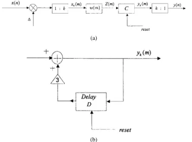
Fig. 1. Two-channel nonuniform-division maximally decimated filter bank system. (a) Analysis system. (b) Synthesis system.
sulting optimization problem. Section IV presents the method utilizing the WLS algorithm for obtaining a design with reconstruction response and filter stopband response. In Section V, the method in conjunction with a new filter structure for obtaining a design with 1, 0, and 1 coefficients from the continuous designs is proposed. Several simulation examples are provided in Section VI for illustration. Finally, we conclude this paper in Section VII.
II. TWO-CHANNEL NONUNIFORM-DIVISION FIR FILTER BANKS
Consider the two-channel NDF bank with the architecture given in [7], which is shown in Fig. 1. The analysis lowpass
and highpass filters are designated by and ,
respectively, whereas the synthesis lowpass and highpass filters are designated by and , respectively. and are two lowpass filters responsible for achieving aliasing-free operation during the rational decimation and interpolation. It can be shown that using the modulations of
multiplying in a highpass subband channel leads
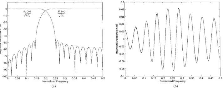
to the favorable result that can be a lowpass filter with real coefficients. The desired magnitude responses for
the analysis filters and with passband widths
equal to and , respectively are shown in Fig. 2,
where and denote the related band-edge
frequencies satisfying
Assume that the associated magnitude responses are set
to for and for
and for
and for respectively. Further,
assume that and have zero stopband response.
As shown in the Appendix, the input/output relationship of the
Fig. 2. Desired magnitude specifications for the analysis filters.
NDF bank in the frequency domain is given by [11]
(1)
where and are the resulting group delays of the
upper and lower channels, respectively.
Substituting and into (1) yields (2) where (3) l (4) (5) The first term of (2) represents the response of a linear
shift-invariant system with input , whereas the other
two terms represent the resulting aliasing distortion. Therefore, perfect reconstruction requires the following conditions.
PR 1: The magnitude of must be equal to 1,
i.e., , for all
PR 2: The magnitude of must be zero, i.e., , for all
PR 3: The magnitude of must be zero, i.e., , for all
We note from (3) that must be a either case 1 or case 2 LP FIR filter, whereas must be a case 4 LP FIR filter, as shown in [9], to ensure the PR 1 condition. Let and have filter lengths equal to and , respectively.
Then, can be expressed as [9]
where
for case 1
for case 2
and denotes the impulse response of Similarly,
we can express as [9]
(7) where
and denotes the impulse response of
Substi-tuting (6) and (7) into (3) yields
(8)
Let and Assuming
, we can neglect the LP term of (8) and express as
(9) Next, substituting (6) and (7) into (4) and (5), we can obtain
(10) and
(11) respectively, where it is also assumed that the related group delay difference between the lowpass and highpass subband channels is equalized.
Following (9)–(11), we can reformulate the conditions re-quired for perfect reconstruction as
for for for
for
(12)
Equation (12) reveals that the conditions for perfect
recon-struction can be met only when and have infinite
filter length. Therefore, the design problem of the two-channel
NDF banks of Fig. 1 is finding such and with
finite filter length that the conditions listed in (12) can be approximately met in some optimal sense.
III. OPTIMAL DESIGN OF TWO-CHANNEL
NDF BANKS IN THE SENSE
A. Problem Formulation Using an Approximation Scheme According to the conditions listed in (12), the overall error function to be minimized in the sense can be expressed as
(13) where is the squared reconstruction error given by
(14) and denote the squared stopband errors of and
, respectively. They are given by and
(15) where denotes the squared error related to the fourth condition of (12) and is given by
(16)
The parameters represent the relative weights
between and From (13), we note that the
overall error function is a function of the fourth degree in the filter coefficients. Therefore, directly minimizing leads to a highly nonlinear optimization problem. Although many well-developed nonlinear programming algorithms can be utilized to solve (13), to obtain satisfactory design results in several iterations is not an easy task.
Based on a linearization scheme, we present a method to efficiently solve the design problem of (13). During the optimization process for finding the optimal filter coefficients,
let and be the filter coefficients of and
, respectively, at the th iteration. An approximation for is defined as
(17)
where and denote the magnitude responses
corresponding to and , respectively. Accordingly, we have the following approximation for the overall error function:
(18) Note that of (18) is a quadratic function of the filter
coefficients if and are two known functions
B. The Proposed Design Method Let
be a grid of equidistant frequencies distributed in the range
of to for evaluating the magnitude response
of the NDF bank and the related error functions defined as above. Assume that is a case 2 LP FIR filter. We define
the following matrices. is a matrix with the
th element given by
(19)
is a matrix with the th element given by
(20)
is an matrix with the th element given by
(21)
is a matrix with the th element
given by
(22)
is a matrix with the th element
given by
(23)
is an matrix with the th element given by
(24)
is a matrix with the th element
given by
(25)
is a matrix with the th element
given by
(26)
Moreover, let and be two vectors containing the indepen-dent filter coefficients as
and
(27) where the superscript denotes the transpose operation.
Utilizing the above matrix notations, the overall design problem according to (18) can be approximately reformulated in matrix form as
(28) where
diag
diag , and is
a column vector with size and all entries equal to one. Therefore, finding the filter coefficient vectors and that minimize (28) is equivalent to solving the following linear equations:
or
(29) where
(30) After obtaining the coefficient vectors and , we update the
coefficients of and at the th iteration as
for
for (31)
Our simulations show that the overall error function given by (28) decreases as the iteration process proceeds when using (31) to update the designed filter coefficients. It is appropriate to terminate the design process if the following criterion is satisfied:
(32) where denotes the value of at the th iteration with filter coefficients and is a preset small positive real number. To initiate the design process, it is appropriate to set the initial filter coefficients and to the least-squares results, which optimally approximate the desired
magnitude specifications shown in Fig. 2. That is, the initial filter coefficient vectors and are given by the closed-form solutions
(33) Here, we summarize the proposed method by presenting the following design procedure.
Design Procedure 1:
Step 1) Specify the design parameters: filter lengths
and the bandedge frequencies and the
relative weights and and the value of
Set the iteration number
Step 2) Obtain the initial filter coefficient vectors and using (33). Then, compute the corresponding initial
magnitude responses and
Step 3) Compute the coefficients and by
solv-ing the linear equations of (29).
Step 4) Compute the resulting filter coefficients at the th iteration using the updating formulas given by (31).
Step 5) Compute the corresponding overall error function If the stopping criterion shown by (32) is satisfied, terminate the design process. Otherwise,
set , and go to Step 3.
IV. OPTIMAL DESIGN OF TWO-CHANNEL
NDF BANKS WITH RECONSTRUCTION
RESPONSE AND STOPBAND RESPONSE
A. Problem Formulation Using a WLS Algorithm and an Approximation Scheme
In order to achieve the design with equiripple reconstruction error, the associated overall error function can be formulated based on the WLS algorithm of [8]
(34) where denotes the frequency response weighting func-tion. Equation (34) reveals that the design problem becomes the minimization of the reconstruction error in the weighted squares (WLS) sense and the stopband error in the least-squares sense. To obtain the design result with equiripple reconstruction error, the weighting function must be appropriately chosen. The WLS algorithm presented in [8] provides a systematic approach for finding the suitable
Utilizing the result of (17) obtained from approximation, we reformulate the overall error function of (34) as
(35)
B. The Proposed Design Method
Using the matrices given by (19)–(27), we can express (35) in matrix form as
(36) where represents a diagonal matrix containing the weight
values of evaluated on the dense grid
, i.e., Again, (36) is a quadratic function of and Hence, finding the filter coefficients that minimize (36) is equivalent to solving the following linear equations:
or
(37) where
(38) After obtaining the coefficient vectors and , we update the filter coefficients by using the updating formulas of (31) at the th iteration. To achieve the design with equiripple reconstruction error, the WLS algorithm presented in [8] is utilized for adjusting during the design process. The following procedure summarizes the proposed design method.
Design Procedure 2:
Step 1) Specify the design parameters: filter lengths
and the bandedge frequencies and the
relative weights and and the value of
Set the iteration number
Step 2) Obtain the initial filter coefficient vectors and using (33). Then, compute the corresponding
initial magnitude responses and
Moreover, set the initial weighting matrix to the identity matrix.
Step 3) Compute the coefficients and by
solv-ing the linear equations of (37).
Step 4) Compute the resulting filter coefficients at the th iteration using the updating formulas given by (31).
Step 5) Compute the corresponding overall error function If the stopping criterion shown by (32) is satisfied, go to Step 6). Otherwise, set , and go to Step 3).
Step 6) Find Max(V) and Min(V), which are the maximum
and minimum of over the extremal
(a)
(b)
Fig. 3. Proposed new filter structure. (b) Function block C.
construction of [8]. If
Max Min
Max (39)
is satisfied, then terminate the design process. Oth-erwise, go to Step 7).
Step 7) Adjust according to the WLS algorithm of [8] as follows.
7.1) Construct the envelop function of
7.2) Compute the updating function according to (40)
7.3) Update the frequency response weighting function by performing
Then, we update the corresponding weighting
ma-trix , set , and go to Step 3).
V. OPTIMAL DESIGN OFTWO-CHANNEL NDF BANKSWITHCOEFFICIENTS 1, 0,AND 1
A. The Proposed Filter Structure
Consider the new filter structure shown by Fig. 3 for real-izing the LP analysis and synthesis filters. The input sequence is first multiplied by to adjust the range of The purpose of oversampling by is to keep the error due to the operation similar to the delta modulation, as shown by the function block at an acceptable level. The impulse response has a finite number of samples with values restricted to 1, 0, and 1 only. The reset terminal receives a signal to clear the contents of the delay element of when
Let the impulse response of the filter structure be
with length will have length Setting
to an impulse sequence, we obtain
for (41)
and
(42) We note that imposing the reset operation in is equivalent to putting a constraint for , as shown by (42). Moreover, (41) and (42) can be rewritten as
(43) where denotes the largest integer not greater than The sum in (43) is obtained due to the fact that in , only the samples after the last reset have to be considered. Accordingly, the relationship between , which is equal to the impulse
response and , is given by
for (44)
Let for ; thus, we can rewrite (44) as
for (45)
Since has values restricted to 1, 0, and 1 only for , we note from (45) that satisfies the following inequalities:
(46)
For any integer within the range of
, it is easy to show that there exists a unique set of
such that the integer can be expressed as
(47)
B. Discrete Optimization Procedure
The procedure is basically a modification of that given in [10] and described as follows.
1) Constrained Optimization: Let
Assume that represents the continuous coefficient vector excluding the th coefficient , which is fixed at a discrete value, i.e.,
as
(48) Let be the vector of (48) that minimizes the overall error function of (18) when is fixed at a discrete value Let the difference between the optimal continuous value
and the discrete value of be
Based on the LMS algorithm of [10], we can obtain , where denotes the coefficient vector
, which is obtained from the Design Procedure 1 or Design Procedure 2, with
omitted. is an column vector
given by , where and are obtained from
the submatrices of of (30) or (38). Let be partitioned as
(49)
where and are the th row and the
th column of , respectively. Then
and (50)
Next, for fixed , we put Let be
the coefficient vector that minimizes (18) when and are fixed at discrete values. Assume that the differ-ence between the optimal continuous value and the
discrete value of the coefficient is
Similarly, we can obtain
, where represents the vector with
the coefficient omitted. We obtain by following
the same procedure as above with instead of This
process is repeated until all of the filter coefficients are chosen and fixed at discrete values. The required weighting function for finding the WLS design solution is adjusted based on the obtained discrete filter coefficients using the systematic adjusting approach of [8].
2) Tree Search Algorithm: The algorithm used for perform-ing the tree search is basically the same as that presented in [10]. However, some modifications are made to enhance the capability of the proposed design method. After obtaining the optimal continuous coefficient design from (29) or (37), we choose a coefficient and fix it at discrete values in the vicinity of An optimization problem must be solved for each of the discrete values of to find the corresponding Based on the , further optimization problems are produced when the second coefficient
is chosen and fixed at discrete values. Therefore, optimization problems must be solved when and take on discrete values. To keep the required computation load manageable, we select only of the optimization problems for further discretizing the remaining coefficients. The criterion for selecting the optimization problems is to choose the problems that provide the smallest values of the overall error function or the weighted peak reconstruction error. Next, each of the selected problems produces other optimization problems when the third coefficient is chosen to take on discrete values. The search process continues until all of the filter coefficients are discretized.
3) Filter Coefficient Selection: We present a criterion for dealing with the discrete coefficient constraint of (46). In general, the grid density decreases as the value of discrete coefficients increases. Thus, the effect of discretizing the small coefficients is more easily compensated by the remaining reoptimized coefficients. Hence, we discretize the coefficient with the largest relative sensitivity first at each tree stage. The relative sensitivity of a continuous coefficient is defined as
Relative Sensitivity of Max (51)
where is the th element of the vector
C. The Design Procedures
The following design procedure summarizes the optimal design with coefficients 1, 0, and 1 under the criterion of reconstruction response and filter stopband response. Design Procedure 3:
Step 1) Use the design method presented in Section III to find the optimal continuous coefficient vectors and
Step 2) Choose four powers-of-two values in the vicinity
of the maximum of as the
values for the step size
Step 3) For a given , perform the discrete optimiza-tion procedure described in Secoptimiza-tion V-B to find the corresponding discrete coefficients
Step 4) Compute the error function of (28)
correspond-ing to , and adjust the matrices and
Then, recompute the new optimal continuous coefficient vector from (29).
Step 5) Repeat Steps 3) and 4) until the overall error function cannot be further reduced.
Step 6) Select the that makes the overall error function smallest among the four powers-of-two values for Find the corresponding by utilizing the relationship given by (45).
The optimal design with coefficients 1, 0, and 1 under the criterion of reconstruction response and filter stopband response is summarized as the following design procedure:
Design Procedure 4:
Step 1) Use the design method presented in Section IV to find the optimal continuous coefficient vectors and
Step 2) Choose four powers-of-two values in the vicinity
of the maximum of as the
values for the step size
Step 3) For a given , perform the discrete optimiza-tion procedure described in Secoptimiza-tion V-B to find the corresponding discrete coefficients
Step 4) Compute the reconstruction error function
corresponding to , and
adjust the matrices and using the WLS
algorithm of [8]. Then, recompute the new optimal continuous coefficient vector from (37). Step 5) Repeat Steps 3) and 4) until the peak reconstruction
error cannot be further reduced.
Step 6) Select the that makes the overall error function smallest among the four powers-of-two values for Find the corresponding by utilizing the relationship given by (45).
VI. SIMULATION EXAMPLES
In this section, we present several simulation examples of designing two-channel NDF banks with LP FIR filters having coefficients of 1, 0, and 1 only for illustration. These designs are performed on a personal computer with Pentium CPU using MATLAB programming language. For all design examples, the number of frequency grid points used is
set to 8 Moreover, the ripple ratio for the
design problem shown by (24) is set to 0.25. The values of and used for terminating the design process are set to 10 and 10 , respectively. The number for discretizing filter coefficients and the for oversampling are set to 3 and 10, respectively. The performance for each of the designed filter banks is evaluated in terms of the peak reconstruction error (PRE) in decibels, the normalized peak stopband ripple (NPSR) in decibels, and the stopband ripple energies (SRE)
of the designed and They are defined as
PRE for NPSR for SRE NPSR for and SRE (52)
Example 1: We use the design specifications shown by Table I and Design Procedure 3. Table II shows the significant design results for both of continuous and discrete coeffi-cients. The resulting step size and discrete coefficients
TABLE I
DESIGNSPECIFICATIONS FOREXAMPLES1AND 2
TABLE II
SIGNIFICANTDESIGNRESULTS FOREXAMPLE1
of the designed analysis filters are listed in Table III. Fig. 4 plots the corresponding magnitude responses in decibels of
and and the overall magnitude
response in decibels of the designed NDF banks with 1, 0, and 1 coefficients (dashed-line) and with the optimal continuous coefficients (solid-line), respectively. We note that the satisfactory performances of the designed NDF banks with the optimal continuous coefficients and coefficients of 1, 0, and 1 only are very close.
Example 2: The design specifications shown by Table I and Design Procedure 4 are used for this design. Table IV lists the significant design results for both of continuous and discrete coefficients. Table V lists the resulting step size and discrete coefficients of the designed analysis filters. Fig. 5 depicts the corresponding magnitude responses in decibels of
and and , in decibels, of the
designed NDF banks with 1, 0, and 1 coefficients (dashed-line) and with the optimal continuous coefficients (solid-(dashed-line), respectively. Again, we observe that the designed NDF banks show very close satisfactory performances.
VII. CONCLUSION
This paper has presented a technique for the optimal design of two-channel nonuniform-division filter (NDF) banks with linear-phase FIR filters having 1, 0, and 1 coefficients only. First, we formulate the design problem with continuous coefficients for each of two optimal criteria, namely, least-squares reconstruction response and filter stopband response and equiripple reconstruction response and least-squares filter stopband response. The WLS algorithm of [8] has been utilized to achieve the design of equiripple reconstruction
(a) (b) Fig. 4. Magnitude responses for Example 1. (a)H0(!)=pLL0andH1(!)=pLL1: (b) T (!):
TABLE III
(a) ANALYSISFILTERCOEFFICIENTS FOR THECONTINUOUS DESIGN OFEXAMPLE1. (b) ANALYSISFILTERCOEFFICIENTS FOR THEDESIGN WITHCOEFFICIENTS01, 0, +1OFEXAMPLE1
(a)
(b)
TABLE IV
SIGNIFICANTDESIGNRESULTS FOREXAMPLE2
behavior. In conjunction with a new filter structure for realiz-ing the analysis filters, an efficient method to obtain an optimal design with coefficients restricted to 1, 0, and 1 only has been presented. The effectiveness of the proposed technique has been demonstrated by several design examples.
APPENDIX
Here, we derive the input/output relationship given by (1) of the NDF bank shown in Fig. 1. From the architecture of Fig. 1, we have
(53) After interpolating and filtering, we obtain
and
(54) Performing decimation yields
(a) (b) Fig. 5. Magnitude responses for Example 2. (a)H0(!)=pLL0andH1(!)=pLL1: (b) T (!):
TABLE V
(a) ANALYSISFILTERCOEFFICIENTS FOR THECONTINUOUSDESIGN OFEXAMPLE2. (b) ANALYSISFILTERCOEFFICIENTS FOR THEDESIGN WITHCOEFFICIENTS01, 0, +1OFEXAMPLE2
(a)
(b)
In the synthesis system, after interpolating and filtering, we have
(56) Performing the decimation provides
(57)
Next, multiplying by , performing filtering by
, and taking the summation yields
(58)
Utilizing the assumption that for
and for ,
respectively, and the assumption that and have
zero stopband response, (58) becomes
(59) where and denote the resulting group delays of the upper and lower channels, respectively. Finally, (1) can be obtained by substituting into (59).
REFERENCES
[1] R. E. Crochiere, “Digital signal processor: Sub-band coding,” Bell Syst.
Tech. J., vol. 60, pp. 1633–1653, 1981.
[2] M. G. Bellanger and J. L. Daguet, “TDM-FDM transmultiplexer: Digital polyphase and FFT,” IEEE Trans. Commun., vol. COMM-22, pp. 1199–1204, Sept. 1974.
[3] P. Vary and U. Heute, “A short-time spectrum analyzer with polyphase network and DFT,” Signal Process., vol. 2, pp. 55–65, 1980. [4] J. W. Woods and S. D. O’Neil, “Subband coding of images,”
IEEE Trans. Acoust., Speech, Signal Processing, vol. ASSP-34, pp.
1278–1288, Oct. 1986.
[5] K. Nayebi, T. P. Barnwell, and M. J. T. Smith, “Nonuniform filter banks: A reconstruction and design theory,” IEEE Trans. Signal Processing, vol. 41, pp. 1114–1127, Mar. 1993.
[6] S. Wada, “Design of nonuniform division multirate FIR filter banks,”
IEEE Trans. Circuits Syst. II, vol. 42, pp. 115–121, Feb. 1995.
[7] J.-H. Lee and S.-C. Huang, “Design of two-channel nonuniform- di-vision maximally decimated filter banks usingL1criteria,” Proc. Inst.
Elect. Eng, Vision, Image Signal Process., vol. 143, no. 2, pp. 79–83,
Apr. 1996.
[8] Y.-C. Lim, J.-H. Lee, C.-K. Chen, and R. H. Yang, “A weighted least-squares algorithm for quasiequiripple FIR and IIR digital filter design,”
IEEE Trans. Signal Processing, vol. 40, pp. 551–558, Mar. 1992.
[9] L. R. Rabiner and B. Gold, Theory and Application of Digital Signal
Processing. Englewood Cliffs, NJ: Prentice-Hall, 1975.
[10] Y. C. Lim and S. R. Parker, “Discrete coefficient FIR digital filter design based on an LMS criteria,” IEEE Trans. Circuits Syst., vol. CAS-30, pp. 723–739, Oct. 1983.
[11] B. Liu and L. T. Bruton, “The design of nonuniform-band maximally decimated filter banks,” Proc. IEEE Int. Symp. Circuits Syst., Chicago, IL, May 1993, pp. 375–378.
Ju-Hong Lee (M’86) was born in I-Lan, Taiwan, R.O.C., on December 7, 1952. He received the B.S. degree from the National Cheng-Kung University, Tainan, Taiwan, in 1975, the M.S. degree from the National Taiwan University, Taipei, in 1977, and the Ph.D. degree from Rensselaer Polytechnic Institute (RPI), Troy, NY, in 1984, all in electrical engineering.
From September 1980 to July 1984, he was a Research Assistant and was involved in research on multidimensional recursive digital filtering with the Department of Electrical, Computer, and Systems Engineering, RPI. From August 1984 to July 1986, he was a Visiting Associate Professor and, later, in August 1986, became an Associate Professor in the Department of Electrical Engineering, National Taiwan University. Since August 1989, he has been a Professor at the same university. He was appointed Visiting Professor with the Department of Computer Science and Electrical Engineering, University of Maryland, Baltimore, during a sabbatical leave in 1996. His current research interests include multidimensional digital signal processing, image processing, detection and estimation theory, analysis and processing of joint vibration signals for the diagnosis of cartilage pathology, and adaptive signal processing and its applications in communications.
Dr. Lee received Outstanding Research Awards from the National Science Council in 1988, 1989, and 1991 to 1994.
Ding-Chiang Tang was born in Chang-Hua, Tai-wan, R.O.C., on August 20, 1974. He received the B.S. and M.S. degrees from the National Taiwan University, Taipei, in 1996 and 1998, respectively, all in electrical engineering.
His current research interests include digital sig-nal processing and its applications.