國
立
交
通
大
學
資訊科學與工程研究所
碩
士
論
文
基於 FMO 及收斂性動態預測的不對等保護方法
An Unequal Error Protection Scheme based on FMO and
Converged Motion Estimation
研 究 生:石仲禹
指導教授:蔡文錦 教授
基 於 FMO 及 收 斂 性 動 態 預 測 的 不 對 等 保 護 方 法
An Unequal Error Protection based on FMO and Converged Motion
Estimation
研 究 生:石仲禹 Student:Jhong-Yu Shih
指導教授:蔡文錦 Advisor:Wen-Jiin Tsai
國 立 交 通 大 學
資 訊 科 學 與 工 程 研 究 所
碩 士 論 文
A ThesisSubmitted to Institute of Computer Science and Engineering College of Computer Science
National Chiao Tung University in partial Fulfillment of the Requirements
for the Degree of Master
in
Computer Science
June 2007
Hsinchu, Taiwan, Republic of China
摘要
在這篇論文裡,我們提出一個在多錯誤的網路環境下傳輸影像的 UEP (Unequal Error Protection) 系統。我們使用含在 H.264 標準裡的工具 ─ FMO (Flexible Macroblock Ordering) , 並 提 出 了 失 真 預 測 方 法 來 對 所 有 的 Macroblocks 分類。為了讓錯誤隱藏更有效率,使用基於 Dispersed 模式所衍生 出的新模式搭配 K-mean 分群演算法來分配 Macroblock 到各個 Slice groups。 最後,我們提出收斂性動態預測來進一步加強所提出的 UEP 系統。實驗結果顯示 我們的方法的確完善地保護重要的資料,且收斂性動態預測更加強了效果。
Abstract
In this thesis, we present an unequal error protection (UEP) scheme for video transmission over error-prone networks. The Flexible Macroblock Ordering (FMO), included in H.264 standard, is used to accommodate different slice groups with different importance in a frame. We propose a distortion estimation scheme to define the importance of macroblocks and then assign macroblocks to slice groups based on a variation of the dispersed FMO mode and k-means clustering algorithm. Finally, a Converged Motion Estimation (CME) is proposed to further improve our proposed UEP scheme. The idea behind the proposed CME is to make important macroblocks concentrated on few only, so that the use of redundancy for error protection will be more efficient. The experimental results show that the important data is well protected using our proposed UEP scheme, and CME further improves the performance.
Keywords: Unequal error protection, Flexible macroblock ordering, Converged motion estimation
Contents
Abstract . . .
1 Introduction . . .
2 Related Works . . .
2.1 Macroblock Classification Scheme . . . 2.2 Macroblock Assignment . . . 2.3 Channel Rate Allocation . . .
3 Motivation . . .
4 Proposed Unequal Error Protection Method . . .
4.1 Macroblock Classification Scheme . . . 4.2 Macroblock Assignment . . .
4.2.1 Dispersed mode. . . 4.2.2 K-means clustering. . . 4.3 Channel Rate Allocation . . .
5 Converged Motion Estimation. . .
6 Experimental Results . . . 7 Conclusion . . . Reference . . . 3 9 17 17 18 19 20 21 22 24 25 26 28 31 35 41 42
List of Figures
Figure 1.1 A typical video communication system
Figure 1.2 Unequal Error Protection
Figure 1.3 Reed-Solomon Code
Figure 1.4 Different gray colors denote the degree of importance
Figure 1.5 Repartition of the error protection redundancy over the GOPs
Figure 1.6 Unequal error protection for the scalable units
Figure 1.7 Reordering
Figure 1.8 Macroblock classification
Figure 1.9 ESI mode
Figure 4.1 Flowchart
Figure 4.2 Connected MBs would cause the error concealment ineffective
Figure 4.3 Fixed size v.s. Variable size slices
Figure 4.4 Standard FMO mode
Figure 4.5 Macroblock assignment based on dispersed mode
Figure 4.6 An example of macroblock assignment with fixed size and variable
size slices
Figure 4.7 An example of channel rate allocation for frames
Figure 4.8 An example of channel rate allocation for slices
Figure 5.1 Flowchart
Figure 5.2 A sketch map of converged motion estimation
Figure 5.3 An example of converged motion estimation
Figure 6.1 The PSNR when packet loss rate reach (a) 10% (b) 20% in Forman
9 10 11 12 12 13 14 15 16 21 24 24 25 26 27 29 30 31 32 33 36
Figure 6.2 The PSNR when packet loss rate reach (a) 10% (b) 20% in
Coastguard
Figure 6.3 The PSNR when packet loss rate reach (a) 10% (b) 20% in Stefan
Figure 6.4 The average PSNR when packet loss rate equal to 5% ~ 25% in
video stream
37
38 39
List of Tables
Table 4.1 The symbol table for distortion estimation
Chapter 1
Introduction
In the transmission of video in error-prone network, the packet loss is a key problem. The video is very sensitive to transmission error after being compressed. Associating the compressed bit-stream with forward error correction (FEC) for both error detection and error correction can overcome the problem but more network bandwidth is needed. Video Source Encoding Packetizing & Channel Encoding Network Depacketizing & Channel Decoding Video Source Decoding
Figure 1.1 A typical video communication system [2]
A typical video communication system [2] involves many steps, as shown in figure 1.1. The video encoder first compresses the video source into a bit-stream for reducing the data rate. Then, the compressed bit-stream is assigned FEC segmented
into packets. While transporting packets, the Channel decoder receives the packets and corrects the error if packet is lost or damaged. Finally, the video decoder decodes the bit-stream to a reconstruct video.
In video source, some data are more important than others. For example, the picture headers are much more important than the block data because, once it is lost, the entire picture can not be constructed well. These important data should be protected so that they can be delivered with a much lower error rate as shown in figure 1.2 This is the concept of well-known Unequal Error Protection (UEP). An effective UEP scheme ponders the criteria of importance from many kinds of point of view and takes advantage of the different sensitivities of the output bit-stream of video encoder.
Picture headers
Other data
Protection
Protection
Figure 1.2 Unequal Error Protection
raditionally, Reed-Solomon (RS) Codes [13] are used as FEC and are widely applied in digital co
T
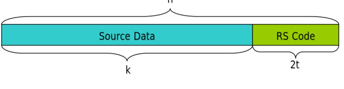
mmunications and storage, such as DVD, wireless communications, and digital television. A Reed-Solomon code is specified as RS(n, k) with m-bit symbols. This meant that the total size is n symbols of m bits each, of which k symbols are the source data and n-k symbols are redundancy. The maximize error correcting capability is t symbols as shown in figure 1.3.
Source Data RS Code n
k 2t
Figure 1.3 Reed-Solomon Code
For example, a RS(255, 247) code with 8-bit symbols. Each codeword contain 255
bytes, of which 247 bytes are source data and 8 bytes are parity. In this case, we have 2t = n - k = 255 – 247 = 8, so t = 4, meaning that the error
correcting capability is 4 bytes. Thus, the Reed-Solomon decoder can correct any 4 symbols (4 bytes) in the codeword.
In a video transmission system, source and channel distortion would degrade the quality of the video. Such quality degradation can be reduced greatly if we could estimate the source and channel distortion correctly. Distortion estimation [7, 14, 17] is a domain researched widely and is the basic of Unequal error protection (UEP). Here we classify the general UEP methods into four categories as follows.
(a) Frame-based
In a Group of Picture (GOP), it is obviously that I frames are more important than P frames, and P frames are more important than B frames. If the I frame lost too many macroblocks, not only the I frame could not be concealed well, but also a lot of error propagation would brought. With the same reason, the front P frame are important than the rear P frame in the same GOP because the former would bring more error propagation than the latter. In [3, 11], frame-based unequal error protection schemes are proposed. As shown in figure 1.4 [11], the darker means the
more important, and therefore the more protection will be assigned. In figure 1.5 [3], the concept of frame-based equal error protection (EEP) is shown in figure 1.4 (a), and the unequal error protection (UEP) is shown in figure 1.4 (b).
Figure 1.4 Different gray colors denote the degree of importance [11]
Figure 1.5 Repartition of the error protection redundancy over the GOPs:
(b) Scalability Layer based
The scalable video coding (SVC) in H.264 provides a full scalability including spatial, temporal and signal-to-noise ratio (SNR) scalability. A SVC stream may consist of many layers with one base layer, and multiple enhancement layers. The base layer which provides basic video quality is much more important than enhancement layers. The higher enhancement layers which depend on the lower enhancement layers are less important. In [2, 15], scalability layer based UEP methods are proposed, which allocate different channel rate for different layers according their importance as shown in figure 1.6.
Figure 1.6 Unequal error protection for the scalable units [15]
(c) Data Partitioning based
There are three different partition types used in data partition mode of H.264: ¾ Partition A: Header information.
¾ Partition B: Intra Partition. ¾ Partition C: Inter Partition.
Among them, Partition A is the most important and Partition C is the least important. Although Partition C is less important than Partition B, the volume of bit stream in Partition C is far more than that in Partition B. Different inter macroblocks included in Partition C may have different importance respectively, but there is no further partition in C type in current H.264 standard, which means the error protection degree for all the C type are the same. In [10], an unequal error protection method based on data partitioning for H.264 [5] are proposed. Their partition method subdivides Partition C into several subtypes for different inter-coded macroblocks according to the effect to error propagation.
In H.264, data partition is a good tool to partition the bit stream into several segments, but it is not available in other standards, such as H.263. A UEP framework which applies reordering process is proposed [6] for H.263. As shown in figure 1.7. after H.263 encoder encodes the video source, the Ordering Module will order the bit stream according to the importance, and the Re-ordering Module at the decoder will reorder the bit stream back to original bit stream encoded by H.263 Encoder.
(d) Slice-based
Flexible Macroblock Ordering (FMO) is a tool included in the H.264 standard to partition the entire frame into many slice groups. Because the slice groups will be transported separately, we can assign unequal error protection to these slice groups according to their importance, we call slice groups “slices” below. In [9, 12], data classification schemes with the H.264 explicit FMO mode are proposed as shown in figure 1.8. They use distortion estimation to estimation which macroblock would produce more distortion than others, and let those macroblocks be in the same slice with more protection.
Figure 1.8 Macroblock classification (a) without FMO, (b) dispersed map, (c) original
Generally, error concealment is well performed in dispersed FMO mode. In [1], a new FMO mode is proposed. They combined dispersed FMO mode and box-out FMO mode, named Explicit Spiral-Interleaved (ESI) FMO mode, as shown in figure 1.9.
Figure 1.9 ESI mode (a) combination of the dispersed mode and box-out mode
(b) dispersed mode (c) box-out mode [1]
In the thesis, a slice-based UEP method is proposed, which provides a new variation of FMO pattern, based on dispersed mode and k-means clustering algorithm, to support unequal error protection. Besides we also propose a new motion estimation technique (called Converged Motion Estimation), which tries to make the macroblocks be referenced unequally as much as possible. That is, few macroblocks belonging to important slices are referenced with very high frequency; while others (belonging to less important slices) with low frequency. The experimental results show that such kind of unbalanced reference will significantly Improve the efficiency of UEP. The rest of this thesis is organized as follows. Chapter 2 gives the introduction to related works of UEP, and chapter 3 gives our motivation. Our proposed scheme is discussed in chapter 4 and chapter 5, and the experimental results are shown in chapter 6. The conclusion is given in the last chapter.
Chapter 2
Related Works
In chapter 1, we have introduced four categories of UEP. Both frame based scheme and data partition scheme can not provide UEP at fine granular level, such as macroblocks, and scalability layers scheme must be used in scalable stream, thus we chosen slice based scheme for our proposed UEP method to be based upon. In this chapter, we introduce previous slice-based UEP framework using FMO.
2.1 Macroblock Classification Scheme
For slice-based UEP, the importance of each macroblock will be estimated first. Some researches determined the importance of a macroblock according to its location [13]. The macroblocks located in the center of the frame are more important that those located on the frame boundaries. Region of Interest (ROI) based UEP [1, 7] emphasizes the regions which human favors, therefore, macroblocks located in the foreground regions are more important. In [15], they considered the three parameters: (1) the macroblock’s number of bits, (2) the distortion of the coded macroblock with respect to the original picture, and (3) the distortion of the macroblock if it is lost and concealed only using the surrounding macroblocks. In (1), the fewer number of bits a macroblock requires, the more important it will be, assume that there are two macroblocks MB1 and MB2 requiring R1 and R2 bits (R1 < R2) for transmission,
and one of them should be selected for better error protection. In (2), with the same reason, if the distortion of the coded macroblock is greater, the residual data will be also greater, thus the more number of bits will be needed. In (3), if the error for an individual macroblock provides a good replacement for it (with low distortion,) it will have an inferior importance. In [5], they considered the reconstructed distortion (that is, quantization error) only.
2.2 Macroblock Assignment
For the slice-based UEP, once the importance of each macroblock is determined, the next step is to assign each macroblock to difference slice according to the importance. In [15], assume two slices are used with slice 1 more important than slice 2. The MB with highest impact factor will be moved to slice 1. However, since this action will influence the neighboring macroblocks of the just moved macroblock, the importance of the neighboring macroblocks must be updated accordingly. The recalculation of macroblock importance and macroblock assignment are performed repeatedly till an optimal solution is found. This approach needs a great deal of computation complexity. In [5], they used three slices and compared the impact factors with two thresholds, Th and Tl, as follows.
¾ If impact factor >= Th : high importance slice
¾ If impact factor < Th and >= Tl : medium importance slice ¾ If impact factor < Tl : low importance slice
2.3 Channel Rate Allocation
Once the FMO table is determined, which means that what slice each macroblock is belonged to has been decided, the encoding process can encode bit stream according to the FMO table now and the encoded bit stream will consist of separate slices. The issue then would be how to distribute the available FEC among these slices with different importance. In [9], the expected length of error propagation (ELEP) is used to describe the effect of packet loss on the decoded video quality in order to achieve optimal FEC assignment. Initially, each slice has the same number of FEC packets, and then processes a while loop with different number of FEC packets until the minimal distortion calculated using ELEP is achieved. Finally, the number of FEC packets is how much protection we will assign.
Chapter 3
Motivation
For slice-based UEP, macroblock assignment which determines the slices that each macroblock should belong to is the most important part. Some researches simply sorting the macroblocks according to their importance; while some others exhaustedly calculate all the possible combinations of assignment to find the optimal allocation (with minimum predicted distortion). In this thesis, we want to finish the macroblock assignment with a simple and fast flow to achieve good performance. Besides that general schemes passively determine the importance of each macroblock for macroblock classification according to the encoding result. We want to adopt an active way to converge important macroblocks such that highly important macroblocks are fewer and more concentrated. Protecting such highly-concentrated important macroblocks with more redundancy would make UEP work more effectively.
Chapter 4
Proposed UEP Method
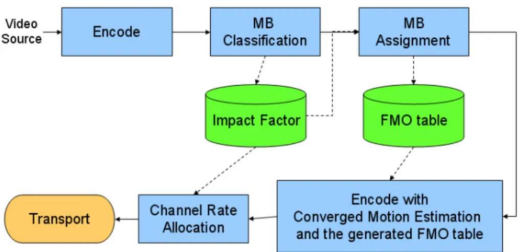
In the chapter, we describe our proposed UEP method in detail. In figure 4.1, the source encoder encodes the bit stream at first, after encoding, the MB Classification module will calculate all impact factors of all MBs. After getting the impact factors, the MB Assignment module will assign all MBs into some slices according to the impact factors and generate a Flexible Macroblock Ordering (FMO) table. Then, the source encoder uses the FMO table as input to encode with converged motion estimation (CME), CME would improve the efficiency of the UEP scheme. Finally, Channel Rate Allocation module uses the impact factors generated by MB Classification module to allocate the channel rates for assigning Reed-Solomon codes and transports the compressed video with FEC.
4.1 Macroblock Classification Scheme
In a frame, different macroblocks have different importance. For the macroblocks which will cause a great distortion if they were lost, we will regard them as more important and will protect macroblocks like these more than others. In our classification scheme, we introduce an ‘Impact Factor’ (IF) for each macroblock to represent its importance. The impact factor is the distortion we estimated.
To measure the impact factor of a macroblock, three distortions are considered: coding distortion Dc, concealment distortion De, and reconstruction distortion Dc’. The coding distortion Dc mainly comes from quantization step during encoding process. De is the distortion incurred by recovering the block being considered using the concealment method assumed by the encoder. Dc’ is distortion which is different from Dc in that it includes the incurred distortion due to prediction from already concealed blocks in the reference frame.
Table 4.1 The symbol table for distortion estimation
IF(MBi) Impact factor of MBi
p
Packet loss rate
Dc
Distortion of the reconstructed MB
De
Distortion of the concealed MB
Dc’
Distortion of the reconstructed MB when the referred MB are lost
The processes of error concealment in intra coded macroblocks and inter coded macroblocks are not the same. The spatial error concealment is performed for intra coded macroblocks, and the temporal error concealment is performed for inter coded macroblocks, thus the distortion estimation is not the same for intra coded
macroblocks and inter coded macroblocks.
Let IF(MBi) denote the impact factor of the macroblock MBi, and p the packet loss rate during network transmission. The impact factor for an intra-coded macroblock and an inter-coded macroblock are defined, respectively, as follows. The symbols used are summarized in table 4.1.
(1)
Intra coded macroblock:
(
i)
(1
)
IF MB
= −
p Dc
⋅
+ ⋅
p De
There are two cases as follows: (a) Macroblock MBi is not lost:
The probability is (1 – p), and the distortion is Dc. (b) Macroblock MBi is lost:
The probability is p, and the distortion is De.
(2) Inter coded macroblock:
2 2
(
i)
(1
)
(1
)
'
(1
)
IF MB
= −
p
⋅
Dc
+ −
p
⋅ ⋅
p Dc
+ ⋅ −
p
p De
⋅
+
p
⋅
De
There are four cases as follows:
(a) Both Macroblock MBi and the referred macroblock are not lost: The probability is (1 – p) 2, and the distortion is Dc.
(b) Macroblock MBi is not lost but the referred macroblock is lost: The probability is (1 – p) p, and the distortion is Dc’.
(c) Macroblock MBi is lost but the referred macroblock is not lost: The probability is p (1 – p), and the distortion is De.
(d) Both Macroblock MBi and the referred macroblock are lost: The probability is p2, and the distortion is De.
4.2 Macroblock Assignment
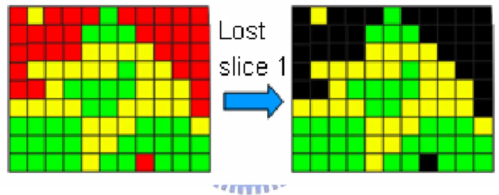
After getting impact factors of all macroblocks, we use the impact factors as input to assign all macroblocks to slices. The straightest method is to sort all the impact factors and then choose the one with the greatest impact factors to be assigned to the slice of high importance. But doing in this way make important macroblocks connected. If one slice was lost, the error concealment would be ineffective because the macroblocks around the lost macroblock are also lost as shown in figure 4.2. We will describe how to solve the problem in 4.2.1.
Figure 4.2 Connected MBs would cause the error concealment ineffective
Figure 4.3 Fixed size v.s. Variable size slices
The fixed-size slices and variable-size slices are two options for slice-based UEP. Fixed-size slices, while it is simple, it is not efficient for UEP. Consider the case in
figure 4.3 where there are 15 highly important macroblocks. With fixed-size slices, however, not only they would be assigned to slice 1, but also those macroblocks which are not really important would be assigned to it (total 33 MBs). More bit rate would be occupied because it needs more bit rate to protect slice 1 than other slices. We will describe how solve it in 4.2.2.
4.2.1 Dispersed mode
Dispersed mode is type 2 of slice group map in H.264 as shown in figure 4.4 (b). Error concealment is very effective in this mode because one slice, when it was lost, can be concealed from the other slice.
(a) (b)
Figure 4.4 Standard FMO mode (a) Raster scan FMO mode (b) Dispersed FMO
mode
Our macroblock assignment adopts the dispersed mode first with two slices (say slice1 and slice2) and then further split the two slices into more slices according to impact factor of macroblocks. In figure 4.5, assume we want to classify macroblocks into three different levels of importance, six slices will be used, where three slices comes from slice1 (all even macroblocks) and the other three comes from slice2 (all
odd macroblocks). It is obvious to notice that any macroblock belonging to slices 11, 12, and 13 must have adjacent macroblocks coming from slices 21, 22, as well as 23, and vice versa. Since no contiguous macroblocks will be assigned to the some slice, the error concealment could be effective. Regarding how to split a slice into more slices according to impact factor is described in 4.2.2.
Figure 4.5 Macroblock assignment based on dispersed mode
4.2.2 K-means clustering
This section presents a method to further split a slice into more slices according to the impact factors of MBs. Based on the idea that more FEC will be assigned to protect macroblocks with more importance, it is better to group the macroblocks with similar impact factor into the same slice, such that channel rate allocation (described in section 4.3) would be more efficient. Thus, we simply formulate the macroblock assignment problem as a clustering problem and k-means clustering algorithm [8] is used. The k-means follows a simple and easy procedure to classify a given data set
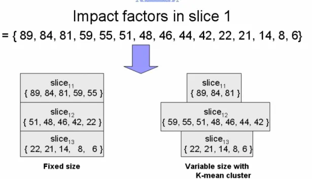
into a certain number of clusters (assume k clusters) with distance far away from each other as much as possible. Here we regard each macroblock as a single data point and the impact factor as its position in the coordinate axis for the algorithm. In figure 4.6, an example is given to show the result of applying k-means clustering on 15 macroblocks with impact factors ranging from 6 to 89. We see that the subset with the greatest impact factors is {89, 84, 81} using k-means clustering, but it would be {89, 84, 81, 59, 55} using fixed size slices. The 59 and 55 should not be in the slice11
because their impact factors are not so high as 89, 84, and 81. Therefore, we use K-mean to cluster the whole set of impact factors into several variable size subsets, and generate a FMO table according to the macroblock assignment.
Figure 4.6 An example of macroblock assignment with fixed size and variable size
slices
4.3 Channel Rate Allocation
FMO table. At first, we allocate the bit rate to each frame according to the importance of frames, and then allocate the bit rate of the frame to each slice according to the importance of slices. The importance of frame i is specified as:
(
)
(
j i i j MB Frame)
IF Frame
IF MB
∈=
∑
Then calculate the ratio of the impact factor of frame i to the sum of impact factors of all frames, the ratio is how much bit rate will we allocate. Assume A is the overall bit rate of GOP, S is the source bit rate of GOP, and then A - S is the redundancy bit rate of GOP for FEC. Therefore we can allocate the redundancy bit rate of frame in proportion as follows:
(
)
(
)
(
)
i i j i Frame GOPIF Frame
R
A S
IF Frame
∈=
×
−
∑
The De of intra macroblocks are usually greater than that of inter macroblocks, so I frames will be allocated more bit rate than P frame. In figure 4.7, we gave an example of channel rate allocation for frames. In Frame 1, because the ratio of its impact factor to the sum of impact factors of all frames is 31%, it can be allocated 31% of redundancy bit rate, 19.14Kbps.
Figure 4.7 An example of channel rate allocation for frames
Once the redundancy bit rates assigned to each frame is determined, how much redundancy bit rate to be assigned to each slice can be decided now. We allocate redundancy bit rates to each slice of each frame according to the importance of each slice. The importance of slice i, denoted by IF( Slice i ), is defined as the summation
of the impact factor of all the macroblocks belonging to slice i, as shown below.
(
)
(
j i i j MB Slice)
IF Slice
IF MB
∈=
∑
The redundancy bit rate allocated to slice i is determined by the ratio of the impact factor of slice i to the sum of impact factors of all slices in one frame. Rj is the redundancy bit rate for FEC used by frame j, therefore we can allocate this redundancy bit rate to each slice in frame j in proportional to their respective impact factor as follows:
(
)
(
)
i j i i j i Slice FrameIF Slice
r
R
IF Slice
∈=
×
∑
In figure 4.8, we gave an example of channel rate allocation for slices. For slice 1, we assume its impact factor to be 100, there the ratio of its impact factor to the sum of impact factors of all slices would be 33%. The redundancy bit rate of FEC allocated to it will be 19.14 Kbps x 33% = 6.38 Kbps.
Figure 4.8 An example of channel rate allocation for slices
Finally, assign Reed-Solomon codes to the bit stream according to the allocation of channel rates and then transport the bit stream.
Chapter 5
Converged Motion Estimation
Because we assign more protection to more important macroblocks, these macroblocks will be more robust against transmission error. To achieve a better performance of UEP, we should make important macroblocks concentrated on few blocks only. Based on this idea, we proposed a Converged Motion Estimation (CME), which will make these important macroblocks be referred by other macroblocks as many as possible. CME is performed during the encoding process after macroblock assignment, as shown in figure 5.1.
Figure 5.2 A sketch map of converged motion estimation
The proposed CME changes the general concept of motion estimation. Instead of choosing the macroblock with the least Mean Square Error (MSE) as reference for prediction, CME chooses the macroblock which is more important as reference if the increase in MSE is within an acceptable range. In figure 5.2, there are three candidates of reference macroblocks, with MSE being equal to 400, 450, and 1200, respectively. In the general process of motion estimation, the one with the least MSE, that is, the first candidate, will be chosen. Assume slice 2 is less robust (with less protection due to less important) compared to slice 1 against transmission error. For the first candidate which has 10% pixels located in slice 1, and 90% in slice 2, it might cause greater distortion due to many uncorrected errors, although it has a lower MSE. In this case, we prefer to choose the second candidate because it has 90% pixels located in slice 1 and 10% in slice 2 although it has a higher MSE.
To realize the concept above, we modify the definition of MSE by including penalty to the pixels that are referred to. It is specified as follows:
1
(
),
k
CME i i
i
MSE
MSE
n
c
where k is the slice number
=
=
+
∑
×
where
c
i is the per pixel penalty for slice i; andn
i is the number of pixels located in slice i for the reference macroblock being under considered. The pixels in the slices of low impact factor will be assigned with largec
i meaning that reference to these pixels will get a worse MSE; while the pixels in the slices of high impact factor will have smallc
i meaning that reference to them will get a better MSE.
(a) (b)
Figure 5.3 An example of converged motion estimation
Figure 5.3 shows an example, where the penalty of pixels in slice 1 is assigned as 1, and that of slice 2 is assigned as 2, meaning that the slice 1 is more important than
slice 2. In figure 5.3 (a), assume the original MSE is equal to 50, but with the proposed CME, it will be added with the penalty which is equal to 15 i.e.,
(2+2+2+2+2+2+1+1+1), therefore the MSECME is equal to 65. With the same reason,
MSECME in figure 5.3 (b) is 64 given the original MSE as 52. As a result in this
example, the reference block in figure 5.3 (b) has a smaller MSECME and thus will be
Chapter 6
Experimental Results
In the chapter, we compare the proposed method with the “Raster scan” and the “Dispersed” macroblock assignments, both of them are the FMO mode included in the standard. The parameters of our experimental environment are set as follows:
¾ Test sequence: Forman, Coastguard, Stefan ¾ Group of Picture (GOP): I P P P P …… ¾ GOP size: 15 frames
¾ Frame rate: 30 fps
¾ Frame format: QCIF (176 x 144 pixels) ¾ Slice number: 6 slices
¾ The per pixel penalty in CME
c
i = i, for i = 1 to 6, where the slice isnumbered in descending order of IF( Slice i )
¾ Packet size: 16 bytes
¾ Overall bit rate: 340Kbps (Forman), 360Kbps (Coastguard), 980Kbps (Stefan)
17 19 21 23 25 27 29 31 33 35 37 39 1 11 21 31 41 51 61 71 81 91 101 Frame Number PSNR Raster scan Dispersed Simple UEP
Proposed UEP method without CME Proposed UEP method with CME
(a) 11 13 15 17 19 21 23 25 27 29 1 11 21 31 41 51 61 71 81 91 101 Frame Number PS N R Raster scan Dispersed Simple UEP
Proposed UEP method without CME Proposed UEP method with CME
(b)
Figure 6.1 The PSNR when packet loss rate reach (a) 10% (b) 20% in Forman
The video sequences are encoded and decoded using JM 12.1, where the code of motion estimation is modify to support CME. In our experiments, “Raster scan” and “Dispersed” are Equal Error Protection (EEP) with the same overall bit rate. We add the “Simple UEP” which reorders the macroblocks according to their impact factors
18 20 22 24 26 28 30 32 34 36 1 11 21 31 41 51 61 71 81 91 101 Frame Number PS N R Raster scan Dispersed Simple UEP
Proposed UEP method without CME Proposed UEP method with CME
(a) 11 13 15 17 19 21 23 25 27 29 31 33 1 11 21 31 41 51 61 71 81 91 101 Frame Number PS N R Raster scan Dispersed Simple UEP
Proposed UEP method without CME Proposed UEP method with CME
(b)
Figure 6.2 The PSNR when packet loss rate reach (a) 10% (b) 20% in Coastguard
(IF) and then sequentially assign to 6 slices of equal size in order to test the effect of our macroblock assignments scheme. To test the effect of CME, we compare “Proposed UEP method without CME” and “Proposed UEP method with CME”. The measured average PSNR results of Forman, Coastguard, and Stefan with packet loss
13 15 17 19 21 23 25 27 29 31 33 1 11 21 31 41 51 61 71 81 Frame Number PS N R Raster scan Dispersed Simple UEP
Proposed UEP method without CME Proposed UEP method with CME
(a) 13 15 17 19 21 23 25 27 29 31 1 11 21 31 41 51 61 71 81 Frame Number PSNR Raster scan Dispersed Simple UEP
Proposed UEP method without CME Proposed UEP method with CME
(b)
Figure 6.3 The PSNR when packet loss rate reach (a) 10% (b) 20% in Stefan
rate 10% and 20% are shown in figure 6.1(a)(b), figure 6.2(a)(b), and figure 6.3(a)(b), respectively. The efficiency of using packet loss rate 20% is better than that of using 10% because EEP can not handle high packet loss rate. We can see that Dispersed is better than Raster scan because error concealment is more efficient in
15 17 19 21 23 25 27 29 31 33 35 37 5 10 15 20 25 Packet Loss Rate
PSN
R
Raster scan Dispersed Simple UEP
Proposed UEP method without CME Proposed UEP method with CME
(a) 13 15 17 19 21 23 25 27 29 31 33 35 37 39 5 10 15 20 25 Packet Loss Rate
PSN
R
Raster scan Dispersed Simple UEP
Proposed UEP method without CME Proposed UEP method with CME
(b) 13 15 17 19 21 23 25 27 29 31 33 5 10 15 20 25 Packet Loss Rate
PSN
R
Raster scan Dispersed Simple UEP
Proposed UEP method without CME Proposed UEP method with CME
(c)
Figure 6.4 The average PSNR when packet loss rate equal to 5% ~ 25% in video
Dispersed than Raster scan. Simple UEP performs well than Raster Scan and Dispersed mode in all cases, showing that the proposed macroblock classification scheme can correct estimate the importance of macroblock; therefore, unequal protection can achieve a better result. We can see that the proposed UEP method without CME is better than simple UEP, showing that using k-means clustering and the variation of Dispersed mode can improve the quality indeed. The performance gain is about 2 db. The PSNR are even higher if we used CME, showing that CME will further improve our proposed UEP method indeed. Because there are no motion vectors in I frame, CME can not be performed in I frame Thus CME can not improve our proposed UEP method at I frame in a GOP as shown in each result. Figure 6.4 shows the PSNR result as a function of packet loss rates, ranging from 5% to 25%. When the packet loss rate reaches 5%, EEP is better than UEP because the protection rate is high enough to handle most channel errors, but UEP would not be able to in the situation. With the increasing of packet loss rate, the efficiency of UEP is more obvious especially in Coastguard because UEP protect the important data with more RS code. When packet loss rate reach 25%, the measured PSNR of UEP is almost equal to EEP because the overall bit rate is not high enough to handle the high packet loss rate no matter weather UEP or EEP is used. From the above figures, it is clear that our proposed method could maintain the quality.
According to the results of the Simple UEP, our macroblock classification scheme correctly estimates the importance of macroblocks and, therefore, achieve a better performance than Dispersed mode (EEP) and Raster Scan mode (EEP). The results of the proposed UEP method without CME show the superiority of our macroblock assignment scheme, which is based on the variation of dispersed mode and k-means clustering algorithm. Finally, the results of the proposed UEP method with CME show that CME can further improve the performance.
Chapter 7
Conclusion
In this thesis, an unequal error protection scheme has been presented. We proposed a distortion estimation scheme to determine the importance (called Impact Factor) of each macroblock, and performed k-means clustering algorithm to process macroblock assignment based on dispersed FMO mode. Converged motion estimation is used to make macroblocks be referenced unbalanced such that highly important macroblocks are converged on few only. After encoding with generated FMO table, these highly important macroblocks will be protected with much more FEC than others. We allocated the channel rate according to the impact factor of each macroblock to determine how much protection we need to assign. Simulation results show that the proposed UEP method improves the quality of the decoded video for H.264 streams, and converged motion estimation can further improve it.
References
[1] Barak Katz, Shlomo Greenberg, Nathalie Yarkoni, Nathan Blaunstien, and Ran Giladi, “ New Error-Resilient Scheme Based on FMO and Dynamic Redundant Slices Allocation for Wireless Video Transmission “, IEEE Transactions on
Broadcasting, Volume 53, No. 1, March 2007
[2] Bin-Feng Hung and Chung-Lin Huang, “ Content-Based FGS Coding Mode Determination for Video Streaming Over Wireless Networks “, IEEE Journal
on Selected Areas in Communications, Volume 21, No. 10, December 2003
[3] Francois Marx, and Joumana Farah, “ A novel approach to achieve unequal error protection for video transmission over 3G wireless networks “, Signal
Processing: Image Communication, Volume 19, Issue. 4, April 2004, 313-323
[4] H. Kodikara Arachchi, W.A.C. Fernando, S. Panchadcharam, W.A.R.J. Weerakkody, “ Unequal Error Protection Technique for ROI based H.264 Video Coding “, IEEE Electrical and Computer Engineering, Canadian
Conference, May. 2006, 2033-2036
[5] Iain E. G. Richardson, “ H.264 and MPEG-4 Video Compression “, The Robert
Gordon University, Aberdeen, UK
[6] Justin Goshi, Alexander E. Mohr, Richard E. Ladner, Eve A. Riskin, and Alan Lippman, “ Unequal Loss Protection for H.263 Compressed Video “, IEEE
Transactions on Circuits and Systems for Video Technology, Volume 15, No. 3,
March 2005
[7] Klaus Stuhlmuller, Niko Farber, Michael Link, Bernd Girod, “ Analysis of Video Transmission over Lossy Channels “, IEEE Journal on Selected Areas in
Communications, Volume 18, No. 6, June 2000
[8] S. Z. Selim, M. A. Ismail, “ K-MEANS-Type algorithms “, IEEE Trans.
PAMI-6, 1984, 81-87
[9] Sio Kei Im, A. J. Pearmain, “ An Efficient Data Classification Scheme with the H.264 Flexible Marcoblock Ordering “, IEEE Information, Communication
and Signal Processing, 2005 Fifth International Conference, Dec. 2005,
[10] Song Xiao, Chengke Wu, Jianchao Du, Yadong Yang, “ Reliable Transmission of H.264 Video over Wireless Network “, IEEE Advanced Information
Networking and Applications, 2006. AINA 2006. 20th International Conference, Volume 2, April 2006, 18-20
[11] Tao Fang and Lap-Pui Chau, “ GOP-Based Channel Rate Allocation Using Genetic Algorithm for Scalable Video Streaming Over Error-Prone Networks “,
IEEE Transactions on Image Processing, Volume 15, No. 6, June 2006
[12] Thomos, N. Argyropoulos, S. Boulgouris, N.V. Strintzis, M.G., “ Error-Resilient Transmission of h.264/AVC Streams Using Flexible Macroblock Ordering ”, IEEE Integration of Knowledge, Semantics and
Digital Media Technology, 2005. EWIMT 2005. The 2nd European Workshop,
Dec. 2005, 183-189
[13] Wicker, S. B. and Bhargava, V. K., ed., “ Reed-Solomon Codes and Their Applications “, 1983
[14] X.K.Yang, Ce Zhu, Z. G. Li, X. Lin, G.. N. Feng, S. Wu, and N. Ling,
“ Unequal loss protection for robust transmission of motion compensated video over the internet “, Signal Processing: Image Communication, Volume 18,
Issue. 3, March 2003, 157-167
[15] Yu Wang, Tao Fang, Lap-Pui Chau, Kim-Hui Yap, “ Two-dimensional Channel Rate Allocation for SVC over Error-prone Channel “, IEEE Circuits and
Systems, 2006. ISCAS 2006. Proceedings. 2006 IEEE International Symposium,
May 2006, 21-24
[16] Zhenming Zhang, Guangxi Zhu, Feng Wang, Lei Xie, “ ROI-based Joint Source-Channel Coding for Wireless Video Transmission “, IEEE Advanced
Communication Technology, 2006. ICACT 2006. The 8th International Conference, Volume 2, Feb. 2006
[17] Zhihai He, Hongkai Xiong, “ Transmission Distortion Analysis for Real-Time Video Encoding and Streaming Over Wireless Networks “, IEEE Transaction
on Circuits and Systems for Video Technology, Volume 16, No. 9, September
![Figure 1.1 A typical video communication system [2]](https://thumb-ap.123doks.com/thumbv2/9libinfo/8387868.178556/9.892.131.764.484.935/figure-a-typical-video-communication-system.webp)
![Figure 1.5 Repartition of the error protection redundancy over the GOPs: (a) EEP (b) UEP [3]](https://thumb-ap.123doks.com/thumbv2/9libinfo/8387868.178556/12.892.142.774.278.482/figure-repartition-error-protection-redundancy-gops-eep-uep.webp)
![Figure 1.7 Reordering [6]](https://thumb-ap.123doks.com/thumbv2/9libinfo/8387868.178556/14.892.147.754.844.1062/figure-reordering.webp)
![Figure 1.8 Macroblock classification (a) without FMO, (b) dispersed map, (c) original frame of Forman, (d) explicit FMO mode [12]](https://thumb-ap.123doks.com/thumbv2/9libinfo/8387868.178556/15.892.111.777.518.984/figure-macroblock-classification-dispersed-original-frame-forman-explicit.webp)
![Figure 1.9 ESI mode (a) combination of the dispersed mode and box-out mode (b) dispersed mode (c) box-out mode [1]](https://thumb-ap.123doks.com/thumbv2/9libinfo/8387868.178556/16.892.144.751.323.516/figure-esi-mode-combination-dispersed-mode-mode-dispersed.webp)