國
立
交
通
大
學
資訊科學與工程研究所
碩
士
論
文
無線區域網路下網際網路存取之分享與計費
Internet Access Sharing and Accounting for Wireless LAN
研 究 生:蕭名均
指導教授:張明峰 教授
無線區域網路下網際網路存取之分享與計費
Internet Access Sharing and Accounting for Wireless LAN
研 究 生:蕭名均 Student:Ming-Jun Xiao
指導教授:張明峰 Advisor:Ming-Feng Chang
國 立 交 通 大 學
資 訊 科 學 與 工 程 研 究 所
碩 士 論 文
A ThesisSubmitted to Institute of Computer Science and Engineering
College of Computer Science
National Chiao Tung University
in partial Fulfillment of the Requirements
for the Degree of
Master
in
Computer Science
June 2007
Hsinchu, Taiwan, Republic of China
無線區域網路下網際網路存取之分享與計費
學生:蕭名均
指導教授:張明峰教授
國立交通大學資訊工程學系 (研究所) 碩士班
摘要
無線設備與寬頻上網已日漸普及。ADSL 以「吃到飽 (flat rate)」的方式計費, 更是鼓勵我們分享上網的能力,因為發送或接收更多的資料並不會造成額外的費 用。分享上網能力是一個好的主意,而無線就是正確的媒介,它提供了移動性和 使分享得以實現。 FON 是一個類似的商業經營模式,它也提倡分享無線上網的能力。然而 FON 卻限制只有特定幾台存取點是被 FON 社群所接受。並不需要為了分享就去買一 台新的存取點。透過一台支援 802.1X 認證的存取點或隨意無線網路 (ad-hoc WLAN) ,依然可以分享無線上網的能力。 我們提出了一個一般化且具擴展性的平台來分享無線上網的能力。我們著重 在 中 控 型 基 本 服 務 集 合 (infrastructure BSS) 與 獨 立 型 基 本 服 務 集 合 (independent BSS) 下的認證與計費的方式。此外我們的系統也提供配套措施在與 延伸服務集合 (ESS) 和隨意網路上的整合。決定這個平台成功與否的關鍵在於 願意分享的用客人數。愈多人加入這個分享團體,無線網路的覆蓋範圍會更完 整。而更大的無線網路覆蓋範圍更吸引更多更多的人加入我們。
Internet Access Sharing and Accounting for Wireless LAN
Student: Ming-Jun Xiao
Advisor: Prof. Ming-Feng Chang
Department of Computer Science and Information Engineering
National Chiao Tung University
Abstract
Wireless devices and broadband Internet access has become more and more
popular. ADSL is charged in “flat rate”, which encourages users to share the ability of
Internet access, because sending/receiving more data incurs no extra cost. Internet
access sharing is a good idea, and wireless is the right medium, which provides
mobility and let sharing come true.
FON is a familiar business model for sharing wireless Internet. However, FON
has constraint on APs, and only specific APs are accepted in FON community.In our
system, it is not necessary to buy a new AP for sharing. Through an AP which
supports 802.1X authentication or an ad-hoc WLAN, sharing Internet access can be
achieved, too.
We propose a generalized and scalable platform for sharing Internet access
through WLAN. We focus on the authentication and accounting mechanism in an
infrastructure BSS and an independent BSS. In addition, we can integrate ESSs and
ad-hoc networks into our sharing platform. The number of the users who shares is the
key factor in the success of the platform. The more users join the sharing group; the
coverage of WiFi will be more complete. The larger-scale WiFi will attract more and
誌謝
首先感謝我最敬重的導師 張明峰教授。在就讀碩士班的這兩年,在導師的 督促及訓練獨立思考研究,讓我無論在作研究或者做人處事方面成長很多,謝謝 老師的教誨。 在這兩年學習過程,感謝在實驗室的好伙伴博今、後偉、聖全同學們的支持 和激勵下,提供我在研究過程中源源不斷奮鬥下去的動力;同時再一次感謝導師 提供良好的研究環境與實驗儀器,使我可以在研究的過程中,沒有受到任何的阻 礙與限制。 最後將此論文獻給我最親愛的家人與婉婷。感謝您們在我求學期間全心全意 的支持,讓我得以順利的完成學業。Table of Contents
摘要... iii
Abstract ...iv
誌謝...v
Table of Contents ...vi
List of Figures ...vii
Chapter 1 Introduction ...1 1.1 Overview...1 1.2 Related work ...2 1.3 Objectives ...4 1.4 Summary ...5 Chapter 2 Background ...6
2.1 The IEEE 802.11 Wireless LAN Topologies ...6
2.2 The IEEE 802.1X Authentication ...8
2.3 Typical 802.1X Authentication Message Exchange ...9
2.4 RADIUS... 11
2.5 Introduction of Linux Netfilter/iptables...13
Chapter 3 The Design of Our System ...15
3.1 The Overview of Our System ...15
3.2 Infrastructure BSS...17
3.3 Independent BSS...19
3.4 Integrate with ESS ...22
3.5 Integrate with ad-hoc networks...23
Chapter 4 System Implementation...25
4.1 The Implementation of the AAA server...25
4.2 The Implementation of the Portal ...27
4.3 Comparisons and Evaluation ...29
Chapter 5 Conclusions ...30
List of Figures
FIGURE 2-1:THE IEEE802.11NETWORK TOPOLOGIES... 6
FIGURE 2-2:THE EXTENDED SERVICE SET (ESS)... 7
FIGURE 2-3:THE IEEE802.1XARCHITECTURE... 8
FIGURE 2-4:THE TYPICAL 802.1X AUTHENTICATION MESSAGE EXCHANGE... 10
FIGURE 2-5:THE TYPICAL 802.1X AUTHENTICATION USING EAP-MD5 MESSAGE EXCHANGE... 11
FIGURE 2-6:THE PACKET FLOW OF OUR SYSTEM IN IPTABLES... 14
FIGURE 3-1:SYSTEM ARCHITECTURE OF OUR SHARING PLATFORM... 15
FIGURE 3-2:SHARING INFRASTRUCTURE BSSS... 17
FIGURE 3-3:MESSAGE FLOW OF 802.1X AUTHENTICATION USING EAP-PEAP ... 19
FIGURE 3-4:SYSTEM ARCHITECTURE OF A SHARING INDEPENDENT BSS ... 20
FIGURE 3-6:THE INTEGRATION OF AN ESS AND OUR PLATFORM... 23
FIGURE 3-7:AN EXAMPLE OF THE ROUTING TABLES IN AD-HOC NODES... 24
FIGURE 4-1:THE SYSTEM WE HAVE IMPLEMENTED... 25
FIGURE 4-2:FLOW CHART OF EACH CONNECTION IN AD-HOC SERVER... 26
FIGURE 4-3:THE ENTITY SETS WITH ATTRIBUTES IN OUR DATABASE... 27
Chapter 1 Introduction
1.1 Overview
With the rapid progress of the computer technologies, owning wireless devices and
broadband Internet access is not an expensive enjoyment any more, but a basic requirement.
Wireless devices, such as access points (AP) and notebooks, are so inexpensive that they
become more and more popular. Broadband Internet access, such as ADSL or cable modem, is
usually charged in “flat rate”, i.e., no matter how much data we send/receive, the ISP (Internet
Service Provider) charges us a fixed price periodically.
Since sending/receiving more data incurs no extra cost, we suggest sharing this ability of
Internet access through WLAN (Wireless Local area Network), also widely known as WiFi.
Wireless access makes mobility possible and let sharing come true. This is an idea about a
sharing group. If we share our wireless Internet access through AP at home, we can enjoy
WiFi wherever we find another AP which joins this group in return. Unlike an open WiFi
system, anyone can access the Internet without any limit or responsibility. In our platform, the
APs must support 802.1X authentication. Fortunately, 802.1X authentication is the most
general authentication method built in modern APs. Users should register their accounts in the
AAA (Authentication Authorization Accounting) server on the Internet first. When someone
wants to access the Internet, the serving AP authenticates the user by querying the AAA
server.
We can share the ability of Internet access not only directly through APs, but also
through an ad-hoc WLAN. The latter situation requires a notebook PC equipped with two
network interface cards (NIC), one for the Internet access and the other for ad-hoc mode
connection. Two NICs are already common kits (wired and wireless NICs) for a notebook PC.
ad-hoc access control. Unauthorized users will be redirected to the AAA server for user
authentication. After authentication, users can access the Internet through laptop.
1.2 Related work
There exist two familiar business models for wireless Internet access everywhere. The
first one is Taipei WIFLY city program. The second one is FON WiFi community. Their goals
are similar to our system, but we adopt different policies to deploy the service.
WIFLY
WIFLY is an outdoor wireless Internet access service. To construct WIFLY wireless
networks, APs serve as transceivers. For instance, mobile devices (notebooks, PDA,
smart-phones) equipped with WiFi certified wireless card, or integrated wireless chip (such as
Intel Centrino processors) can be properly configured enable users to obtain a wireless link to
the Internet through transmission. Taipei city government and Q-Ware Corporation deployed
the whole environment and charged for the service. There are two main kind of pricing, one is
charged by minutes, 360 minutes cost 300NT, and the other is unlimited usage within 24
hours for 100NT. WIFLY also provide some personalized and integrated value-added service,
WiService. Until January 2007, there are more than 4000 WLAN hotspots in Taipei. More
than 110000 persons use WIFLY, and 35000 of them are persistent users. Besides general
users, Q-Ware actively provides services for enterprise customers, too. [1]
FON
FON is the largest WiFi community in the world now. You just need to buy a FON Social
Router, which enables you to securely and fairly share your home broadband connection with
other FON members. Then when you’re away from home and you need Internet access, just
three types, Linuses, Aliens, and Bills.
FON hopes most of members are Linuses. That means that we share our WiFi at home
and in return get free WiFi wherever we find a FON Access Point.
Aliens are people who don’t share their WiFi yet. FON charges them 3USD for a Day
Pass to access the FON Community.
Bills are in business and so want to make some money form their WiFi. Instead of free
roaming, they get a 50% share of the money that Aliens pay to access the Community through
their FON Access Point. They can also advertise their business on their personalized FON
Access Point homepage.
FON Social Router equips with access point, NAT (Network Address Translation),
DHCP (Dynamic Host Configuration Protocol) and authentication functions. What special is
that FON Social Router provides two segmented networks. One is your personal and private
network and the other is called visitor or public network. In private network, the ESSID can
be any string and the traffic is encrypted by WPA key which is static marked below the router.
We can configure the environment parameters, such as the ESSID of private and public
network, of the router only through private network. In public network, the ESSID is
restricted to use “FON_” as a prefix, for example “FON_AP”, and this makes visitors easily
verify if any FON public network nearby when scanning the WLAN. Then visitors associate
with a FON public network and get an IP. When users open the Browsers, unauthorized ones
will be redirected to FON web portal. Until login as a FON member, we can enjoy WiFi.
FON Social Router also grants you the ability of bandwidth control and to restrict access
only for FON users and specific people you trust. It is called Social Router because you can
personalize the page that other FON members see when they log on to your FON Access
Evaluation
The hotspots of WIFLY are all deployed by Q-Ware Corporation. The benefit of WIFLY
is that Q-Ware can optimize the coverage area and channel selection of these hotspots easily.
Wireless QoS can be guaranteed possibly. But the deployment cost is relative high.
FON takes another approach, the power of users, to make WiFi everywhere. The cost of
bandwidth and APs is divided into users, and it is cheap enough for everyone to maintain it.
Unfortunately, FON leaves users no choice, and only FON Social Router is accepted in FON
community.
However, both WIFLY and FON have strict constraints on APs. Only specific APs can
be used on WIFLY or FON. The cost of deploying WIFLY is high and FON supports only
FON Routers. There is still another general approach to share Internet access.
1.3 Objectives
More and more devices are becoming WiFi enabled. We can connect our notebook PC or
PDA to the Internet without any wires; wireless access makes mobility possible. When we
move away from the coverage of our home wireless network, we could not access the Internet
any more. Internet access sharing is a good idea, and wireless is the right medium because
you don’t need to search the network socket. To relax the strict constrains of WIFLY and FON
on APs, we consider whether any APs can join the sharing group or not. If we have no AP, we
can also share our broadband Internet access through an ad-hoc WLAN. We construct a
platform providing Internet access sharing and accounting service for WLAN, including
infrastructure and ad-hoc mode access. The more users join the sharing group; the coverage of
1.4 Summary
The remaining of this thesis is organized as follows. In Chapter 2, we briefly introduce
some essential knowledge background about our system. In Chapter 3, we present the details
of our system design. In Chapter 4, we show the implementation issues. In Chapter 5, we
Chapter 2 Background
First, we briefly describe the IEEE 802.11 WLAN topologies. Then, we illustrate the
authentication architecture of the 802.1X specification as well as the typical 802.1X
authentication message exchange, and an introduction of RADIUS. Finally, we present Linux
iptables function, which will be used for ad-hoc network access control.
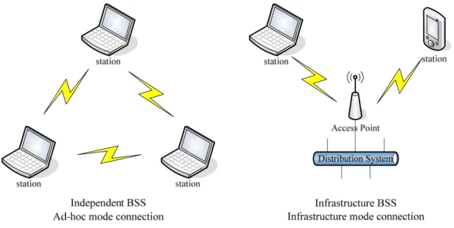
2.1 The IEEE 802.11 Wireless LAN Topologies
The 802.11 architecture is comprised of several components and services. The station
(STA) is the most basic component of the wireless network. A station could be a laptop PC,
handheld device, or an Access Point. Typically the 802.11 functions are implemented in the
hardware and software of a network interface card and all stations support the 802.11 station
service of authentication, de-authentication, privacy, and data delivery. The basic service set
(BSS) is the basic building block of WLAN and there are two types of network topologies, as
shown in Figure 2-1, independent BSS, and infrastructure BSS.
Independent basic service set is a set of stations, which have recognized each other and
are connected directly via the wireless media in a peer-to-peer fashion, and also is referred to
as an ad-hoc network. Some stations may not be able to communicate with every other station
due to the range limitations.
In the infrastructure basic service set, stations must be connected with a central serving
node, access point, to communicate with others and only through the AP they can
communicate with each other no matter how close they are.
Besides, as shown in Figure 2-2, multiple BSS can be combined to form an Extended
Service Set (ESS) to provide a larger radio coverage area, which contributes to roaming
convenience. In ESS, APs act as bridges and there is a server maintaining the IP information
and Internet access control of a station.
Figure 2-2: The Extended Service Set (ESS)
In each BSS, the BSSID (BSS Identity) is the MAC address of wireless interface of an
AP. The SSID (Service Set Identity) is a string identifier and can be viewed as the wireless
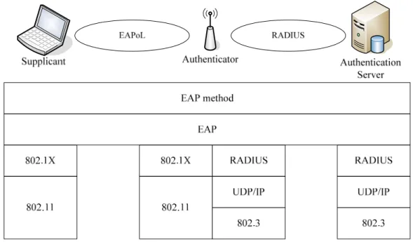
2.2 The IEEE 802.1X Authentication
The IEEE 802.1X [4] provides a port-based network access control mechanism for user
authentication, unlike the IEEE 802.11 authentication services, open system authentication
and shared key authentication, focus on device authentication. Almost all vendors implement
802.1X for APs addressing the security vulnerabilities of WEP (Wired Equivalent Privacy)
and 802.1X also plays a major role in the IEEE 802.11i which specifies security mechanism
for WiFi.
802.1X architecture has defined three components, as shown in Figure 2-3. The
supplicant is the user machine requesting for network resource access. Upon detection of the
new supplicant, the port of the authenticator will be enabled and set to the “unauthorized”
state. In this state, only 802.1X traffic will be allowed; other traffic, such as DHCP and HTTP,
will be blocked at the data link layer. It maintains no user information and just translates
authentication messages between supplicant and authentication server. There needs an
authentication server, for instance a RADIUS server, implementing various authentication
mechanisms.
802.1X is a framework based on Extensible Authentication Protocol (EAP) [5]. EAP
provides many authentication methods above it. The following are some EAP authentication
methods.
EAP-MD5: MD5-Challenge is analogical to the CHAP protocol. It requires that the
challenge should be successfully encoded with a shared secret. However, the MD5 hash
function is vulnerable of dictionary attacks, and doesn’t support mutual authentication.
EAP-TLS: Transport Layer Security (TLS) can be used to establish a trusted
communication tunnel over an unknown network subject to eavesdropping. It provides mutual
authentication through certificate exchange. However, it needs to have a well-built Public Key
Infrastructure (PKI) to generate and distribute certificate.
EAP-TTLS and EAP-PEAP: Both of them work similarly. First, they establish a TLS
tunnel similar to EAP-TLS. Then, the TLS tunnel is used to encrypt an older authentication
protocol that authenticates users to the network. Certificates are required only for outer
authentication. The difference between TTLS and PEAP is how they handle the inner
authentication. TTLS uses the tunnel to exchange AVPs (attribute-value pairs) while PEAP
uses the tunnel to start a second EAP authentication method.
EAP-MSCHAPv2: Microsoft CHAP version 2 (MSCHAPv2) can be used as inner
authentication method of PEAP. It was designed to address the shortcomings of MSCHAP and
provided mutual authentication.
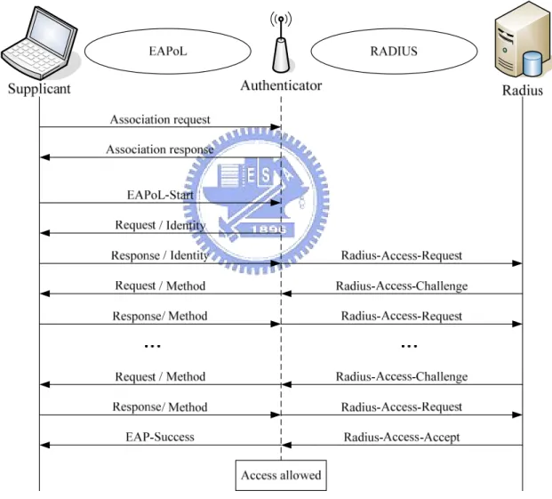
2.3 Typical 802.1X Authentication Message Exchange
There is an example of typical 802.1X authentication message change on 802.11 WLAN,
as shown in Figure 2-4. Once station scans and then associates with an AP, the supplicant will
EAP-Request / Identity message and the supplicant replies with the EAP-Response / Identity
message. Then the response will be translated by the AP to the RADIUS server as a
Radius-Access-Request packet. According to the type of EAP method required, the RADIUS
server encapsulates the EAP request for that method in a Radius-Access-Challenge packet to
the AP. When it reaches the AP, the EAP request is extracted and passed to the supplicant.
Depending on various EAP methods, there are different numbers of authentication message
exchange.
Figure 2-4: The typical 802.1X authentication message exchange
If the RADIUS server grants access by the Radius-Access-Accept packet, then the AP
issues the EAP-Success message and authorizes the port. After receiving the EAP-Success
won’t be blocked by the AP at data link layer any more. Then, gain the IP and enjoy Internet.
Otherwise, the RADIUS server sends the Radius-Access-Reject packet, and then the AP
issues the EAP-Failure message and keeps the port unauthorized. When the supplicant has
finished accessing the network resources, it can send the EAP-Logoff message to put the port
back into the unauthorized state.
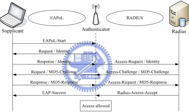
Figure 2-5 shows the typical 802.1X authentication using EAP-MD5 message exchange,
which is the basic authentication method.
Figure 2-5: The typical 802.1X authentication using EAP-MD5 message exchange
2.4 RADIUS
Remote Authentication Dial In User Service (RADIUS) [6] is an AAA (Authentication,
Authorization and Accounting) protocol for network access or IP mobility. You enter a
link-layer protocol, for instance AP through 802.11, then to a RADIUS server over the
RADIUS protocol. The RADIUS server checks that the information is correct using
authentication schemes like EAP.
RADIUS is also commonly used for accounting purposes [7]. The NAS can use
RADIUS accounting packets to notify the RADIUS server of events such as the user’s session
starting time, ending time, volume of data transferred and reason for session ending. The
primary purpose of the data is so that the user can be billed accordingly. RADIUS uses UDP
instead of TCP as transport protocol with port 1812 for Authentication and 1813 for
Accounting.
Next, we describe some attributes in RADIUS we used in 802.1X authentication [8] and
accounting service in our system.
In IEEE 802.1X, the supplicant typically provides its identity via an EAP-Response /
Identity message. Where available, the supplicant identity is included in the User-Name
attribute in the RADIUS Access-Request messages. Called-Station-Id attribute is used to
store the bridge or Access Point MAC address. But in IEEE 802.11, where the SSID is known,
it SHOULD be appended to the AP MAC address. Calling-Station-Id attribute is the
supplicant MAC address.
In RADIUS accounting message, Acct-Session-Time attribute indicates how many
seconds the user has received service. Acct-Terminate-Cause attribute shows how the
session was terminated. Besides, the total packets and volume of data transferred during the
session is recorded in Acct-Input-Octets, Acct-Output-Octets, Acct-Input-Packets and
2.5 Introduction of Linux Netfilter/iptables
Netfilter [9] is a framework inside the Linux kernel for intercepting and manipulating
network packets. Software inside the framework enables packet filtering, network address
translation (NAT) and other packet mangling. Netfilter is a set of hooks inside the Linux
kernel that allows kernel modules to register callback functions with the network stack. A
registered callback function is then called back for every packet that traverses the respective
hook within the network stack.
iptables is the name of the user space tool by which administrators create rules for the
packet filtering and NAT modules. iptables is a standard part of Linux 2.6.x kernel series. We
can use netfilter/iptables to build internet firewalls based on stateless and stateful packet
filtering and apply NAT and masquerading for sharing internet access.
There are three tables in Linux iptables, filter, nat and mangle. The filter table is
designed to filter packets; the nat table can perform source address masquerading and
destination redirection; the mangle table is used for mangling packets, like modifying the TTL
and TOS.
In our system, we focus on filter and nat tables. Each of them has three chains; filter
table holds INPUT, OUTPUT, FORWARD chains and nat table holds PREROUTING,
POSTROUTING, OUTPUT chains.
The packet flow of our system in iptables is shown in Figure 2-6. When packets arrive,
the packets of unauthorized users will be redirected to the proxy server in local host by the nat
table PREROUTING chain. The filter table FORWARD chain controls all forwarding traffic
in network layer. Finally, the nat table POSTROUTING chain masquerades the address for IP
Chapter 3 The Design of Our System
First, we describe the system architecture and system components. Our system focuses
on a generalized and scalable platform for sharing Internet access through WLANs. In order
to achieve generalization, we use 802.1X, which is the most popular authentication protocol
built in APs, to authenticate users in an infrastructure BSS, as described in Section 3.2. And
we define the message exchanges of TCP packets as our authentication method in an
independent BSS, as described in Section 3.3. To realize scalability, we consider the
integration of both ESS and ad-hoc networks, as described in Section 3.4 and 3.5.
3.1 The Overview of Our System
The whole system consists of two types of BSSs and an AAA server. Figure 3-1
illustrates the system architecture. In an infrastructure BSS, users can access the Internet
through AP after being authenticated by the server. A node connecting to the Internet and
equipping two NICs can be a portal. A portal is an access point of Internet in an independent
BSS. AAA server, AP, portal and node are four components of our platform.
There are two goals that we want to achieve. First, any AP can join the sharing
community through 802.1X. If we have no AP, we can also share our broadband Internet
access through an ad-hoc WLAN. Second, the coverage area is extended as far as we can. For
the users, we want to provide an easy-configured environment for both the consumers and
providers of Internet access. In addition an Internet service provider can also join the sharing
group as an ESS.
There are four basic components in our platform, including an AAA server,
authenticators, nodes and a portal.
An AAA server is responsible for authenticating and authorizing the users for Internet
access, and also provides the accounting service. The server is supposed to be well known
such that every AP and portal knows where to connect. The server is comprised of RADIUS,
ad-hoc server and user account database. An account is a universal account for both
infrastructure and independent BSSs, but the authentication methods are different.
In 802.1X, authenticators usually are access points. In our system, we require APs to
support 802.1X authentication and recommend APs to equip RADIUS accounting service.
A node is a device with a WLAN interface. It can access Internet through an AP or a
portal. But in an ad-hoc network, it needs ad-hoc routing capabilities to construct a path from
the node to the portal.
When a node connects ad-hoc nodes to the Internet, it will be referred to as a portal. A
portal acts as the access point in an ad-hoc network and makes ad-hoc nodes connect to the
Internet possible. A portal not only controls the access of the Internet but also provides IP
sharing service. However, not any node can be a portal. There is a constraint for a portal. A
portal needs two network interfaces, one for Internet access and the other for point-to-point
To join the sharing group, a user has to register an account on the web and keep the
password. In addition, each user is given initial credits. A user can earn credits by providing
Internet access to other users, or spend credits to use other users’ APs.
3.2 Infrastructure BSS
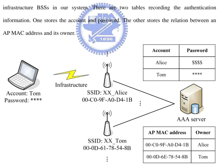
After registering an account, a user is asked to register his or her shared AP on the web.
For the purpose of accounting, we care about not only the MAC address of a shared AP but
also the owner. The web page will ask for the AP MAC address and the owner’s account, and
return a server-assigned SSID and RADIUS server. The SSID should be in “XX_ID” form;
XX is an indication of a shared AP and ID denotes the owner. Figure 3-2 depicts sharing
infrastructure BSSs in our system. There are two tables recording the authentication
information. One stores the account and password. The other stores the relation between an
AP MAC address and its owner.
If an AP follows RFC3580 802.1X RADIUS usage guideline, SSID should be appended
to the AP MAC address of the Called-Station-Id attribute in a RADIUS packet. After AP
registration on the web, the owner should set the SSID of the AP to the server-assigned one.
Then, the owner’s ID will be carried in RADIUS packets and the RADIUS server can know
who provides the resource and thus receives the credits. In this case, the relation between an
AP and its owner needs no verifications in advance.
However, not all APs follow RFC3580. For the APs that doesn’t, there is no information
about the owner brought in their RADIUS packets. In order to verify the relation between an
AP and its owner, the web page of AP registration assigns a RADIUS server randomly chosen
from several ones. The owner should configure the RADIUS server where it is in his AP and
use his own account to do 802.1X authentication once within a short period of time to confirm
the relation between APs and users. This is based on the idea that someone who can modify
the configuration of the AP is the owner.
The support of 802.1X authentication on APs is required but the RADIUS accounting
function is optional. Depending on the ability of the authenticators, we classify them into two
scenarios. If an AP supports accounting, it is the ideal scenario. We can apply it to support
charging by time or volume of data transferred. Otherwise, we just can only support charging
by the number of times of login, because the AAA server never knows when the supplicant
leaves if the AP doesn’t inform.
After finishing the setup of an AP, we use EAP-PEAP as our 802.1X authentication
method, which is the most popular one built in Microsoft OS. EAP-PEAP requires only a
server-side PKI certificate to create a secure TLS tunnel to protect user authentication. Figure
3-3 shows the message flow of 802.1X authentication using EAP-PEAP. When the encrypted
tunnel is established, we use EAP-MSCHAPv2 as the inner authentication. If the account and
the supplicant usually delivers a DHCP request to get an IP address.
Figure 3-3: Message flow of 802.1X authentication using EAP-PEAP
3.3 Independent BSS
If a user has no AP, he or she can share the broadband Internet access through an ad-hoc
WLAN. We want some device more widespread, such as a notebook PC, to replace an AP and
achieve what an AP can do through the device which is named portal in our system. Sharing
can be realized relying on the forward of a portal, which connects other nodes through a
point-to-point connection to the Internet. But there is a constraint being a portal. A portal
should be equipped with two network interfaces, one for ad-hoc connection with other nodes
and the other for Internet access. The first one must be wireless, but the second one can be
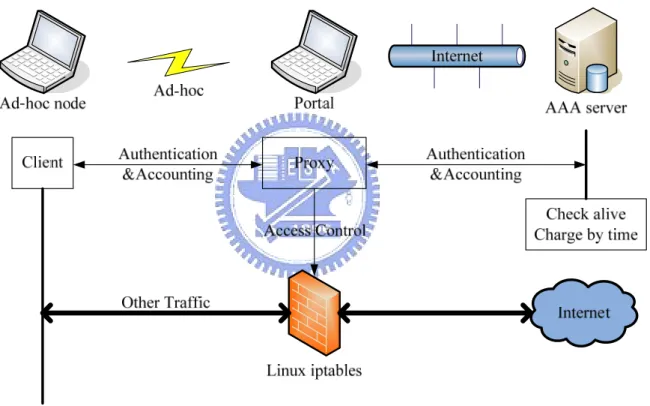
Figure 3-4 shows the system architecture of a sharing independent BSS. A portal is an
access point of Internet for an ad-hoc network and makes ad-hoc nodes connect the Internet
possible. In a portal, there is a program controlling the access of the Internet. The program
commands Linux iptables to carry out the Internet access control of the ad-hoc nodes. The
packets of unauthorized users will be redirected to the program and the program, like a proxy,
relays only the traffic of authentication and accounting to an AAA server. After authorization,
other traffic can be forwarded in network layer and be masqueraded as the traffic from the
portal. Then, authorized ad-hoc nodes can access Internet through a portal.
Figure 3-4: System architecture of a sharing independent BSS
In an independent BSS, 802.1X is not an appropriate mechanism for network admission
control because access control in 802.1X is based on the MAC address at data link layer.
However, it is possible that ad-hoc nodes don’t connect a portal directly, relayed by other
nodes instead. In this situation, a portal can’t distinguish the unauthorized traffic from the
traffic of authorized node just by the MAC address. A portal only knows the MAC address of
We create an authentication and accounting mechanism based on the IP address. After
exchanging the DHCP messages, an ad-hoc node gets its IP and use the client program to
establish a TCP connection with the proxy program in a portal. The program will relay only
the traffic of authentication and connect an AAA server also through TCP. Because TCP is
connection-oriented, we apply the feature to check if ad-hoc nodes are still alive. From
authorization until termination of the client program, it can be charged by time.
The ad-hoc authentication message flow is similar to the EAP-MD5. Figure 3-5 shows
the message flow of ad-hoc authentication in our system. The node triggers the authentication
by sending a TCP message with his identity. After receiving the message, the portal appends
his owner’s identity and start to relay for the node and the AAA server. The server will
challenge the node a concatenation of a random clear text and the portal owner’s identity.
Then, the client should response the result of MD5 hash function taking password to encrypt
the concatenation. So password will not be sent in the message. If MD5 check is correct,
access is granted and the node starts pay credits to the portal owner.
3.4 Integrate with ESS
To provide a larger radio coverage area, an ISP can combine multiple BSSs into an ESS,
which also enables a node to roam among the BSSs. Generally speaking, an ESS consists of a
server and some APs which are deployed by the same unit, like a school or a community. For
the reduction of deployment cost, these APs are usually simplified as wireless bridges, which
remove the IP addressing and access control function form AP to a local server. The server
maintains an IP pool for the DHCP requests from the supplicants and controls the traffic
between LAN and WAN.
In our platform, we do not focus on the roaming and handoff issues. Each general AP
maintains his own DHCP and NAT functions for client IP addressing. There is no relation
between two BSS even though there is cover in their physical radio coverage area. But it is
different in an ESS that there is a local server maintaining the IP and access control
information of all clients. An ESS appears as a single BSS to the logical link control layer at
any station associated with one of those BSS. In such situation, roaming in an ESS is possible
and how to speed up the handoff latency is a well-known problem.
If we treat an ESS like an AP with a larger radio coverage area, an ESS can join our
sharing group as a BSS. Figure 3-6 shows the integration of an ESS and our platform. Only
one requirement is that the local server supports 802.1X authentication. The local server plays
a major role in an ESS, such as IP addressing, access control, authentication message
translation and roaming. So we take the MAC address of the local server as a representation
of the ESS. And the SSID should be XX_ID which the ID may be the name of an ISP or a
school. The same thing we should do in BSS or ESS is the assignment of the AAA server
Figure 3-6: The integration of an ESS and our platform
3.5 Integrate with ad-hoc networks
There are two main challenges in the scalability of ad-hoc networks. The first one is IP
addressing. In our system, there is a DHCP server in the portal for the address allocation of
ad-hoc nodes. However, DHCP requests are not relayed by other ad-hoc nodes unless there is
a DHCP proxy in every node. It is not the best solution and there are already many researches
about address assignment in an ad-hoc network [10]. The second challenge is an ad-hoc
routing algorithm, such as AODV (Ad-hoc On-demand Distance Vector routing algorithm) or
OLSR (Optimized Link State Routing protocol) [11]. They both control the routing table to
ad-hoc nodes. For node A, the routing table means that the traffic to node P should be
forwarded by node C and hop count from A to P is 2.
A C 2 B D 2 Internet P C 2 A P D 2 P P 1 P P 1 Routing Table
Target Next Hop Hop #
B D
P
C AAA server
Figure 3-7: An example of the routing tables in ad-hoc nodes
We don’t care how the algorithms work, but once a path from the node to the portal is
established, we still can apply our mechanism to authenticate users in our sharing group.
Because our ad-hoc authentication and accounting methods are based on the IP address, we
Chapter 4 System Implementation
Figure 4-1 depicts the system we have implemented. We used one wireless AP, one
desktop and two laptop PCs to exhibit our sharing platform. The AP acts an authenticator. The
desktop PC is used as the AAA server. One laptop PC with two wireless NICs serves as the
portal; the other is a user machine.
Internet
ASUS WL500g AAA Server Portal Infrastructure Node Ad-hoc Node Ad-hoc A d-hoc Independent BSS Infrastructure BSS
Figure 4-1: The system we have implemented
We hope more users can join our sharing group, so we leave no constraint on APs and
WLAN interfaces. We choose ASUS WL500g as our demo authenticator and the Intel® PRO
/ Wireless 2200BG as our client’s wireless interface. In Linux, we also can use Xsupplicant
[12] as 802.1X client-side program.
4.1 The Implementation of the AAA server
We use the Linux OS of Fedora Core 5 as our development environment for AAA server.
There are three basic components describing as follow, including a RADIUS server, ad-hoc
A RADIUS server is responsible for authenticating, authorizing and accounting the user
Internet access ability in infrastructure BSS. We have implemented our mechanism by using
the open source code project, FreeRADIUS [13]. It also can be treated as an 802.1X server
and provide many authentication methods above EAP. We take EAP-PEAP as our 802.1X
authentication method to establish an encrypted tunnel and EAP-MSCHAPv2 as the inner
authentication. FreeRADIUS supports not only account files but also many types of back-end
databases.
An ad-hoc server is designed to authenticate, authorize and account users in an
independent BSS. It is a self-created AAA server which can query account database. Our
ad-hoc authentication method simulates EAP-MD5 and we apply TCP connection to detect
node alive for accounting. Figure 4-2 shows the flow chart of each connection in ad-hoc
server.
1. Receiving request contains user’s identity and portal owner’s identity.
2. Take user identity to query account database corresponding password. Use
password to MD5 hash the concatenation of the challenge and the portal identity.
Check the result and the response is identical.
3. Charged by time from authorization until termination of the TCP connection.
MySQL [14] is a multithreaded SQL database management system, and we apply
MySQL to maintain our accounting information. The RADIUS and ad-hoc server connect the
same database, so an account is universal for two BSS. There are four entity sets containing
several attributes in our database, as shown in figure 4-3.
1. Entity set “acctcheck” stores user name and password.
2. For every authentication, record the user name, mode (infrastructure or ad-hoc),
portal owner and timestamp in Entity set “sharepostauth”.
3. Entity set “adhocacct” is used for ad-hoc mode accounting consisting of user name,
login time, logout time, session interval, portal owner and termination cause.
4. Entity set “radacct” works depending on that AP supports RADIUS accounting.
Besides time, volume of incoming and outgoing data transferred can be logged.
sharepostauth index UserName Mode Portal Date acctcheck index UserName Password radacct index UserName AcctStartTime AcctStopTime AcctSessionTime CalledStationId CallingStationId AcctInputOctets AcctOutputOctets AcctTerminateCause adhocacct index UserName AcctStartTime AcctStopTime AcctSessionTime Portal AcctTerminateCause
Figure 4-3: The entity sets with attributes in our database
4.2 The Implementation of the Portal
A portal is a node, which connects other ad-hoc nodes to the Internet. Because we apply
netfilter to do access control, the environment is forced to Linux. We take some laptop PC
A proxy is a program in the portal dealing with the exchange of accounting messages and
access control. Figure 4-4 shows the flow chart of each connection in the proxy. When
someone wants access the Internet, we check whether message format is correct first. Then,
the proxy connects the ad-hoc server and relays the traffic of accounting. If the server grants
the access, the proxy updates iptables to accomplish it. Until client terminates the connection,
the proxy will terminate the connection with server and update iptables again to block the
access.
4.3 Comparisons and Evaluation
Our approaches are the power of users and no modification on the APs. The following
table lists the comparisons between WIFLY, FON and our platform. WIFLY and FON have
strict constrains on APs. WIFLY needs the highest deployment cost. WIFLY can provide the
better wireless QoS because the whole deployment of the hotspots. FON provide only home
users (H) bandwidth control function. For visitors (V), FON is like our platform. There is no
guarantee for wireless QoS. Except home users in FON, the others care no security in WLAN.
WIFLY FON Our platform
Constrains Specific APs FON Social Routers APs support 802.1X
Deployment Cost High Low Low
(H) Bandwidth Control Wireless QoS Better
(V) No No guarantee (H) WPA Encryption Wireless Security No (V)No No
Chapter 5 Conclusions
In this thesis, we propose a generalized and scalable platform for sharing wireless
Internet access. We believe that FON taking the power of users is a better approach than
WIFLY. However, both of them need specific type of APs to work. We present a general
approach to enable more users to join a sharing group. Our requirements are 802.1X in an
infrastructure BSS and TCP message exchanges in an independent BSS to support user
authentication.
The most important part in the sharing platform is the AAA server and the users. The
more users join the sharing group, the larger the coverage of WiFi is. A larger-scale WiFi
network would attract more and more users to join us. To make the idea come true, we should
level down the entry barrier. But no modification of the APs also brings us some problems.
For example, we can not guarantee the wireless QoS and security. Although FON announced
that they have enhanced these features, the effect is partial. FON uses bandwidth control and
WPA key encryption to protect only home users. For visitors, the problems still exist. In our
system, there are still many security holes in the accounting mechanism. Repairing these holes
is difficult without modification of the APs, and the merit is limited. This is a tradeoff
between popularity and security, and we choose the first one.
In addition, we can integrate ESSs and ad-hoc networks into our sharing platform. Our
original sharing platform does not support roaming, but roaming in an ESS is possible. No
matter what kind of handoff algorithm is applied, an ESS supporting 802.1X can join us as a
BSS. The two main challenges in ad-hoc networks are IP addressing and ad-hoc routing
capabilities. Once a routing path is addressed and established, we can apply our method to
authenticate users connected through ad-hoc networks to the sharing group.
can improve in the future. For instance, the security holes, roaming or ad-hoc addressing and
Reference
[1] WIFLY, an outdoor wireless Internet access service, URL: http://www.wifly.com.tw
[2] FON, the largest WiFi community in the world, URL: http://www.fon.com/en
[3] Mattbew S. Gast, “802.11 Wireless Networks: The Definitive Guide”, second edition,
book, April 2005
[4] LAN MAN Standards Committee of the IEEE Computer Society, “802.1X: Port-Based
Network Access Control,” IEEE Std 802.1X-2004
[5] B. Aboba, L. Blunk, J. Vollbrecht, and J. Carlson, “Extensible Authentication Protocol
(EAP),” IETF RFC 3748, June 2004
[6] C. Rigney, S. Willens, A. Rubens, and W. Simpson, “Remote Authentication Dial In User
Service (RADIUS),” IETF RFC 2865, June 2000
[7] C. Rigney, “RADIUS Accounting,” IETF RFC2866, June 2000
[8] P. Congdon, B. Aboba, A. Smith, G. Zorn and J. Roese, “IEEE 802.1X Remote
Authentication Dial In User Service (RADIUS) Usage Guidelines,” IETF RFC 3580,
September 2003
[9] Netfilter, the software of the packet filtering framework inside the Linux, URL:
http://www.netfilter.org/
[10] Mansi Ramakrishnan Thoppian and Ravi Prakash, “A Distributed Protocol for Dynamic
Address Assignment in Mobile Ad Hoc Networks,” January 2006
[11] Vikas Kawadia, Yongguang Zhang and Binita Gupta, “System Services for Ad-Hoc
Routing: Architecture, Implementation and Experiences,” 2003
[12] Open1x, Open Source Implementation of 802.1X, URL: http://open1x.sourceforge.net/
[13] FreeRADIUS, the premiere open source RADIUS server, URL:
http://www.freeradius.org/