Simple analytical method of cavity design
for astigmatism-compensated Kerr-lens
mode-locked ring lasers and its applications
Kuei-Huei Lin, Yinchieh Lai, and Wen-Feng Hsieh
Institute of Electro-Optical Engineering, National Chiao Tung University, Hsinchu, Taiwan 30050, China
Received January 19, 1994; revised manuscript received September 27, 1994
An analytical method based on a renormalized q parameter for Gaussian-beam propagation and properly matched self-consistent complex q parameters is proposed to aid in the design of arbitrary-astigmatism-compensated Kerr-lens mode-locked ring cavity lasers. The q parameters throughout the ring cavity can be calculated by solution of an algebraically quadratic equation for an arbitrarily thick Kerr medium when the intracavity laser power is less than the self-trapping power. The Kerr-lens mode-locking strength at the curved mirror was calculated over the stable range. The results indicate that the astigmatism is best compensated so that the stable range of x and y directions have optimal overlapping. Although to maximize the hard-aperturing effect the curved mirror separation must be at the far edge of the stable range, pump and cavity field matching inside the Kerr medium is also necessary. In addition, the insertion of a vertical slit is more effective than insertion of a horizontal slit. A spiking phenomenon is found in the intracavity z scan curve, which can be observed only with thick Kerr materials and a high laser power.
1.
INTRODUCTION
Since the first observation of the self-mode-locking phe-nomenon in a Ti:sapphire laser1 much attention has
been given to both experimental and theoretical inves-tigations of self-mode-locked lasers.2–12 The
self-mode-locking mechanism is now attributed to the optical Kerr effect inside the Ti:sapphire crystal; thus the mecha-nism is termed Kerr-lens mode locking (KLM). Owing to the instantaneous response of the Kerr nonlinear-ity, a fast saturable absorber effect can be obtained in these laser cavities if proper soft or hard apertur-ing is added to yield amplitude modulation. Numerous standing-wave and ring-laser resonator designs as well as experimental techniques have been reported.2–4
Re-cently pulses as short as 11 fs were generated directly from a standing-wave-cavity KLM Ti:sapphire laser after the intracavity dispersion compensation was optimized.2
With a position-modulated mirror used in an external cavity, the ring-cavity Ti:sapphire laser can initiate self-starting in milliseconds,4 and extremely short pulse
widths should also be obtainable, because the disper-sion of the Ti:sapphire crystal is a factor of 2 less than that of standing-wave-cavity configurations. Various nu-merical and analytical methods have been developed to study standing-wave and ring-cavity KLM lasers.5–9 By
the numerical Hankel transform method, Pearson et al.5
adjusted crystal and hard-aperture positions to maxi-mize the slope of aperture loss versus power.5 Among
the analytical methods, most research is based on the assumption of low intracavity laser power and thin-Kerr-medium approximations. Using both approximations, Georgiev et al.6 derived a matrix representation for the
Kerr medium; by this a time-independent Gaussian-beam analysis of a standing-wave cavity KLM laser resonator was performed. With the cavity beam-waist position and
the confocal parameter as variables, the KLM cavity can be described by one set of two-variable quartic equations, and the changes in round-trip gain versus intracavity power were discussed for the thin-Kerr-medium case.7
By cascading the numerical complex beam-parameter manipulation in a thin Kerr medium and the linear
ABCD-matrix manipulation in free space, Heatley et al.8
described the Kerr-lens effects and unidirectional opera-tion in a ring cavity with an aperture.8 In another study
the concept of self-shortening was introduced and the non-linear ABCD matrix was used to describe the propagation of Gaussian beams in materials with Kerr nonlinearity.9
Although the applicable power range and medium thick-ness of this formalism are less restrictive than those of former methods,5–8for analysis of the KLM cavity the
con-tinuous wave (CW) cavity parameters must be calculated before the nonlinear ABCD matrix is obtained, which in-creases the design complexity. By renormalizing the q parameter in a Kerr medium, Haus et al.10 showed that
a problem involving self-focusing can be analyzed like that of free-space propagation, and they developed an analytic theory of a laser cavity with a Kerr medium of any thickness located against an end mirror. In previ-ous research11we proposed a simple analytical approach,
based on the concept of the renormalized q parameter10
and the self-consistency of q parameters, for the design of standing-wave cavity KLM lasers. With this approach the order of the equations is reduced by a factor of 2. We found that the cavity-beam spot size can be described by a single-variable quartic equation, which can be further reduced to a quadratic equation in the symmetrical case. Various optical properties, such as the stability range, power-dependent beam spot sizes, and KLM strength throughout the cavity can be calculated algebraically.
In this paper we extended our formalism to arbitrary ring-cavity lasers. By properly choosing the self-similar
point in the laser cavity, we found that the Gaussian-beam q parameters can be again calculated from a quadratic equation, and the design work is drastically simplified. With this approach the beam spot sizes throughout the ring cavity can be calculated for an ar-bitrary Kerr-medium thickness and an intracavity laser power less than the self-trapping power. We found that the astigmatism is best compensated so that the stable range of x and y directions have an optimal overlap. Al-though to maximize the hard-aperturing effect the curved mirror separation must be located at the far edge of the stable range, pump and cavity field matching inside the Kerr medium is also necessary. In addition, the in-sertion of vertical slit at the first mirror, M1, is more
effective than insertion of a horizontal slit. In the in-tracavity z-scan study we found a spiking phenomenon caused by the drastic alteration of Gaussian modes in the cavity that was due to the competition of the focus-ing power of the Kerr medium and the curved mirrors. This phenomenon can be observed only with thick ma-terials and a high intracavity laser power. One must be careful in analyzing the z-scan data under such cir-cumstances.
2.
THEORY
To develop an analytic theory of KLM lasers, we use the q representation of a Gaussian beam. The Gaussian field envelope is assumed to be of the following form:
U A0 exps2jwdexp √ 2j 2 2pn0 l r2 q ! . (1)
Here A0 is the amplitude, w is the longitudinal phase,
n0is the linear refractive index, and l is the wavelength.
The complex q parameter is related to the beam curvature
R and beam radius w by the following expression:
1 q 1 R 2 j l n0pw2 . (2)
By approximating the self-phase shift DF in the Kerr medium of length dz by a parabola,
DF 2p l n2A0 2exp √ 22r2 w2 ! dz . (3a) ø 2p l n2A0 2 √ 1 2 2r 2 w2 ! dz , (3b) where n2 is the nonlinear refractive index, Haus et al.
showed in Ref. 10 that the propagation equation of 1 /q satisfies 2 d dz √ 1 q ! 1 q2 1 K Im 2 √ 1 q ! , (4)
where the Kerr parameter K is defined as
K 8P p √ p l !2 n0n2. (5)
Here P is the cavity power. After renormalizing the q parameter as 1 q0 Re √ 1 q ! 1 j Im √ 1 q ! p 1 2 K , (6) Haus et al. found
2 d dz √ 1 q0 ! 1 q02. (7)
The above equation is identical with the free-space propa-gation equation of 1 /q. Therefore when the q parameter is renormalized, the problem involving self-focusing can be analyzed like that of free-space propagation.
To fit the solution with experimental data,12we can
in-troduce an adjustable correction for a into the expression for the Kerr parameter K. The definition of K is modi-fied to be K PyPcr, with Pcr al2ys8pn0n2d. Here a
is the correction factor and Pcris the critical power of
self-trapping. With the introduction of the correction factor, the above formulation should be accurate enough even for high beam powerssP ø Pcrd.
Consider a four-mirror figure-8 ring cavity as shown in Fig. 1. M1 and M2are curved mirrors with focal length
f, M3 and M4 are flat mirrors, and a Kerr medium with
length t is located between the curved-mirror pair. Let the 1 /q parameter at endface I be 1yqI 1yRI2 js1yyId
1yRI2 jflyspwI2dg and the ABCD matrix from endface I
by way of M1, M3, M4, and M2to endface II be
"
A B
C D
# ;
then the 1 /q parameter at endface II can be calculated by the ABCD law as
1 qIIM f yI2sARI1 Bd sCRI1 Dd 1 BDRI2g 2 jyIRI2 yI2sARI1 Bd21 B2RI2 . (8) Now, if we choose the positive propagation direction to be from endface II to endface I and use the renormalized
q parameter method to transform 1 /qIthrough the Kerr
medium to endface II, the 1 /q parameter at endface II is calculated to be 1 qIIL f yI2RI2 LyI22 LRI2s1 2 Kdg 2 jyIRI2 yI2RI22 2LyI2RI1 L2yI21 LRI2s1 2 Kd , (9)
Fig. 1. Four-mirror figure-8 ring cavity laser with a Kerr medium of length t placed between two curved mirrors. M1
and M2are curved mirrors with focal length f. M3and M4are
flat mirrors. The coordinate conventions are chosen such that the z axis is along the propagation direction of the laser beam.
where L tyn0is the effective length of the Kerr medium.
We can prove the reversibility of the q-parameter trans-formation in the Kerr medium to be true by transforming 1 /qIIL through the Kerr medium to endface I, and we
ob-tain 1yRI2 js1yyId (see Appendix A).
According to the self-similar condition for stable laser resonators, 1 /qIIM must be equal to 1 /qII L. Using this
condition and after some algebraic manipulations, we have fLs1 2 Kd 1 BDg fsARI1 Bd22sRI2 Ld2g 1fL2s1 2 Kd 2 B2g 3fsARI1 Bd sCRI1 Dd 2 RI1 Lg 0 , (10) yI2 RI2fL2s1 2 Kd 2 B2g sARI1 Bd22sRI2 Ld2 . (11) Equation (10) is a quadratic equation of RI. We first
solve this equation to get RI. Since yI is a function of RI[Eq. (11)], the value of yI is obtained after RI is
sub-stituted into Eq. (11). The beam radius wIis calculated
as wI slyIypd1/2. Therefore the KLM strength can be
calculated according to the definition6
F 21 w dw dP É P0 .
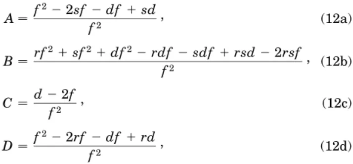
The ABCD matrix elements from endface I to endface II are A f 22 2sf 2 df 1 sd f2 , (12a) B rf 21 sf21 df22 rdf 2 sdf 1 rsd 2 2rsf f2 , (12b) C d 2 2f f2 , (12c) D f 22 2rf 2 df 1 rd f2 , (12d)
where r is the distance between M1 and endface I, s is
the distance between M2 and endface II, and d is the
distance from M1 by way of M3 and M4 to M2. With
these matrix elements substituted into Eqs. (10) and (11), the Gaussian-beam curvature RI and beam radius wI at
endface I can be calculated. With the ABCD transfor-mation and the renormalized q-parameter definition, the Gaussian-beam curvature and spot size (beam diameter) inside the Kerr medium and throughout the ring cavity are also known.
3.
ASTIGMATISM COMPENSATION
For most end-pumped standing-wave or ring-cavity solid-state lasers, the gain medium is often Brewster-angle cut and tilted to minimize surface-reflection loss. The two transverse x (normal to the plane of cavity) and y com-ponents of a Gaussian beam will thus propagate different effective distances through the gain medium, given by (as-suming the axis conventions shown in Fig. 1)
Lx L , (13a) Ly Lyn02. (13b)
Here L tyn0 and t is the length of the gain medium.
Since the cavity curved mirrors are also tilted by an angle u, they will focus parallel rays in the two transverse planes at different locations, leading to different effective focal lengths in the transverse planes. The two effective focal lengths are given by
fx fycos u , (14a) fy f cos u . (14b)
Because of these effects astigmatism is introduced and leads to elliptical Gaussian beams in the folded cavity,13
which will limit the performance of the laser system. To understand the astigmatic phenomena occurring in the KLM ring-cavity solid-state lasers, consider the figure-8 Ti:sapphire ring-laser cavity (as shown in Fig. 1) with f 5 cm, d 170 cm, and a Ti:sapphire rod st 2 cmd as the Kerr medium sn0 1.76, n2
3 3 10220 m2 W21, correction factor a 5.35, and
Pcr 2.6 MW, as in Ref. 12). Output coupler M4 is
located 120 cm from M1. Replacing L and f of Eqs. (10)
and (11) with the corresponding effective quantities of Eqs. (13) and (14), respectively, we plot in Fig. 2 the CW output spot sizes as functions of distance between the two curved mirrors (r 1 s 1 t) in the case with no astigma-tism compensation. We find that the stability ranges of the two transverse modes (2wx and 2wy) do not overlap;
therefore it is impossible to adjust the laser for lasing. We must tilt the curved mirrors to optimize the over-lap between transverse modes as well as maximize the stability range in which round mode-locked output laser beams can be obtained.
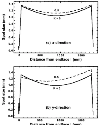
Figure 3(a) shows the astigmatism-compensated spot sizes 2wxand 2wyat the output coupler for CW operation
with K 0; the compensation angle is u 15.8±. We
see that wx is approximately equal to wy between a
113-and a 118-mm curved-mirror separation, 113-and the output Gaussian beam will be round; outside this curved-mirror separation range, wx is not equal to wy, and the output
Gaussian beam will be oval shaped. We also note that the wx stability range is broader than the wy stability
Fig. 2. Astigmatic CW spot sizes 2wxand 2wyof the two trans-verse modes at the output coupler as functions of the distance be-tween the curved mirrors. The cavity parameters are f 5 cm, t 2 cm, and d 170 cm.
Fig. 3. Astigmatism-compensated spot sizes 2wx and 2wy of the two transverse modes at the output coupler as functions of the distance between the curved mirrors with astigma-tism-compensation angle u 15.8±. (a) CW operation; (b) KLM
operation.
range. Figure 3(b) shows that the spot sizes 2wxand 2wy
are almost equal under KLM operationsK 0.5d for u 15.8±within the same range of curved-mirror separations.
Using K 0.5 in our calculation is reasonable because Ref. 4 reported a 60-fs Ti:sapphire laser with 2-W aver-age output power from 21% output coupler, from which we calculated the intracavity peak power as 1.7 MW for a typical 100-MHz repetition rate, corresponding to K 0.65; Ref. 14 reported 20-fs pulses with peak powers as high as 500 KW from a regeneratively initiated, self-mode-locked Ti:sapphire laser with a 10% output coupler. The intracavity peak power is 5 MW, which is larger than Pcr.
4.
CAVITY DESIGN AND PUMPING
ARRANGEMENT
We first solve Eqs. (10) and (11) to obtain the q param-eter at endface I of the Ti:sapphire rod; then the curvature
R and beam radius w throughout the
astigmatism-compensated cavity can be calculated by the ABCD transformation and renormalized q-parameter definition. With the Kerr medium located at a 1-mm displacement toward M1, we plot in Fig. 4 the KLM strengths at M1
as a function of curved-mirror separation. For effective hard aperturing, the curved-mirror separation must be adjusted to the far edge of the stable range (see Fig. 4), larger than 116 mm (for the x direction) for insertion of a horizontal slit at M1and 114 mm (for the y direction) for
a vertical slit. The fact that the positive hard-aperturing KLM strength for the y direction is always larger than
that for the x direction indicates that insertion of a ver-tical slit is more efficient than insertion of a horizontal one if a slit is used instead of an aperture.15 To
illus-trate the different behaviors of the two transverse modes in KLM, we plot in Figs. 5(a) and 5(b) the beam spot size variations in the x and the y directions, respectively, throughout the ring cavity as functions of the distance z from endface I under cavity powers K 0 and K 0.5 with a curved-mirror separation of 115 mm. We found that at this curved-mirror separation the spot sizes of the high-intensitysK 0.5d field are always greater than that of CW operation in the x direction; therefore it is im-possible for a horizontal slit to be used for hard-aperture
Fig. 4. KLM strength at M1versus the curved-mirror
separa-tion for the x and the y direcsepara-tions.
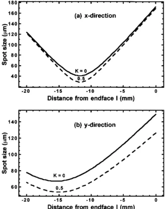
Fig. 5. Calculated spot size throughout the laser cavity for (a) the x direction and (b) the y direction as functions of the distance from endface I under different cavity powers K 0 and K 0.5. The distance between the curved mirrors is 115 mm.
Fig. 6. Calculated spot sizes inside the Ti:sapphire crystal for (a) the x direction and (b) the y direction as functions of the distance from endface I under different cavity powers K 0 and K 0.5. The curved-mirror separation is 115 mm. The x beam waist is located 1.8 and 1.6 mm from the center of Kerr medium toward M2for K 0 and K 0.5 respectively, whereas
the y beam waist is located 5.4 and 5.0 mm from the center of Kerr medium for K 0 and K 0.5.
KLM. However, the spot sizes of the high-intensity field are smaller than that of CW operation in the y direction for 0 , z , 275 mm; thus it is still possible for a vertical slit to be used for hard-aperture KLM.
In addition to proper aperturing for self-mode-locking, pump and cavity field matching inside the Kerr medium is also necessary for optimal energy extraction. Figures 6(a) and 6(b) show the spot sizes within the Kerr medium in the x and the y directions, respectively, for a curved-mirror separation of 115 mm. The displacement of x and y beam waists for both K 0 and K 0.5 is a result of astigmatism induced by the tilted curved mirrors, the Brewster-cut endfaces of the Kerr medium, and the 1 mm translation of the Kerr medium toward M1. The results show that the x beam waist is located
1.8 mm from center of the Kerr medium toward M2
and moves 0.2 mm to the right while the cavity power increases to K 0.5 [see Fig. 6(a)], whereas the y beam waist has a displacement with respect to the center of the Kerr medium toward M2of 5.4 mm for K 0 and of
5.0 mm for K 0.5. For the most efficient pump-cavity field matching, one has to adjust the pumping lens by an angle up with respect to normal incidence in the y – z plane and by a distance dp toward the incident
surface of M2 to compensate for the astigmatism until
a precise overlapping of pump and KLM cavity fields is achieved. When the pump beam passes through the pump lens (focal length 12.7 cm) and M2 (tilted by 15.8±,
see Section 3; thickness 9.5 mm), which is considered
a negative lens with focal length of 2200 mm for the pump beam, and the pump beam then goes into the Brewster-cut Kerr medium, it is trivial to write the cor-responding ABCD matrix for the given location of the x and y beam waists (i.e., 8.4 and 5 mm for K 0.5 from Brewster-cut face II) and to solve for up and dp. Using
an Ar1 laser as the pump source (with a typical 1-mm
beam radius and a 514.5-nm wavelength), one obtains up 9.2±and dp 79.7 mm to match completely beam
waists of the pump and KLM cavity fields.
5.
INTRACAVITY z SCAN
The external cavity z-scan technique has proved to be a simple and sensitive method for measuring the non-linear refractive index n2 of Kerr materials.16 The
z-scan result shows a quasi-antisymmetrical curve in the
transmittance-position diagram, with peak and valley transmittances separated by ,1.7 diffraction lengths of the Gaussian beam. Since the Kerr material in this figure-8 cavity is placed between focusing mirrors, a
z-scan-like action may also be present.8 The sensitivity
of intracavity z-scan measurement of nonlinear refractive index and absorption will be much better than that of the external z-scan method, because the intracavity laser power is 1 /T times (T is the transmittance of the out-put coupler) higher than the external cavity laser power. To understand the effect of Kerr medium displacement on the spot size variations, we consider the Ti:sapphire laser with fixed mirror positions; the distance between the curved mirrors is 114.6 mm. For simplicity, we do not consider astigmatism here.
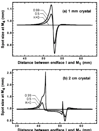
Using the cavity laser power as a parameter, we calcu-late the spot size at the output coupler as a function of the crystal location (varying r, with s 114.6 2 t 2 r). The results are shown in Fig. 7 for two different crystal thick-ness, 1 mm and 2 cm. We observe in Fig. 7(a) that the output spot size is constant for K 0. When the cavity power is larger than 0 a peak and a valley begin to grow on the spot size curve at near r 52 and r 53 mm, re-spectively, which is similar to the external z-scan curves. As the cavity laser power is increased, the peak-to-valley value is increased. In Fig. 7(b) we also find the ordinary
z-scan-like phenomena for a 2-cm-thick crystal under
lower cavity power conditionssK 0 and K 0.5d, but the distance between the peak sr 41.7 mmd and the valley sr 52.5 mmd is larger than that of the thin-ner crystal. As the cavity laser power is raised, we ob-serve two spikes superimposed on the spot size curve near
r 43.3 and r 51.3 mm; the spikes tend to increase
the output spot size. This spiking phenomenon has not been reported in other studies and can be observed only with thick Kerr materials under high intracavity power conditions.
To help us understand this peculiar phenomenon, we plot in Figs. 8(a) and 8(b), respectively, beam spot size variations throughout the ring cavity for r 43.3 and
r 51.3 mm, where the two spikes occur. Detailed spot
size variations inside the Ti:sapphire crystal are shown in Fig. 9. We note in Fig. 8 that the beam spot size varia-tions for high intracavity power K 0.99 are quite dif-ferent from those of lower powers K 0 and K 0.5. For K 0 and K 0.5, there is a Gaussian beam
Fig. 7. Output spot sizes in the intracavity z-scan analysis for various intracavity laser powers. The optical distance between the curved mirrors is 114.6 mm. (a) 1-mm Ti:sapphire crystal; (b) 2-cm Ti:sapphire crystal.
Fig. 8. Calculated spot size throughout the laser cavity for (a) r 43.3 mm and (b) r 51.3 mm as functions of the distance from endface I under various cavity power conditions. The Ti:sapphire rod is 2 cm long.
waist in the region from M1 by way of M3 and M4 to
M2; however, there is no beam waist in this region for
K 0.99. This suggests that the focusing power of this
2-cm Ti:sapphire crystal should be comparable with ei-ther of the curved mirrors at this high intracavity power, such that the mode distribution inside the cavity is drasti-cally changed. Under this circumstance the self-focusing action moves the position of the Gaussian beam waist between the curved mirrors too close to one of these mirrors. This is confirmed by Fig. 9. We observed in Fig. 9 that the positions of the Gaussian beam waist in-side the Ti:sapphire crystal are almost unchanged for lower powers K 0 and K 0.5. However, at the high intracavity power K 0.99 the beam waist is shifted outside the crystal and becomes too close to one of the curved mirrors. Recall that when an object is placed in front of a positive lens and the separation is less than the focal length then there is no real image be-hind the positive lens. This explains why spikes occur. However, if the Ti:sapphire crystal is placed too close to one of the curved mirrors, the laser power intensity is not high enough to promote the focusing power of the crystal to be comparable with that of either of the curved mirrors. Alternatively, if the Ti:sapphire crystal is placed near the center of the curved mirror pair, both self-focusing and self-defocusing will occur inside the crystal. The beam waist is still near the center of the curved mirror pair, not close enough to either of the curved mirrors to alter the Gaussian modes in the cavity drastically. For a thin Ti:sapphire crystal the focusing power is much smaller than those of the curved mirrors, and the spiking phenom-enon will not happen. Owing to the possible existence of
Fig. 9. Calculated spot sizes inside the Ti:sapphire crystal for (a) r 43.3 mm and (b) r 51.3 mm as functions of distance from endface I under various cavity power conditions.
these spikes, one must be very careful in analyzing the
z-scan data if an extremely high-power laser is used in
the measurement of the nonlinear refractive index n2.
6.
CONCLUSIONS
In this paper we introduced a novel and simple analytical approach to the study of Kerr-lens mode-locked ring cav-ity lasers. When the self-similar point in the cavity is properly chosen, the order of the equations for Gaussian-beam curvature is reduced by a factor of 2, and the prob-lems for the Gaussian-beam curvature and the spot size throughout the nonlinear cavity are reduced to quadratic equations. Since the q parameters throughout the laser cavity can be analytically expressed as functions of cav-ity parameters and astigmatism-compensation angles, it becomes much easier to design KLM lasers with the help of this method. We suggest that the astigmatism is best compensated so that the stable range of x and y directions have the best overlap (see Fig. 3). Although to maximize the hard-aperture effect one must configure the cavity parameters such that the curved-mirror separation is lo-cated at the far edge of stable range, pump and cavity field matching inside the Kerr medium is also necessary. In addition, insertion of a vertical slit at M1is more
effec-tive than insertion of a horizontal slit (see Fig. 4). Our recently constructed KLM Ti:sapphire laser demonstrates the possibility of self-starting and self-mode-locking with a properly coinciding pumping beam waist and KLM cav-ity beam waist.17 In surveying the intracavity z-scan
properties, we have found a spiking phenomenon caused by drastic alteration of Gaussian modes in the cavity as a result of the competition of the focusing power of the
Kerr medium and that of the curved mirrors under the conditions that the Kerr material is thick and the intra-cavity power is high. One must be careful in analyzing the z-scan data if an extremely high-power laser is used in the measurement of the nonlinear refractive index. Be-cause the intracavity laser power is much higher than extracavity laser power, the sensitivity of the intracav-ity z-scan measurement of the nonlinear refractive index and absorption should be much better than that of the external z-scan method.
APPENDIX A
Here we prove the transformation reversibility of the renormalized q parameter in the positive and the negative
z directions. See Fig. 1; the positive direction is defined as that from endface II to endface I. Let the q parameter at endface I be 1yqI 1yRI2 js1yyId. Recall that from
Eq. (9), by transformation of qIthrough the Kerr medium
for a beam propagating in the negative z direction, the q
parameter at endface II is 1 qII f yI2RI2 LyI22 LRI2s1 2 Kdg 2 jyIRI2 yI2RI22 2LyI2RI1 L2yI21 LRI2s1 2 Kd . (A1)
To show the transformation reversibility, we further transform qIIthrough the Kerr medium to endface I in the
positive z direction and test whether the final q parameter is equal to 1yqI 1yRI2 js1yyId. We first renormalize
qII as 1 qII0 f yI2RI2 LyI22 LRI2s1 2 Kdg 2 jyIRI2 p 1 2 K yI2RI22 2LyI2RI1 L2yI21 LRI2s1 2 Kd . (A2) With the renormalized q parameter transformed through the Kerr medium by means of matrix
" 1 L
0 1 #
,
the q0 parameter at endface I is
qI0 1yqII0 1 1 Ls1yqII0d fyI2RI2 LyI22 LRI2s1 2 Kdg 2 jyIRI2 p 1 2 K yI2RI22 2LyI2RI1 L2yI21 LRI2s1 2 Kd2. 1 1 LfyI 2R I2 LyI22 LRI2s1 2 Kdg 2 jyIRI2 p 1 2 K yI2RI22 2LyI2RI1 L2yI21 LRI2s1 2 Kd .
After some careful arithmetic manipulation, we have
qI0 1 RI " 1 2 2 L RI 1 L 2 RI2 1 L 2 yI2s1 2 Kd # 2 j p 1 2 K yI " 1 2 2 L RI 1 L 2 RI2 1 L 2 yI2s1 2 Kd # 1 2 2 L RI 1 L 2 RI2 1 L 2 yI2s1 2 Kd 1 RI 2 j p 1 2 K yI .
Then, by applying inverse q-parameter renormalization to qI0 we get 1yRI2 js1yyId, which is exactly the same
as qI. Therefore the approach used in the derivation of
Eqs. (10) and (11) is equivalent to that of transforming the q parameter from endface II, via the Kerr medium, by way of M1, M3, M4, M2, back to endface II, which is
always in the positive direction.
ACKNOWLEDGMENTS
We gratefully thank Chin Der Hwang of the Institute of Electro-Optical Engineering for useful discussion. This research is supported in part by the National Science Council, Taiwan, under grant NSC82-0208-M009-068.
REFERENCES
1. D. E. Spence, P. N. Kean, and W. Sibbett, “60-fsec pulse generation from a self-mode-locked Ti:sapphire laser,” Opt. Lett. 16, 42 (1991).
and M. M. Murnane, “Generation of 11-fs pulses from a self-mode-locked Ti:sapphire laser,” Opt. Lett. 18, 977 (1993). 3. P. F. Curley, Ch. Spielmann, T. Brabec, F. Krausz,
E. Wintner, and A. J. Schmidt, “Operation of a femtosecond Ti:sapphire solitary laser in the vicinity of zero-group-delay dispersion,” Opt. Lett. 18, 54 (1993).
4. W. S. Pelouch, P. E. Powers, and C. L. Tang, “Self-starting mode-locked ring-cavity Ti:sapphire laser,” Opt. Lett. 17, 1581 (1992).
5. G. W. Pearson, C. Radzewicz, and J. S. Krasinski, “Analysis of self-focusing mode-locked lasers with additional highly nonlinear self-focusing elements,” Opt. Commun. 94, 221 (1992).
6. D. Georgiev, J. Herrmann, and U. Stamm, “Cavity design for optimum nonlinear absorption in Kerr-lens mode-locked solid-state lasers,” Opt. Commun. 92, 368 (1992).
7. T. Brabec, Ch. Spielmann, P. E. Curley, and F. Krausz, “Kerr lens mode locking,” Opt. Lett. 17, 1292 (1992).
8. D. R. Heatley, A. M. Dunlop, and W. J. Firth, “Kerr lens effects in a ring resonator with an aperture: mode locking and unidirectional operation,” Opt. Lett. 18, 170 (1993). 9. V. Magni, G. Cerullo, and S. D. Silvestri, “ABCD matrix
analysis of propagation of Gaussian beams through Kerr media,” Opt. Commun. 96, 348 (1993).
10. H. A. Haus, J. G. Fujimoto, and E. P. Ippen, “Analytic
the-ory of additive pulse and Kerr lens mode locking,” IEEE J. Quantum Electron. 28, 2086 (1992).
11. K.-H. Lin and W.-F. Hsieh, “An analytical design of symmet-rical Kerr-lens mode-locking laser cavities,” J. Opt. Soc. Am. B 11, 737 (1994).
12. D. Huang, M. Ulman, L. H. Acioli, H. A. Haus, and J. G. Fujimoto, “Self-focusing-induced saturable loss for laser mode locking,” Opt. Lett. 17, 511 (1992).
13. H. W. Kogelnik, E. P. Ippen, A. Dienes, and C. V. Shank, “Astigmatically compensated cavities for cw dye lasers,” IEEE J. Quantum Electron. QE-8, 373 (1972).
14. B. E. Lemoff and C. P. J. Barty, “Generation of high-peak-power 20-fs pulses from a regeneratively initiated, self-mode-locked Ti:sapphire laser,” Opt. Lett. 17, 1367 (1992). 15. A. Stingl, C. Spielmann, F. Krausz, and R. Szip¨ocs,
“Genera-tion of 11-fs pulses from a Ti:sapphire laser without the use of prisms,” Opt. Lett. 19, 204 (1994).
16. M. Sheik-Bahae, A. A. Said, T. -H. Wei, D, J. Hagan, and E. W. Van Stryland, “Sensitive measurement of optical non-linearities using a single beam,” IEEE J. Quantum Electron.
26, 760 (1990).
17. J.-M. Shieh, F. Ganikhanov, K.-H. Lin, W.-F. Hsieh, and C.-L. Pan, “Completely self-starting picosecond and fem-tosecond Kerr-lens mode-locked Ti:sapphire laser,” J. Opt. Soc. Am. B (to be published).