The First Order Optics of Novel Testing Equipment for Compact
Camera Module
Jui-Wen Pan
Institute of Photonic System, National Chiao Tung University, Tainan, Taiwan 71150, R. O. C.
*Corresponding author:juiwenpan@gmail.com
ABSTRACT
We proposed a modified testing equipment for adjusting the back focal length of compact camera module (CCM). The advantages of this modified testing equipment with conversion lens were testing space saving, small size testing chart, high speed chart changing, and variable object distances. The testing chart displacement of 0.17 mm in the modified testing equipment can produce the equivalent testing chart displacement of 1000 mm in the conventional testing equipment. At the regular object distance of 2000 mm, both total track and testing chart size of the modified test equipment were 1.6% of that of the conventional testing equipment.
Keywords: compact camera module, magnification, reduction ratio, CMOS sensor.
1. INTRODUCTION
The mini size and the portable electron devices such as the mobile phone and the personal digital assistant (PDA) become popular consuming electronic devices especially for the time management and the information communication. An essential element of those consuming electronic products was the imaging device. In order to assemble the imaging device into those consuming electronic devices, the imaging and sensing component were packaged in a compact size module called compact camera module (CCM). The CCM is consisting of complementary metal-oxide-semiconductor (CMOS) sensor, lens holder and pick-up lens. Because the CCM had characteristics such as inexpensive cost, compact volume and simple structure, the CCM was widely applied to web camera and mobile phone. However, due to the simple structure of CCM, the dynamic focus compensation mechanism such as voice coil motor (VCM) and liquid lens was not existed in the CCM [1-3]. Thus, the accuracy alignment between pick-up lens and imaging sensor was an important issue in CCM assembling.
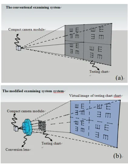
The current examination method of CCM assemble was shown in Fig. 1(a). A testing chart localized in front of the pick-up lens and then the image quality on CMOS sensor was used to judge that if the CMOS sensor assembled on the back focal plane of pick-up lens. If the back focal length between the CMOS sensor and pick-up lens cannot be assembled precisely, the caught image quality was blurred. The blurred image impacted the yield of CCM mass
production. Generally, the object distance of CCM used in mobile phone was varied from 200 mm to 5000 mm. At this object distance varying rang, the size of testing chart changed from 234 mm ×176 mm to 5960 mm × 4470 mm. The testing chart moved along the normal direction of CCM for assemble quality examination. Thus the volume of this conventional testing equipment was large and the testing chart fabrication cost was expensive. A solution for reducing the examining equipment volume was the insertion of a folding mirror in the imaging path that can reduce the horizontal space. However, the vertical space was increased simultaneously by this folding mirror. Because the total track of optical path was a constant for an image pick-up system under the conjugation relation between object and image. Besides, the folding mirror also increased the equipment cost and then induced alignment issues in the mass examination process. In other words, the conventional examining equipment remained an over large volume problem to be improved.
Modified examining equipment proposed by our group was shown in Fig. 1(b). The conversion lens was inserted to this modified examining equipment to produce an erect virtual image. This erect virtual image was used to be the new testing chart of the modified examining system. After the conversion lens insertion, the modified examining equipment possessed a short examining period and a compact size to improve the mass production technique of CCM.
2. SIMULATION
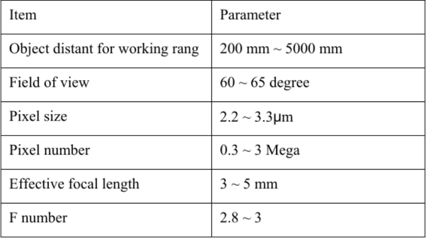
The specifications of this conversion lens must follow the CCM specifications for the back focal length examination. The common specifications of CCM briefly were described in table 1 [4]. The CCM with effective focal length of 4.16 mm and field of view of 65 degree was adopted as our conversion lens design conditions. The effective focal length of the proposed conversion lens was selected at 60 mm. In the modified examining equipment, the conversion lens played a role of magnifying lens [5].
Table 1 the commercial compact camera module’s specification
Item Parameter Object distant for working rang 200 mm ~ 5000 mm
Field of view 60 ~ 65 degree
Pixel size 2.2 ~ 3.3μm
Pixel number 0.3 ~ 3 Mega
Effective focal length 3 ~ 5 mm
F number 2.8 ~ 3
The work principle of proposed modified examining equipment can be illustrated by the paraxial optics layout. The paraxial optics was an estimate for optical system design. The paraxial optics equation of this conversion lens was derived as following.
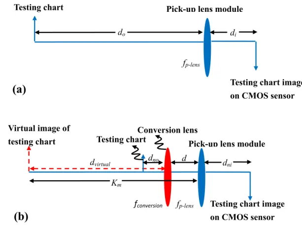
Fig. 2 shows the paraxial optical layout of two testing equipments. Fig. 2(a) illustrates the paraxial optical layout of the conventional equipment. The Eq. (1) describes the object and image relation followed the lens maker equation.
lens p i o
d
f
d
+
=
−1
1
1
Eq. (1)The testing chart was located in front of pick-up lens with distance do. The distance between the pick-up lens and
CMOS sensor was labeled di. In the conventional examining equipment, do and di were object and image distance,
respectively. The imaging distance was also named back focal length of the pick-up lens. The effective focal length of the pick-up lens is fp-lens. During examining process, the testing chart was imaged at the CMOS sensor. If the CMOS
sensor was not assembled at the image distance precisely, the testing chart image on the CMOS sensor was blurred. By adjusting the back focal length correctly, the image quality on the CMOS sensor became a criterion.
The modified examining equipment is shown in Fig. 2(b). A conversion lens was inserted between CCM and testing chart with distance d in front of CCM. At this paper, the distance d was set as 20 mm. The effective focal length of conversion lens was 60 mm labeled in fconversion. The testing chart became an object of the inserted conversion lens
with object distance dno and then this conversion lens introduced an erect virtual image of real chart at the distance of
dvirtual from the conversion lens. The relation between dno and fconversion is shown in Eq. (2)
conversion virtual o n
d
f
d
1
1
1
+
=
Eq. (2)Because the dno was smaller than fconversion in the modified examining equipment, the image of testing chart was
magnified, erect and virtual at dvirtual. The working rang of dvirtual can be any number in the right side of the conversion
lens [5].
Fig. 2 The first order layout of the (a) conventional and (b) modified examining system
The modified examining equipment adopted this erect virtual image at dvirtual as a new object to replace the real
testing chart used in conventional testing equipment. The new object distance of the modified examining equipment was
Km that equaled the summation of dvirtual and d. The image distance of this modified examining equipment was dni. Both
Km and dni obeyed lens maker equation as shown in Eq. (3).
lens p ni m
d
f
K
+
=
−1
1
1
where
K
m=
d
virtual+
d
Eq. (3)Pick-up lens module
Testing chart image
on CMOS sensor
f
p-lensVirtual image of
testing chart
d
ni(b)
K
md
virtualTesting chart
Conversion lens
f
conversiond
d
noPick-up lens module
f
p-lensd
iTesting chart
d
oTesting chart image
on CMOS sensor
Since the image produced by the conversion lens located at the left side of the conversion lens, the dvirtual was
native negative by optical definition [5, 6]. Thus an absolute value process was necessary for the calculation of new object distance.
Because the value of Km in the modified equipment was identical to the value of do in the conventional equipment,
the Eq. (2) was adopted to obtain the relationship between do and dno as Eq. (4).
conversion o o conversion no
f
d
d
d
d
f
d
−
−
−
×
=
)
(
)
(
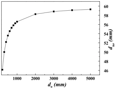
Eq. (4)According to Eq. (4), the relation curve between dno and do was plotted in Fig. 3. In Fig. 3, the dno was 59.28 mm
in the modified examining equipment that can produce a virtual image. This virtual image equaled the testing chart located at do that equaled 5000 mm in the conventional examining equipment. The object distance in modified examining
equipment was 1.18% of the object distance in conventional examining equipment.
1000 2000 3000 4000 5000 46 48 50 52 54 56 58 60
d
no(mm)
d
o(mm)
Fig. 3. The relation between object distant of the conventional examining system (do) and the modified examining
system (dno).
The testing chart in the conventional examining equipment moved form 5000 mm to 4000 mm in do for the
examination for back focal length. Contrary, in the modified examining equipment, the testing chart just moved from 59.11mm to 59.28 mm in dno. The conversion lens reduced the testing chart displacement to 0.01% in the modified
examining equipment. For a constant testing chart moving rate, the short moving range of the modified testing equipment provided a high throughput. The testing chart can also be changed faster than the conventional testing equipment. Furthermore, the different object distances were varied in the modified testing equipment to produce the different virtual
object distance for CCM. This modified examining equipment possessed two advantages. One was high speed testing chart changing and the other was the variable virtual object distance achieved by the small shift in the object distance of the testing chart.
3. ANALYSIS
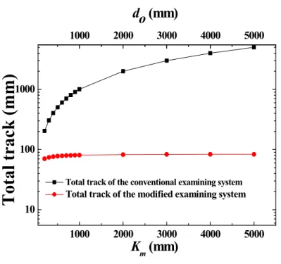
Fig. 4 represents the total track of the conventional and modified examining equipments. The total track of the conventional examining equipment was the summation of do and di and the total track of modified testing equipment was
the summation of dno, d and dni. The black curve showed the total track versus do while the red curve showed the total
track versus Km. For the conventional testing equipment, the total track approached the value of do owing to do was much
larger than di. Thus the total track of the conventional examining equipment varied from 200 to 5000 mm in the real
space. In the case of the modified examining equipment, the different Km was obtained while the total track was seldom
changed. Thus the total track of the modified examining equipment was about 84mm. Comparing to the convention examining equipment volume at object distant, do, of 2000 mm, volume of the modified examining equipment was
reduced to 1.6%. 1000 2000 3000 4000 5000 10 100 1000 1000 2000 3000 4000 5000
do (mm)
Total track (mm)
K
m(mm)
Total track of the conventional examining system Total track of the modified examining system
Fig. 5 also illustrated that the total track yield was more efficient in the modified examining equipment than the conventional one in different object distance testing. Thus the volume of the modified examining equipment was significantly reduced by the insertion of the conversion lens.
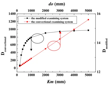
0 1000 2000 3000 4000 5000 0 200 400 600 800 1000 1200 14000 1000 2000 3000 4000 5000 12 14 16
D
co nv ect ionalKm (mm)
the modified examining system the convectional examining systemdo (mm)
D
modified
Fig. 5. The relation between object distance (do) and reduction ratio (Dconventional)of the conventional examining
system. The relation between Km and reduction ratio (Dmodified) of the modified examining system.
Another important feature of the conversion lens was the reduction ratio. The reduction ratio was defined as the reciprocal of the magnification of the optical system. According to the definition of magnification [7], reduction ratio of the conventional testing system and the modified testing system were stated as Eq. (5) and Eq. (6).
i o al convention al convention
d
d
M
D
=
−
1
=
−
Eq. (5) ni m virtural no ified ifiedd
K
d
d
M
M
M
D
=
−
=
−
=
−
2 1 mod mod1
1
Eq. (6)Dconventional and Dmodified were the reduction ratio of the conventional examining equipment and the modified
examining equipment. Mconventional and Mmodified were the magnification of the conventional examining equipment and the
modified examining equipment. The M1 was the magnification for the conversation lens and the M2 was the
magnification for the pick-up lens with virtual image introduced by the conversion lens.
For the imaging quality testing of CCM, the line pair chart was an important method [7-9]. The line pair chare have a relationship with modulation transform function (MTF) by magnification and reduction ratio [10, 11]. According
to the Eq. (5) and Eq. (6), the reduction ratios of two systems versus different object distances were shown in Fig. 5. The reduction ratio of modified examining equipment varied at the range between 12 and 15 while that of the convectional examining system varied at the range between 14 and 1300. The reduction ratio of the modified examining system was only 1.1% of that of the convectional system while Km when do were 5000 mm. Compared to the convectional examining
system, the reduction ratio of the modified examining system varied with a small dynamic range. Thus the geometric scale for the conventional examining system was varied rapidly. The line pair patterns used to judge the lens quality was shifted with the change of reduction ratio and magnification. Thus the feature for small variation in reduction ratio allowed the modified examining equipment to execute the through focus MTF examination by the same testing chart with fixed line pair pattern. For the conventional examining equipment, the MTF measurement through focus testing cannot be completed by the same testing chart because the reduction ratio changed rapidly with the object distances as shown in Fig. 5. Thus a serial of line pair patterns must be prepared for MTF measurement by the conventional examining equipment. The additional testing charts made the conventional examining equipment measurement difficult, complex and expensive. The modified examining equipment needed only one chart for the through focus MTF measurement. This advantage was very useful for wafer level lens testing under wavefront coding technology [12].
Finally, the modified testing equipment offered a lower cost and a simple method to achieve the thought focus MTF measurement.
4. CONCLUSION
In this paper, a modified examining equipment was proposed by insertion a conversion lens into the conventional examining equipment for the CCM examination. Comparing to the conventional examining equipment, the modified examining equipment possessed several advantages such as a simple structure, a compact volume, a fast examining rate, and a cost reduction. The modified examining equipment structure was quite simple because only one conversion lens was inserted. The compact volume was obtained by the virtual image produced by the conversion lens. This virtual image was adopted to be the new object in the modified examining equipment so that the total track of this modified examining equipment was 1.6% of the conventional examining equipment at object distance do of 2000 mm. The fast
examining rate was achieved by the small shift in dno introduced a large shift in Km so that the pick-up lens examination
was completed with variant object distances in a short time. Further the size of testing chart in modified examining equipment was only 1.6% of size of the testing chart used in the conventional equipment. This modified examining equipment also possessed 1% reduction ratio that can use one testing chart to complete the through focus test. Thus the cost of the modified examining equipment was significantly reduced.
ACKNOWLEDGEMENTS
REFERENCES
[1]C.S. Liu and P. D. Lin, “A miniaturized low-power VCM actuator for auto-focusing applications,” Optics Express, Vol. 16 Issue 4, pp.2533-2540 (2008)
[2]C.S. Liu and P. D. Lin, “Miniaturized auto-focusing VCM actuator with zero holding current,” Optics Express, Optics Express, Vol. 17 Issue 12, pp.9754-9763 (2009).
[3]S. Norio; M. Shinz,”Variable-focus liquid-filled optical lens,” Applied Optics, Vol. 32 Issue 22, pp.4181-4186 (1993) [4]Largan Precision Co. Ltd. “Conventional compact camera module specification,”
http://www.largan.com.tw/products_cellphone_en.htm
[5]E. Hecht “Lenses” in Optics Fourth Edition (Addision Wesley 2002) pp.162
[6]W. J. Smith, “Imaging formation (First-Order Optics),” in Modern Optical Engineering Third Edition, (McGraw- Hill, 2000) pp. 24 – 27
[7]W. J. Smith, “Basic Optical Device,” in Modern Optical Engineering Third Edition, (McGraw- Hill, 2000) pp. 253 – 255
[8]W. J. Smith, “Image Evaluation,” in Modern Optical Engineering Third Edition, (McGraw- Hill, 2000) pp. 366 – 385 [9]R. E. Fisher and B. Tadic-Galeb, “Computer Performance Evolution,” in Optical System Design, (McGraw- Hill, 2000) pp.193-201
[10]W. J. Smith, “Optics in Practice,” in Modern Optical Engineering Third Edition, (McGraw- Hill, 2000) pp. 592 – 596
[11]R. E. Fisher and B. Tadic-Galeb, “Tolerancing and Producitbility,” in Optical System Design, (McGraw- Hill, 2000) pp.347-356
[12]E. R. Dowski and W.T. Cathey, "Extended Depth of Field Through Wavefront Coding," Applied Optics, 34, 1859-1866 (1995)