Minimum Relevant Error MIMO Decision-Feedback Equalizer for High-Speed
Wireless Data Communications
Cheng-Kang Wang Yumin Lee
Graduate Institute of Comm. Eng. And Dept. of Electrical Eng., National Taiwan University
Taipei 10617, Taiwan Abstract
-A new criterion for optimizing the coefficients of
multi-input multi-output (MIMO) decision feedback equalizers (DFE) is proposed for asymmetric signal constellations. It is shown that the new criterion is a generalization of the minimum mean-square error (MMSE) criterion. The proposed MIMO DFE can be applied to the equalization of Gaussian minimum shift keying (GMSK) signals. Simulation results indicate that the proposed method achieves a performance gain of as much as 2dB without increasing equalization complexity.
I. INTRODUCTION
Multi-user wireless communications suffer from signal fading and inter-symbol interference (ISI) caused by multipath propagation, as well as multiple-access interference (MAI) caused by other users. Multiple-input multiple-output (MIMO) signal processing is a powerful technique for simultaneously tackling these problems and improving the performance of wireless communication systems. Consider a wireless communication system in which signals from K (K ≥ 1) users are transmitted simultaneously, and assume that D (D ≥ 1) receivers are available at the output of channel. The samples of the received signals are processed using an MIMO signal processor with D inputs and K outputs that is designed to jointly detect the transmitted data symbols of all users. Theoretically, the optimal (maximum likelihood) receiver is in the form of the multi-channel maximum likelihood sequence estimator (MLSE). However, since the complexity of MLSE is very high, many receivers use sub-optimal symbol-by-symbol detection rather than sequence estimation. One common receiver structure is the MIMO decision feedback equalizer (DFE), which linearly combines received signal samples and past decisions to reduce the effect of ISI and MAI. Coefficients of DFE need to be chosen carefully in order to achieve good performance, and one popular optimization criterion is the minimum mean square error (MMSE) criterion [2-4]. The MMSE criterion is very popular due to its simplicity and good performance. However, as will be shown later in this paper, because of the way in which it is formulated, the MMSE MIMO DFE is more suitable for signal constellations that are circularly
symmetric. For asymmetric constellations, therefore, we
propose a novel generalization of the MMSE criterion referred to as the minimum relevant error (MRE) criterion. The proposed MRE criterion can greatly enhance the performance of the DFE when the signal constellation is asymmetric, and degenerates into the conventional MMSE criterion when the signal constellation is circularly symmetric.
In this paper, we also demonstrate a novel way to use the MRE DFE for equalizing Gaussian minimum shift keying (GMSK) signals. Simulation results show that significant performance gain is achievable using the proposed method without increasing equalization complexity (number of multiplications and additions per symbol-period). In fact, for the case simulated, the MRE DFE outperforms the conventional MMSE DFE by as much as 2 dB, and is only a fraction of a dB away from the matched filter bound (MFB).
II. THE MIMO SIGNAL MODEL
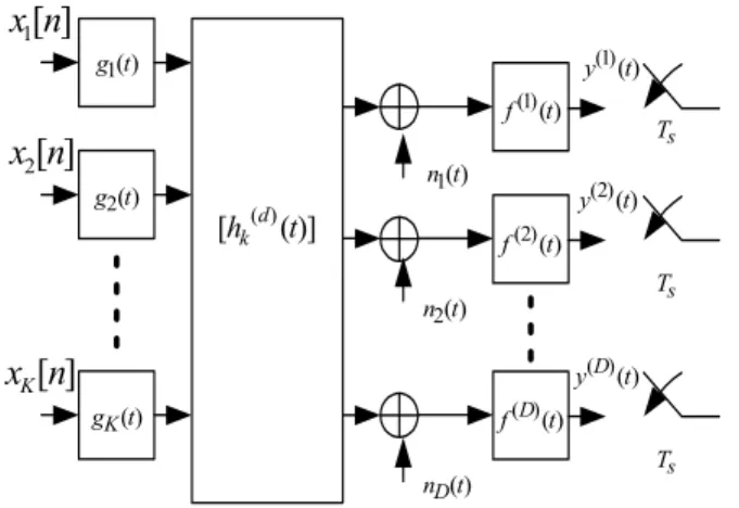
Consider the baseband-equivalent model of an MIMO transmission system shown in Fig. 1. Assuming that K users transmit simultaneously over a common medium, the baseband-equivalent transmitted signal for the k-th (k =1,2,…,
K) user is given by
[ ]
∑
− = n k k k t x ng t nT u () ( ), (1) where1 xk[n] and gk(•) are the n-th symbol and pulse-shaping function of the k-th user, respectively, and T is the symbol-period. There are D antennas at the receiver, each being followed by a receiver filter with impulse response f (d)(t), d = 1,2,…, D. We assume that the medium between the k-th user and the d-th antenna is a linear and time-invariant system corrupted by additive white Gaussian noise (AWGN). The received signals y(d)(t), d = 1,…, D, are next sampled at a rate) ( 1t g ) ( 1t n ) ( ) 1 ( t f
]
[
1n
x
]
[
2n
x
]
[n
x
K ) ( 2t g ) (t gK )] ( [hk(d) t ) ( 2t n ) (t nD s T s T s T ) ( ) ( t fD ) ( ) 2 ( t f ) ( ) ( t yD ) ( ) 2 ( t y ) ( ) 1 ( t yFig. 1. The MIMO system model.
of L samples per symbol period. The L signal samples during one symbol period at the output of each of the D receiver filters can be stacked into L×1 polyphase vectors y(d)[n]. These D poly-phase vectors can be further stacked into an
1 ×
LD received signal super vector given by
[
T DT]
T n n n] [ ] [ ] [ y(1) y( ) y = L . (2) Similarly, the transmitted symbols of the K users can be stacked into a K×1 column vector x[n]. Then we have[
]
[ ] ] [ ] 1 [ ] [ ] [ ] 1 [ ] 0 [ ] [ n n n n v n n x x x p p p y + − − = ν M L , (3)where p[n] is an LD × K matrix function of the transmitter filter, channel, are receiver filter, and n[n] consists of the filtered Gaussian noise samples.
The received signal super vector y[n] is next processed by the MIMO DFE shown in Fig. 2. The MIMO DFE consists of the feedforward filter (FFF), feedback filter (FBF), and slicer. The FFF and FBF are finite-impulse-response (FIR) multi-channel filters with Nf and Nb matrix coefficients, respectively, and both output K × 1 vectors. Input to the FFF and FBF are y[n] and vectors of past decisions, respectively. The output of the DFE at time n is a K × 1 vector equal to the sum of the output of FFF and FBF, and is given by
∑
∑
= − = − + − ∆ + = b f N i H i N i H i n i n i n 1 1 0 ] [ ˆ ] [ ] [ w y b x z , (4)where wi, i = 0,1,…,Nf –1 are the (LD) ×K FFF coefficient
∑
] [n+∆ y I 1 − z z−1I I 1 − z I 1 − z ] 1 [n+∆−Nf+ y H 0 w wNf−1H H 1 b ] [n z xˆ n[ ] ] 1 [ ˆn− x I 1 − z H Nb b ] [ ˆn−Nb xFig. 2. The MIMO-DFE.
matrices, bi, i = 1,…,Nb are the K×K FBF coefficient matrices, “H” denotes Hermitian transposition, ∆ is the decision delay, and xˆ
[ ]
n−i is a K × 1 vector of detected symbols at time n – i. The output z[n] is then fed into the slicer to obtain thedetected symbol vector xˆ
[ ]
n .III. THE MINIMUM RELEVANT ERROR MIMO DFE In the MIMO DFE shown in Fig. 2, the coefficient matrices wi and bi must be chosen carefully in order to achieve good performance. Conventionally, the MIMO DFE is optimized using the MMSE criterion, i.e., the matrices wi and bi are chosen such that the quadratic form cHΣΣΣΣc is minimized for every nonzero K × 1 vector c, where
[ ] [ ]
(
)
(
[ ] [ ]
)
[
n n n n H]
E x z x z
Σ≡ − − (4)
is the error covariance matrix of the MIMO DFE. In particular, for an MMSE MIMO DFE the error variances of the users, given by
[
]
[
]
(
)
[
2]
[
(
[
]
)
2]
2 2 ] [ ] [ Im ] [ ] [ Re ] [ ] [ n z n x E n z n x E n z n x E k k k k k k k − + − = − ≡ σ (5)for k = 1, …, K, are minimized simultaneously. For the case where xk[n] is circularly symmetric2, it can be shown that
E[(Re[xk[n] – zk[n]]2) = E[(Im[xk[n] – zk[n]]2), thus the error variances of both in-phase and quadrature-phase components of the k-th user are minimized at the same time. For symbols in a circularly symmetric constellations (e.g. quadrature
phase-shift keying and quadrature amplitude modulation), the in-phase and quadrature-phase components are equally important, thus the MMSE criterion is highly desirable. However, many commonly used signal constellations are not circularly symmetric. Binary phase shift keying (BPSK) symbols, for example, convey information only in one of the in-phase and quadrature phase components3, and is therefore asymmetric. Intuitively, the signal processing power of the MIMO DFE should not be wasted on minimizing the error in the irrelevant component. It is therefore more desirable to minimize the error in the relevant (in-phase or quadrature-phase) component of the k-th user, instead of minimizing σk2 (which is the sum of the in-phase and quadrature-phase errors), when asymmetric constellations such as BPSK are used.
We thus propose the following minimum relevant error (MRE) criterion for MIMO DFE optimization. Assuming that the in-phase component is relevant for users 1,2, …, K1 and quadrature-phase component is relevant for users
K1+1, …, K. The FFF and FBF coefficients are chosen such that E[(Re[xk[n] – zk[n]]2), k = 1,2,…, K1, and E[(Im[xk[n] –
zk[n]]2), k = K
1+1,…, K are minimized simultaneously. It can be shown that the MRE MIMO DFE coefficients can be obtained by solving the system of linear equations given by
+ Σ + Σ = Σ + Σ × − ∆ − + × ∆ × − ∆ − + × ∆ B W R P P B W J P P 0 J 0 0 I 0 P N X X X X ) ~ ~ ( ~ ~ ~ ~ * * ) 1 ( ) 1 ( H T K K N K K K K N K K f f ν ν , (6)
where W is the NfLD× K matrix of FFF coefficients, B is the
NbK × K matrix of FBF coefficients, “*” denotes complex
conjugation of every element of a matrix, I is the K × K
identity matrix, J is a K × K diagonal matrix whose first K1
diagonal elements are 1 and the remaining diagonal elements are –1, ΣX is the complementary covariance matrix of X
defined as
[ ]
TE XX
X=
Σ , (7) 0a,b is an a × b block of zeros,
3 We refer to the component that conveys information as the relevant
component. = − ∆ − − + × × + ∆ ×(( 1) ) ( ) ) ( 1) ) ( ~ b f b b b bK K NK NK NK N N N I 0 ν 0 P P (8) in which = ] [ ] 1 [ ] 0 [ ] [ ] 1 [ ] 0 [ ] [ ] 1 [ ] 0 [ ν ν ν p p p p p p p p p P L O O O O L L , (9) and
[
H]
n n EN N RN~ = ~ ~ (10) in which = ×1 ~ K N n n b 0 N N (11) and + − − = ] 1 [ ] 1 [ ] [ f n N n n n n n n N M . (12)Derivation of (6) is very tedious and is omitted due to space limitations. It should be noted that when xk[n] is circularly symmetric for all k, we have ΣX= and the MRE 0
MIMO DFE is the same as the MMSE MIMO DFE. Therefore the proposed MRE criterion is in fact a generalization of the MMSE criterion, and includes the MMSE criterion as a special case.
IV. APPLICATION TO GMSK
GMSK is a binary continuous phase modulation (CPM) scheme that is adopted in many wireless standards. Since GMSK is a nonlinear modulation scheme, its maximum likelihood detection requires phase-domain trellis search, which is difficult to implement especially in the presence of ISI caused by multipath fading channel [8]. Laurent [1] gave an exact decomposition of binary CPM signals into a sum of linearly modulated waveforms. Conventionally, practical GMSK equalizers are designed by retaining only the dominant term of Laurent’s decomposition and approximating GMSK as a linearly modulated signal. A single-input single-output (SISO) DFE or MLSE is then used to equalize the signal. In this section, we illustrate a novel way of applying the proposed MRE MIMO DFE in the equalization of a GMSK signal by formulating GMSK modulation as an equivalent MIMO transmission scheme. As
will be shown in the next section, significant performance gain is achievable using the method described in this section.
Consider a differentially encoded GMSK transmission system in which data bits d[n] are first differentially encoded and mapped onto α[i] ∈ {+1,-1}. The baseband-equivalent transmitted signal is given by [6]
[ ]
iq t iT nT t n T j A t s n i ) 1 ( , ) ( exp ) ( 0 + ≤ < − =∑
= α π , (13)where T is the symbol period as defined previously, and q(t) is the GMSK phase function. The signal s(t) is transmitted over the wireless channels (each modeled as a multipath propagation channel corrupted by AWGN) to D receiver antennas. The received signal at the d-th antenna is given by
) ( ) ( ) ( ( ) ( ) ( ) ( ) ) ( t s h f t n f t yd = ⊗ d ⊗ d + d ⊗ d , (14) where h(d)(t), d = 1, …, D is the impulse response of the
channel between the transmitter and the d-th antenna, f (d)(t) is
the impulse response of the receiver filter for the d-th antenna, and n(d)(t) is AWGN in the d-th channel. As mentioned
earlier, the GMSK signal s(t) can be closely approximated as
[ ]
(
)
∑
− ≈ n nT t c n b t s() 0 (15) where b[n] is the n-th pseudo symbol given by[ ]
(
[ ]
)
( )
+ − = 2 1 exp 1 2d n j n n b π . (16)and c0(t) is defined in [1]. It can be seen from (16) and (17) that GMSK can in fact be approximated as π/2-rotated BPSK signal pulse-shaped by c0(t). In particular, we can see that
[
n k]
(
t nT)
( )
t b t y kd d k n d 2 ( ) ( ) 1 ) ( ()≈∑∑
2 +2− β −2 +η = (17) where( )
t c(
t(
k)
T)
hd( )
t f d( )
t d k( ) = 0 − 2− ⊗ ( ) ⊗ ( ) β (18) and( )
t nd f d( )
t d) ( ) ( ) ( = ⊗ η . (19) We can see from (18) that the GMSK transmission system is equivalent to a MIMO transmission system with effective symbol-period 2T, K=2, x1[n]=b[2n+1], x2[n] = b[2n], g1(t) = c0(t-T), g2(t) = c0(t), and h1(d)(t) = h2(d)(t) = h(d)(t). Furthermore, since the in-phase (quadrature) component of b[n] is relevant for n odd (even), only the in- phase andquadrature components are relevant in x1[n] and x2[n], respectively. Thus the proposed MRE MIMO DFE with K1 = 1 can be used for GMSK, and (7) can be used to solve for the optimal (MRE) MIMO DFE coefficients using
S/P ) (t y L T 2 MIMO FFF ] [n+∆ y MIMO FBF bˆ n[ ] n even n odd
Fig.3 MRE MIMO-DFE for GMSK.
these parameters. The resulting structure is a D-input single-output DFE that uses two sets of jointly optimized coefficients. An example is illustrated in Fig. 3 for D=1. It should be noted that the two sets of coefficients are jointly optimized even though they are used for different symbols. This is because the ISI in any received signal sample is the contribution of both even and odd symbols. Therefore using two jointly optimized DFE’s as proposed in this paper achieves better performance than using two independently optimized DFE’s.
V. SIMULATION RESULTS
The performance of the proposed MRE MIMO DFE for GMSK equalization is evaluated by computer simulation. Only D=1 is simulated for simplicity, even though the proposed algorithm also applies to the general case. The modulator is a differentially encoded GMSK modulator. As shown in Fig. 3, the user data bits are first differentially encoded and modulated onto the carrier according to (14). The time-bandwidth product BbT set to 0.3. The channel is linear and time-invariant with impulse response4
( )
(
)
(
t t T)
t h 0.9 0.5 9 . 0 1 1 ) ( 2 + − + = δ δ . (20)At the receiver, the received signal is first filtered using a square-root raised cosine filter with 50% roll-off. The output of the receiver filter is then sampled at a rate of 1/T samples/s, and processed by the proposed MRE MIMO DFE. Note that the effective (MIMO) symbol-period of the transmission system is 2T as mentioned previously, therefore the sampling
4 Since only D=1 is simulated, therefore we omit the superscript (d) in this
rate of 1/T is equivalent to 2 samples/symbol-period, i.e., L = 2. The MRE MIMO DFE consists of Nf = 11 FFF coefficient matrices of dimension 2×2 and Nb = 4 FBF coefficient matrices of dimension 2×2. The decision delay is set to ∆ = Nf – 1. Since the effective symbol period for the MRE DFE is 2T, a total number of 11×2 = 22 and 4×2 = 8 complex multiplications are required every T seconds by the FFF and FBF, respectively. The performance of a conventional MMSE SISO DFE is also simulated as a baseline for comparison. The FFF and FBF of the conventional MMSE-DFE respectively consist of 22 and 8 T-spaced coefficients, and therefore has the same equalization complexity as the proposed MRE MIMO DFE.
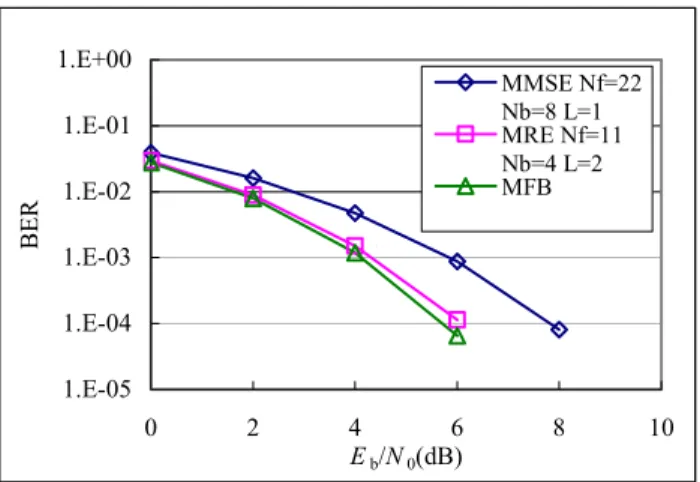
The simulation result is shown in Fig. 4, where the bit error rates (BER) of the MRE MIMO DFE and MMSE DFE and the matched filter bound (MFB) are shown as functions of Eb/N0, where Eb is the transmitted energy per bit and N0/2 is the two-sided power spectral density of the AWGN. From Fig. 4 we can see that the proposed MRE MIMO DFE achieves a performance gain of 2dB over the conventional MMSE DFE at BER around 10-4. Furthermore, performance of the MRE MIMO DFE is within a fraction of a dB from MFB. Since the MFB is the lower bound for uncoded BER, it can be inferred that the MRE MIMO DFE is near optimal (minimum BER).
VI. CONCLUSIONS
MMSE a popular criterion for optimizing MIMO DFE. The MMSE criterion minimizes the sum of the mean-square error in the real part and imaginary parts of its output, and is therefore more suitable for circularly symmetric signal constellations for which the in-phase and quadrature components are equally important. In this paper, the minimum relevant error (MRE) criterion is proposed for asymmetric signal constellations such as BPSK. It is shown that the MRE criterion is a generalization of the MMSE criterion, and in fact includes the MMSE criterion as a special case. The MRE can be applied to the equalization of GMSK signals. Simulation results show that, with the same equaliz ation complexity (number of multiplications and additions per symbol-period), a performance gain of as much as 2dB is achievable using the proposed method.
1.E-05 1.E-04 1.E-03 1.E-02 1.E-01 1.E+00 0 2 4 6 8 10 Eb/N0(dB) BER MMSE Nf=22 Nb=8 L=1 MRE Nf=11 Nb=4 L=2 MFB `
Fig. 4. The BER performance for equalizing GMSK with MRE MIMO DFE and MMSE SISO DFE in the channel defined in (20).
REFERENCES
[1] P. A. Laurent, “Exact and approximate construction of digital phase modulations by superposition of amplitude modulated pulses (AMP),”
IEEE Trans. Comm., vol. 34, pp.150-160, Feb. 1986.
[2] A. Duel-Hallen, “Equalizers for multiple input multiple output channels and PAM systems with cyclostationary input sequences,”
IEEE Journal on Selected Areas in Communivations, vol. 10, pp.
630-639, Apr. 1992.
[3] N. Al-Dhahir and J. M. Cioffi, “MMSE decision-feedback equalizers: finite length results,” IEEE Trans. Inform. Theory, vol. 41, pp. 961-975, July 1995.
[4] N. Al-Dhahir and A. H. Sayed, “The finite-length multi-input multi- output MMSE-DFE,” IEEE Trans. Signal Processing, vol. 48, No. 10, pp. 2921-2936, Oct. 2000.
[5] S. Haykin, Adaptive Filter Theory, Prentice Hall, 2nd edition, pp.782-
790.
[6] J.B Anderson, T. Aulin, C.-E. Sundberg, Digital Phase Modulation. New York:Plenum, 1986.
[7] J. H. Chen, Receiver Design And Simulation Analysis Of GPRS
Physical Layer, Master Thesis, National Taiwan University, June 2001.
[8] D. Dzung, “Receivers for CPM signals in frequency-selective multipath channels,” in Proc. 8th European Conf.