HARDWARE ARCHITECTURE DESIGN FOR VARIABLE BLOCK SIZE MOTION
ESTIMATION IN MPEG-4 AVC/JVT/ITU-T H.264
Yu- Wen Huang,
Tu-Chih
Wang, Bing-Yu Hsieh, and Liang-Gee
Chen
DSPlIC Design Lab
Graduate Institute
of
Electronics Engineering and
Department of Electrical Engineering, National Taiwan University
{yuwen, eric, bingyu, lgchen} @video.ee.ntu.edu.tw
ABSTRACT
Variable block size motion estimation is adopted in the new video coding standard, MPEG-4 AVCIIVTIITU-T H.264, due to its su- perior performance compared to the advanced prediction mode in MPEG-4 and H.263+. In this paper, we modified the reference software in a hardware-friendly way. Our main idea is to convert the sequential processing of each 8x8 sub-partition of a macro- block into parallel processing without sacrifice of video quality. Based on our algorithm. we proposed a new hardware architec- ture for variable block size motion estimation with full search at integer-pixel accuracy. The features of our design are 2-D pro- cessing element array with I-D data broadcasting and I-D partial result reuse, parallel adder tree, memory interleaving scheme, and high utilization. Simulation shows that our chip can achieve real- time applications under the operating frequency of 64.11MHz for 720x480 frame at 30 ti2 with search range of [-24, +23] in hori- zontal direction and [-16, +I51 in vertical direction, which requires the computation power of more than 50 GOPS.
1. INTRODUCTION
Video coding expens from I S 0 MPEG-4 Advanced Video Cod-
ing
(AVC) and ITU-T H.264 group form the Joint Video Team (JVT). The new techniques include motion estimation (ME) with variable block sizes and multiple reference frames, intra predic- tion, 2x2 and 4x4 transform, adaptive block size transform, non- uniform quantization. CAVLC, CABAC, in-loop deblocking filter, and more [I]. Compared to MPEG-4 advanced simple profile, up to 50% of bit-rate reduction can be achieved. However, the re- quired computation is more than four times higher. Therefore, hardware acceleration is a must for real-time applications, espe- cially for ME, which is the most computationally intensive pan.Many ME architectures have been proposed for previous stan- dards. Only one 16x16 block and four 8x8 blocks (advanced pre- diction mode in MPEG-4 simple profile and H.263+) could he used for motion compensation. They cannot fully support the seven kinds of block size (16x16, 16x8, 8x16, 8x8, 8x4, 4x8, and 4x4) in H.264. In addition, the reference software of H.264 121 adopts sequential processing of each 8x8 sub-partition. The data depen- dency between the sub-partilions makes parallel processing impos- sible. Thus, we must start the architecture design of variable block size ME for H.264 at the algorithmic level.
In this paper, we modify the reference software lo let the algo- rithm more suilable for hardware. In Section
2,
we first review theI I L I
Q1803-7761-31031P17.00 82003 IEEE
II-796
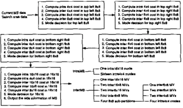
Figure I : Prediction flow in H.264 software.
prediction flow in lM4.M. In Section 3, we present our algorithm with experimental results of coding performance. Next, our archi- tecture, as well as the simulation results and comparison, will be described in Section 4 and Section 5 , respectively. Finally, Section
6 gives a conclusion.
2. PREDICTION FTOW IN H.264 SOFTWARE
Figure I shows the prediction flow of a 16x16 macro-block (MR) in H.264 software. The top left 8x8 block is first processed and followed by the top right 8x8, bottom left 8x8, bottom right 8x8, and 16x16. The mode decision considers not only the sum ofabso- lute difference (SAD) (2-D Hadamard transformed for intra modes and sub-pixel ME) but also the exact cost of side information. The entropy coding of intra modes depends on the context produced by the left and top neighbors. Resides, the intra prediction of a block cannot get the correct predictor until the neighboring blocks are quantized and then reconstructed. Moreover, the motion vectors (MVs) are medium predicted by the left. top, and top right neigh- bors. The cost function can be computed only after the modes of neighboring blocks are determined. Obviously, the methods in H.264 software cannot be used i n hardware implementation be- cause of the inevitable sequential processing resulted from the data dependency of neighboring blocks. The main problem comes from the "exact" cost of side information. In fact, it is the SAD. not the cost of side information, that dominates the total cost. It is not necessary to exactly calculate the cost of side information.
Y I W . 0 Y - r
P* rpmD
Figure 2: Modified prediction Row.
CII c12
H
Current Fnmr Rrrrrinrr F r "Figure 3: Overlapped search range of adjacent MBs. Each square
is 16x16 and assume search range is [-16, +16].
3. PROPOSED HARDWARE-ORIENTED ALGORITHM
Figure 2 shows the proposed hardware-oriented prediction Row. Full search ME is performed at integer search positions and s u b pixel refinement is next executed. The search range center is deter- mined by Ihe MV predictor in H.264 software. but we use (0.0) as center in order to share the overlapped search
area
of adjacent MBsand reduce the memory transfer from external RAM to on-chip SRAM, as shown in Fig. 3. During integer-pixel ME, we compute the SAD of 41 blocks without MV cost. Next, the sub-pixel re-
finement is performed around the best integer search position of
41 blocks. At the refinement stage, the MV cost is considered. However, we do not use the exact cost but an approximation. The exact MV predictor is replaced by the medium of the MVs of the top left, top, and top right MB for all kinds of sub-blocks, as shown
in Fig. 4. For example, the exact MV cost of the 4x4 C22 block is related to the MVs of C12, C13, and CZI. During the ME phase, we change the MV predictors of all the 41 blocks lo the medium of
MVO, MVI, and MVZ in order to facilitate the parallel processing of the 41 blocks. Of course after the mode decision is finished, the entropy coding module must calculate the exact MV predictors in the sequential order defined by standard, but this will not cause the
processing bottleneck. As for the intra prediction, we use origi- nal frame data, instead of the reconstructed pixels of neighboring blocks, as predictors. At high bit-rates. the original frame pixels are very close to the reconstructed pixels. so the mode decision is still correct. At low bit-rates, the differences may become signif- icant. We proposed
an
error term to model the differences so that the mode decision will not go wrong. The readers can refer to [3]for more details.
The experimental results
of
our modifications are shownin
Fig. 5 The test conditions areI-P-P-P-P-P-P.
..,one reference frame, CAVLC, low-complexity mode decision, search range [-16, +16],Figure 4: MV predictor used for the 41 blocks in current MB dur- ing the ME phase.
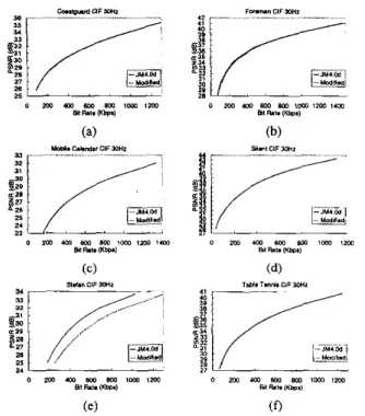
Figure 5 : The rate distortion curves of various standard sequences generated by JM4.0d and our modified software.
Figure 6: (a) Number of intra MBs V.S. frame; (b) Number of bits
required V.S. frame.
Figure 7: Proposed architecture for integer ME.
and Hadamard transformopened. Six standard sequences are tested from low bit-rates to high bit-rates. Our modifications result in al- most no PSNR degradation except for Stefan. This is because the true motion vectors of Stefan from frame #I75 to #I95 and from frame #230 to a 8 0 are larger than the search range. Here, we can see the significant gain when the search range center of a MB is located at the MV predictor. Nevertheless, as we stated before, if we located the search range center at (0, O ) , take search range of 1-16, +I61 as an example, the memory transfer of the overlapped
2/3 search area from the external RAM lo on-chip SRAM can be saved for adjacent MBs. Therefore, in the view paint of hardware engineers,
we
suggestto
increase the search
range to [-24,
t241
or
larger if the extra cost of on-chip SRAM is affordable. Note that
in this case, the saving of system bus bandwidth is 75% because there are 314 overlapped search area for two adjacent MBs. If the
design target is low cost, we suggest to solve this problem at the algorithmic level. That is, we can adjust the search range center by the number of intra MBs in the previous frame. If the t ~ e MVs
are beyond the search range, many MBs will bc intra-coded. We can observe this situation in Fig. 6. If the number of intra MBs in previous frame is smaller than a threshold, we can use (0.0) as search range center and reuse the overlapped search area. Other- wise, we can reload the whole search area that are centered at the M V predictor if the real-time requirements still can be achieved.
4.
HARDWARE
ARCHITECTUREI n this section, we will describe our architecture for the integer ME module, which is the most computationally intensive part in the en- coder. Full search scheme is adopted because of its simplicity and regularity. The SADs of the 41 blocks in a search position are com-
puted in parallel in one clock cycle. Our architecture is illustrated in Fig. 7. Each circle stands for a processing element (PE). Each 8-bit pixel in the current MB is stored in the corresponding PE.
In each cycle, 16x1 8-bit search area pixels are inputted, and each
pixel is broadcasted to 1x16 PES. Every PE computes the absolute difference between the current MB pixel and the search area pixel. Each rectangle that contains 4x1 PES is responsible for calculating the sum of 4x1 absolute differences. The 4x1 sum is then passed to the right. The rectangle shaded with slash lines adds the 4x1 sum from its left side and the result from top. The added result is latched in the register. The rest small rectangles are registers and are used as delay lines. In this way. the sixteen 4x4 SADs can be
computed in one cycle. The eight 8x4 SADs, eight 4x8 SADs, four
8x8 SADs, two 16x8 SADs, two 8x16 SADs, and one 16x16 SAD
can also
beeasily
computedin
thesame cycle by an adder
tree.An example of the detailed data flow is shown in Fig. 8. As-
sume the search range is [-16, +16], the search area is 48x48, and each square stands for 16x16 search area. After the current
MB
are loaded into each PE, 16x1 search area pixels are inputted in each cycle. At cycle 0, the left 16x1 pixels on the row 0 in the search area are inputted. Then, the left 16x1 pixels on row 1 are inputted at cycle I , and go on. At cycle 15, all the candidate block data of search position (-16, -16) have been broadcasted to the PE array, and the SADs of 41 blocks at search position (-16, -16) are calculated in parallel. The SADs of search position (-16, -15)
-
(-16, +16) will be available at cycle16
to 47, respectively. The rest search positions can be traced by analogy. In order to output the 16x1 pixels in parallel. we have to store the search area data in different 16 on-chip SRAM modules.As you can see, the utilization of the previous data Row cannot achieve 100%. When the search position is changed in the hod- zontal direction, extra 15 cycles are required to load the candidate block data. The advanced data Row is shown in Fig. 9. Now the P E array needs two ports of 16x1 search area data. The top 48x32 search area data are stored in 16 on-chip SRAM modules, and the bottom 48x16 search area are stored in another 16 on-chip SRAM modules so that 32 search area pixels can be outputted in one cycle.
Cycle 0 Cycle 15 Cycle 16 - 47 Cycle 48 - 96 Cycle 1535. 1583
Figure 8: Basic data flow.
Cycle 0
.
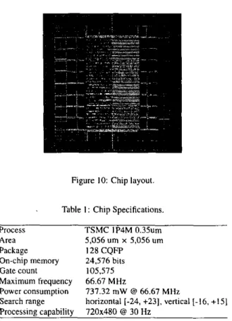
32 Cycle 33 Cycle 34 - 47 Cycle 48-65 Cycle 66-80Figure IO: Chip layout. Figure 9: Advanced data flow.
At cycle 0 to 32, the new data flow is the same as the previous one. At cycle 33. not only the original 16x1 pixels in Fig. 8 but also the additional 16x1 pixels (at cycle 48 of the previous flow) are in- putted to the PE array. At this time, the 16x1 PES on row 0 (the top
16x1 PES in Fig. 7) should choose the new additional 16x1 pixels while the rest 16x15 PES on row 1-15 should choose the original
16x1 data. At cycle 34 to 47, the SADs of search positions (-16.
+2) - (-16, +16) are computed, and in the mean time, the search area data required for search position (-15, -16) are also inputted to the PE array. During cycle 33-47, the 16x1 PES on each row should select the proper 16x1 search area data in order to gel the correct results. In this way, when the search position is changed in the horizontal position. no bubble cycles exist so that the through- put can be increased. When ping-pong mode current MB buffers
are implemented. the utilization is 100%. and the required cycles for each M B is 1089. In sum, our architecture is a 2-D systolic array with I-D data broadcasting and I-D partial result reuse (4x1 SADs). Sixteen 4x4 SADs are generated by the PE array, and a parallel adder tree computes the rest SADs of larger block sizes.
S. IMPLEMENTATION
Our design goal is listed as follows: 720x480 frame size, 30 frames per second, search range [-24, +231 in the horizontal direction and (-16, +I51 in the vertical direction. Our design is described by Vcrilog HDL and synthesized by SYNOPSYS Design Analyzer with AVANT! 0.35um lP4M cell library. The backend tool we used is CADENCE Silicon Ensemble,
Figure 10 shows our chip layout. We did not use ping-pong mode current ME buffers in order to save chip area. Therefore, some extra cycles are needed to load the current MB data. The utilization of the PE array is 97% and the required frequency is 64.1 IMHz. The critical path constraint is set to 15ns. We use sixteen 128x8 SRAMs to store the upper 64x32 search area data and another sixteen 64x8 SRAMs to store the bottom 64x16 search area dam The chip specifications are shown in Table 1. The total gate count is about 106K. The PE array requires 64K gates, the current MB buffer requires 15K gates, and the rest gates are spent on the 41 comparators to find the minimum SADs, registers to hold the minimum SADs and corresponding MVs, and control circuits.
Table I : Chip Specifications.
Process TSMC IP4M 0.35um
Area 5,056 um x 5,056 um
Package 128 CQFT
On-chip memory 24.576 bits
Fate count 105,575 Maximum frequency 66.67 MHz Power consumption Search range Processing capability 737.32 mW @ 66.67 MHz
horizontal [-24, +23]. vertical [-16. +IS]
720x480 @ 30 Hz
6. CONCLUSION
We proposed a hardware architecture of variable block size motion estimation dedicated for H.264. The architecture design begins with the analysis of the reference software. We removed the data dependencies that prevents parallel processing and MB pipelining. The architecture contains a PE array, which is a 2-D systolic ar- ray with I - D data broadcasting and I - D partial result reuse, and a parallel adder tree to generate the SAD of larger block sizes based on 4x4 SADs. Our memory access scheme can result in 100% uti-
lization of PE array. Real-time applications of 720x480 frame at
30Hz can be achieved only under 64.1 IMHz.
7.
FUTURE WORK
We are now establishing the cell-based design flow of 0.25um technology. We plan to integrate the current design together with quarter-pixel ME and intra prediction using 0.25 um technology.
8. REFERENCES
[ I ]
H.264 and ISONEC 14496-10 AVC), July, 2002. 121 Joint Wdeo Team ( J V T ) sofrware JM4.0d. August, 2002.
131 T.C. Wang, Y.W. Huang, H.C. Fang, andL.G. Chen, "Perfor- mance analysis of hardware oriented algorithm modifications in H.264." submitted to lEEE lnrernarional Conference on
Acoustics, Speech, and Signal Processing, 2003.
Committee Drafi of Joint Wdeo SpeciJicotion (/TU-T Xec.