Intermetallic Reactions in Sn-3.5Ag Solder Ball Grid Array
Packages with Ag/Cu and Au/Ni/Cu Pads
CHIH-CHIEN CHI1and TUNG-HAN CHUANG1,2
1.—Institute of Materials Science and Engineering, National Taiwan University, Taipei 106, Taiwan. 2.—E-mail: tunghan@ntu.edu.tw
During the reflow process of Sn-3.5Ag solder ball grid array (BGA) packages with Ag/Cu and Au/Ni/Cu pads, Ag and Au thin films dissolve rapidly into the liquid solder, and the Cu and Ni layers react with the Sn-3.5Ag solder to form Cu6Sn5 and Ni3Sn4intermetallic compounds at the solder/pad interfaces, re-spectively. The Cu6Sn5intermetallic compounds also appear as clusters in the solder matrix of Ag surface-finished packages accompanied by Ag3Sn disper-sions. In the solder matrix of Au/Ni surface-finished specimens, Ag3Sn and AuSn4intermetallics can be observed, and their coarsening coincides progres-sively with the aging process. The interfacial Cu6Sn5and Ni3Sn4intermetallic layers grow by a diffusion-controlled mechanism after aging at 100 and 150°C. Ball shear strengths of the reflowed Sn-3.5Ag packages with both surface finishes are similar, displaying the same degradation tendencies as a result of the aging effect.
Key words: Sn-3.5Ag BGA, Ag and Au/Ni surface finishes, intermetallic compounds, reflow, aging
INTRODUCTION
Restriction of the use of Pb in solder alloys has become one of the most important issues for the electronics industry. Among a number of promising Pb-free solders, eutectic Sn-3.5Ag possesses the merits of high strength, improved creep resistance, longer fatigue life, low cost, and good wettability.1 On the other hand, Au/Ni metallization has been widely employed as a surface finish for printed cir-cuit boards (PCB) in electronic packages. The Au thin film provides the beneficial effects of oxidation protection and wetting improvement for Cu pads, while the Ni layer acts as a diffusion barrier between Au and Cu. However, the Au surface finish often causes the formation of AuSn4 intermetallic compounds as well as the embrittlement of solder joints, let alone the costly expense it entails.2 An alternative method for PCB surface finishing is the use of immersion Ag. The process takes just about 7 min., and the cost is nearly the same as those traditional surface finishes involving Sn.3 In addition to the cost advantage, immersion Ag pro-vides smooth surfaces and good wettability for liq-uid solder on Cu pads.
During the reflow of packages with Au/Ni/Cu or Ag/Cu pads, the Au or Ag surface finish dissolves rapidly into the solder matrix and a liquid/solid reaction occurs at the interface of the solder alloy with the Ni or Cu layer, respectively. The resultant intermetallic formation affects the bonding quality and material properties of the solder joints.4 In addition, the heat generated from the operation of electronic devices can cause further growth of inter-facial intermetallic compounds, which is critical to the reliability of the packages. Because Au/Ni sur-face finishing has been widely used in ball grid array (BGA) packages, its interfacial reactions with vari-ous Pb-free solders are often reported. However, information about soldering reactions on immersion Ag-metallized Cu pads is scant. In fact, the interme-tallic reactions between Sn-3.5Ag solder and Cu sub-strates have been investigated extensively in the literature, and they lead to the formation of a scal-lop-shaped Cu6Sn5intermetallic phase at the inter-face. As noted by these reports, the solid/solid reactions of Sn-3.5Ag/Cu couples are diffusion con-trolled,5–7while opinions would vary on the interme-tallic growth kinetics for liquid Sn-3.5Ag solders reacted with Cu substrates.8,9The effort of this pres-ent study is mainly concerned with the intermetallic compounds that form during the reflow and aging of Sn-3.5Ag solder BGA packages with an immersion (Received February 22, 2005; accepted November 9, 2005)
Ag surface finish. In this case, liquid/solid and solid/ solid reactions occur at the Sn-3.5Ag/Cu interfaces for the reflowed and aged specimens, respectively. For comparison, the investigation on the intermetallic reactions of Sn-3.5Ag packages with traditional Au/Ni surface finishes has also been included. Because the Au film dissolves rapidly at the onset of the reflow process, it is between the Sn-3.5Ag solder and Ni layer that the interfacial reactions take place.
EXPERIMENTAL PROCEDURES The Sn-3.5Ag BGA packages with Ag/Cu and Au/ Ni/Cu pads in this study contained 49 Cu pads with a thickness of 35 mm on each FR-4 substrate. For the Ag surface-finishing process, the Cu pads were immersion-coated with 0.2-mm-thick Ag film. On the other hand, the Au/Ni surface-finished Cu pads were electroplated with 5-mm-thick Ni and immer-sion plated with 0.5-mm-thick Au. Sn-3.5Ag (wt.%) solder balls of 0.4 mm in diameter were dipped in rosin mildly activated (RMA) flux, placed on the Ag/Cu and Au/Ni/Cu pads, and then reflowed in a hot-air furnace. The reflow furnace was equipped with five heating zones, and Fig. 1 provides the tem-perature profile for the soldering process of all Sn-3.5Ag packages in this study. After reflow, certain
specimens were further aged at 100 and 150°C for various times ranging from 100 to 1000 hr. The reflowed and aged Sn-3.5Ag BGA packages were cross-sectioned through a row of solder balls. For metallographic preparation, these specimens were ground with 2000-grit SiC paper and polished with 0.3-mm Al2O3 powder. The morphology of interme-tallic compounds in the solder matrix and at the solder/pad interface was then observed via scanning electron microscopy (SEM). The chemical composi-tions of various intermetallic phases were analyzed using an energy dispersive x-ray spectrometer (EDX) installed in the SEM.
The bonding strengths of the solder joints in Sn-3.5Ag BGA packages after reflow and aging were measured using ball shear tests, for which the shear rate and shear height were set at 0.1 mm/sec and 80 mm, respectively. Following the strength meas-urements, the fractography of these ball-sheared solder joints was observed in the SEM for charac-terization of the mechanical failure modes. In order to clarify the relationship between bonding strength at solder joints and mechanical properties of solder balls, the microhardnesses of the solder matrix in the reflowed and aged specimens were measured. For this purpose, the Vickers hardness test with an indentation size of 30mm and a load of 10 gf was used.
RESULTS AND DISCUSSION
Figure 2a shows the microstructure of a solder joint in the Sn-3.5Ag BGA package with the Ag/Cu pad after reflow. A great number of scallop-shaped Cu6Sn5intermetallic compounds appear at the interface between Sn-3.5Ag solder and Cu pad, which implies that the Ag surface-finished film on the Cu pad had been dissolving into the solder matrix during the reflow process. In this case, the Ag content in the solder ball increased from 3.50 wt.% to about 3.57 wt.%, which caused very fine Ag3Sn particles to pre-cipitate in the solidified solder matrix. In addition, many cluster-shaped Cu6Sn5 intermetallics were observed in the solder ball. Because these Cu6Sn5 intermetallic clusters in the solder matrix are much larger than the scallop-shaped intermetallic layers Fig. 1. Temperature profile for reflowing the Sn-3.5Ag BGA
pack-ages in this study.
Fig. 2. Morphology of intermetallic compounds at the (a) Ag/Cu and (b) Au/Ni/Cu solder/pad interface of a reflowed Sn-3.5Ag solder ball. Chi and Chuang 472
at the solder/pad interfaces, they should have been separately precipitated from within the solder matrix already supersaturated with dissolved Cu atoms prior to the formation of those interfacial Cu6Sn5 intermetallics. This phenomenon is differ-ent from what has been observed in the study of Chuang et al.8on the interfacial reactions between liquid Sn-3.5Ag and Cu substrates at a much higher temperature (.350°C) and for a longer melting time (.30 min.) as compared to the reflow conditions for this present study (see Fig. 1). In that case, some of the scallop-shaped Cu6Sn5intermetallic compounds were detached from the interface and floated into the solder matrix.
The microstructure of the reflowed Sn-3.5Ag sol-der joints with Au/Ni/Cu pads as shown in Fig. 2b also contains Ag3Sn phase in the solder matrix, which has been precipitated from the supersaturated Ag element in the Sn-3.5Ag alloy. However, the Ag3Sn precipitates in the packages with Au/Ni/Cu pads are much coarser than those in the Ag surface-finished packages and have a needle-shape appear-ance. In addition, the Au film on the Ni/Cu pads has dissolved into the solder matrix to form flake-shaped AuSn4 intermetallic compounds. At the solder/Ni interface, a continuous layer of scallop-shaped Ni3Sn4 intermetallic compounds can be observed.
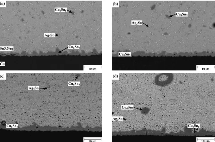
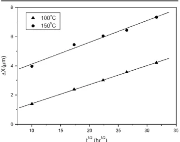
For the Sn-3.5Ag packages with Ag/Cu pads, the interfacial scallop-shaped Cu6Sn5 intermetallic compounds grow with increasing aging time during aging at 100°C, as shown in Fig. 3. Many Ag3Sn fine precipitates and Cu6Sn5 intermetallic clusters are distributed throughout the solder matrix. Figure 4 reveals that a certain amount of Ag3Sn coarse plates are formed at the front of interfacial Cu6Sn5 inter-metallic compounds when the aging temperature is raised to 150°C. Accompanied with further growth of these Cu6Sn5intermetallics, Cu3Sn intermetallic layers are formed between the interfacial Cu6Sn5 intermetallics and Cu pads. Furthermore, many voids can be observed in the interior of thee-Cu3Sn intermetallic phases. Priza and Wever reported that the diffusion coefficient of Cu ine-Cu3Sn intermetal-lics is greater than that of Sn.10It is the unbalanced interdiffusion that causes the formation of Kirken-dall voids in thee-Cu3Sn intermetallic layer. Figure 4 shows the appearance of a much greater number of cluster-shaped Cu6Sn5 intermetallic compounds in the solder matrix after aging at 150°C. The growth thicknesses of Cu6Sn5 and Cu3Sn interme-tallic compounds formed at the solder/pad interfaces were measured and are plotted in Fig. 5 vs. the square root of aging time. The curves follow a linear relation, which implies that the growth kinetics of both types of intermetallics is diffusion controlled. Fig. 3. Morphology of intermetallic compounds formed in the Sn-3.5Ag BGA packages with Ag/Cu pads after aging at 100°C for various time periods: (a) 300 hr, (b) 500 hr, (c) 700 hr, and (d) 1000 hr.
Accompanied by the formation of Cu6Sn5and Cu3Sn intermetallics, Cu pads also dissolved in a parabolic relation with the reaction time (Fig. 6).
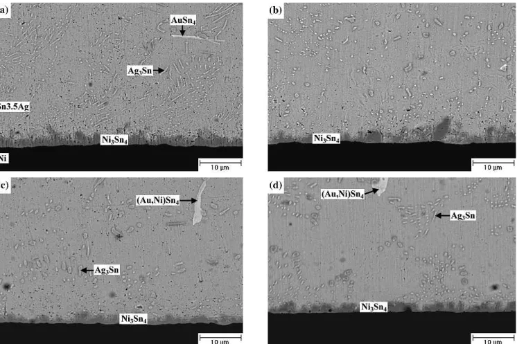
For the Sn-3.5Ag packages with Au/Ni/Cu pads, Fig. 7 reveals that aging at 100°C over 500 hr causes the needle-shaped Ag3Sn to break into particles, which will coarsen with increasing aging time. The
flake-shaped AuSn4intermetallics continue to remain in the solder matrix during the aging process, which is contrary to the phenomenon observed with tradi-tional Sn-37Pb BGA packages.11 In that case, the AuSn4intermetallic flakes are formed in the solder matrix of an as-reflowed Sn-37Pb package with the Au/Ni surface finish. However, those AuSn4
Fig. 4. Morphology of intermetallic compounds formed in the Sn-3.5Ag BGA packages with Ag/Cu pads after aging at 150°C for various time periods: (a) 300 hr, (b) 500 hr, (c) 700 hr, and (d) 1000 hr.
Fig. 5. Growth thickness (X) ofh-Cu6Sn5 ande-Cu3Sn interfacial intermetallics in Sn-3.5Ag BGA packages with Ag/Cu pads relative to the square root of aging time (t1/2).
Fig. 6. Dissolution thickness (DX) of Cu pads accompanying the formation of Cu6Sn5and Cu3Sn intermetallics relative to the square root of reaction time (t1/2).
Chi and Chuang 474
intermetallic compounds will migrate from the Sn-37Pb solder matrix to the Ni/Cu pads during the aging process. In Fig. 7, the AuSn4intermetallic flakes are also found to become thicker as the aging time increases to.700 hr. In addition, EDX analy-sis indicates that a certain amount of the Ni element has dissolved into the coarsened AuSn4 interme-tallic compounds, changing their composition to (Au0.66Ni0.34)Sn4. When the aging temperature is increased to 150°C, the needle-shaped Ag3Sn inter-metallics are broken into particles (see Fig. 8) at a lower aging time of about 300 hr as compared to the former case of aging at 100°C. Both the Ag3Sn par-ticles and (Au0.66Ni0.34)Sn4intermetallic flakes coarsen with increasing aging time. However, the Ag3Sn coarse plates in Fig. 4 have made no appearance in this case. Figure 8 gives evidences that the flake-shaped (Au0.66Ni0.34)Sn4 intermetallic compounds still remain in the Sn-3.5Ag solder matrix. As noted in Figs. 7 and 8, the (Au0.66Ni0.34)Sn4intermetallic flakes tend to couple with Ag3Sn particles. There-fore, the fact that the (Au0.66Ni0.34)Sn4intermetallic flakes have remained in the solder matrix can be attributed to the pinning effect of these Ag3Sn par-ticles. In addition, for the Sn-37Pb BGA packages with Au/Ni/Cu pads, it has been explained that the Ni layer attracts the AuSn4 intermetallics, causing them to migrate from the solder matrix to the Ni/Cu
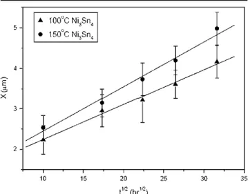
pad.12 In this present study, the (Au0.66Ni0.34)Sn4 intermetallic flakes that appear in the solder matrix contain the element Ni, which ought to throw more light on the stabilization of these intermetallics in the solder matrix (counter to their migration to the Ni/Cu pad). During aging at 100 and 150°C for Sn-3.5Ag packages with Au/Ni/Cu pads, the interfa-cial Ni3Sn4intermetallic compounds grow very slowly. Figure 9 indicates that the growth rate is also char-acterized by a parabolic relation and the reactions are diffusion controlled. The decrease in thickness of the decrease of Ni layer on the Cu pads caused by the Ni3Sn4intermetallic growth was quite minor.
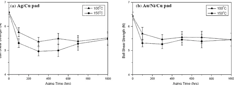
The solder joints in the reflowed Sn-3.5Ag BGA package with Ag/Cu pads possess a ball shear strength of 6.58 N. After aging at 100 and 150°C for 100 hr, Table I shows that the ball shear strengths have decreased to 5.75 and 5.30 N, respec-tively. With further increase of the aging time, the bonding strengths have remained almost constant, as shown by Fig. 10. Fractography of all reflowed and aged Sn-3.5Ag packages after ball shear tests reveals that the solder joints have fractured across the solder balls with ductile characteristics (Fig. 11). In order to elucidate the bonding strength degrada-tion of the solder joints after aging treatment, the microhardness of the solder balls in the reflowed and aged Sn-3.5Ag BGA specimens was measured, Fig. 7. Morphology of intermatallic compounds formed in the Sn-3.5Ag BGA packages with Au/Ni/Cu pads after aging at 100°C for various time periods: (a) 300 hr, (b) 500 hr, (c) 700 hr, and (d) 1000 hr.
as shown in Fig. 12a. The results indicate a consis-tency in the tendencies of ball shear strengths and solder microhardness relative to the aging time. It is obvious that the bonding strength degradation in Sn-3.5Ag packages is attributed to the softening of the solder matrix due to the aging treatments. The softening effect of the solder matrix after aging
may be correlated with the coarsening of Ag3Sn precipitates.
The ball shear strengths of Sn-3.5Ag packages with Au/Ni/Cu pads after reflow and aging are quite similar to the strengths of those with Ag/Cu pads (Table I and Fig. 10). For the reflowed specimens, a bonding strength of 6.45 N is obtained. After aging at 100 and 150°C for 100 hr, the ball shear strengths have decreased to 5.71 and 5.31 N, respectively, which will also remain nearly constant as the aging time is increased further. Figure 13 reveals that the Au/Ni surface-finished Sn-3.5Ag solder joints, after ball shear tests have fractured across the solder balls with ductile characteristics. The decreasing
Fig. 9. Growth thickness (X) of Ni3Sn4interfacial intermetallics in Sn-3.5Ag BGA packages with Au/Ni/Cu pads relative to the square root of aging time (t1/2).
Fig. 8. Morphology of intermetallic compounds formed in the Sn-3.5Ag BGA packages with Au/Ni/Cu pads after aging at 150°C for various time periods: (a) 300 hr, (b) 500 hr, (c) 700 hr, and (d) 1000 hr.
Table I. Ball Shear Strengths in N of Sn-3.5 Ag Solder BGA Packages with Ag/Cu Pads after Aging at 100 and 150°C for Various Time Periods Aging Time (hr)
Ag/Cu Pad Au/Ni/Cu Pad
100°C 150°C 100°C 150°C 0 (as reflowed) 6.58 6.58 6.45 6.45 100 5.75 5.30 5.71 5.31 300 5.36 4.96 5.47 5.26 500 5.49 5.00 5.56 5.45 700 5.38 5.28 5.55 5.39 1000 5.52 5.47 5.46 5.45
Chi and Chuang 476
tendency of microhardness measurements for the Sn-3.5Ag solder balls (Fig. 12b) can also reflect on the degradation of bonding strengths due to the aging treatment. The coarsening of Ag3Sn precipi-tates and AuSn4intermetallic flakes is responsible for the softening effect of the solder matrix similar to the case of the Ag surface-finished packages. Comparing the fractrography of Sn-3.5Ag solder joints with Ag/Cu pads (Fig. 11) and Au/Ni/Cu pads (Fig. 13), it can be observed that the former contain
many dimples, while the latter are free from voids. Such a discrepancy should be attributed to the large Cu6Sn5 intermetallic clusters distributed in the solder matrix of immersion Ag surface-finished packages.
CONCLUSIONS
It was the purpose of this study to investigate the intermetallic reactions in Sn-3.5Ag BGA packages with Cu pads using Ag and Au/Ni surface finishes. Fig. 10. Ball strengths of the Sn-3.5Ag solder BGA packages with (a) Ag/Cu and (b) Au/Ni/Cu pads after aging at 100 and 150°C for various time periods.
Fig. 11. Fractography of Sn-3.5Ag solder joints in BGA packages with the immersion Ag surface finish after ball shear tests: (a) as reflowed; (b) 100°C, 1000-hr aging; and (c) 150°C, 1000-hr aging.
Fig. 12. Microhardness of solder matrix for Sn-3.5Ag BGA packages with (a) Ag/Cu and (b) Au/Ni/Cu pads after aging at 100 and 150°C for various time periods.
Experimental results indicate that the immersion Ag and Au thin films dissolve rapidly into the solder matrix during the reflow process. Interfacial reac-tions occur at the interfaces of the liquid Sn-3.5Ag solder/Cu layer and the Sn-3.5Ag solder/Ni layer, leading to the formation of Cu6Sn5 and Ni3Sn4 in-termetallic compounds, respectively. Further aging at 100 and 150°C causes these interfacial interme-tallics to grow via a diffusion-controlled mechanism. For the Ag surface-finished Sn-3.5Ag packages, an extra intermetallic layer of Cu3Sn accompanied by many Kirkendall voids appear between Cu6Sn5 intermetallics and Cu pads after prolonged aging at 150°C. For the reflowed Sn-3.5Ag packages with Ag/Cu and Au/Ni/Cu pads, Ag3Sn precipitates and flake-shaped AuSn4intermetallics appear in the sol-der matrices, respectively. Aging treatments result in the coarsening of Ag3Sn particles and AuSn4 flakes as well as a softening effect of the solder matrix, thereby decreasing the ball shear strengths from 6.58 and 6.45 N (in the reflowed state) to about 5.35 6 0.39 and 5.46 6 0.25 N for the Sn-3.5Ag packages with Ag/Cu and Au/Ni/Cu pads, respec-tively. Although the fracture surfaces of both surface-finished packages after ball shear tests revealed ductile characteristics, the large Cu6Sn5 intermetallic clusters in the Sn-3.5Ag solder joints with Ag/Cu pads resulted in many dimples on their
fractrographies, in contrast to those specimens with Au/Ni/Cu pads.
ACKNOWLEDGMENT
Sincere thanks go to National Science Council, Taiwan, for sponsoring this research under Grant No. NSC-93-2216-E002-024.
REFERENCES 1. J. Glazer, Int. Mater. Rev. 40, 65 (1995).
2. D.M. Jacobson and G. Humpston, Gold Bull. 22, 9 (1989). 3. J.H. Lau, C.P. Wong, N.C. Lee, and R.S.W. Lee, Electronics
Manufacturing: With Lead-Free, Halogen-Free Conductive-Adhesive Materials (New York: McGraw-Hill Handbooks, 2003).
4. P.G. Harris and K.S. Chaggar, Soldering Surf. Mount Tech-nol. 10, 38 (1998).
5. D.Q. Yu, C.M.L. Wu, C.M.T. Law, L. Wang, and J.K.L. Lai, J. Alloys Compd. 392, 192 (2005).
6. T.L. Su, L.C. Tsao, S.Y. Chang, and T.H. Chuang, J. Mater. Eng. Perform. 11, 481 (2002).
7. M. He, W.H. Lau, G. Qi, and Z. Chen, Thin Solid Films 462-463, 376 (2004).
8. T.H. Chuang, H.M. Wu, M.D. Cheng, S.Y. Chang, and S.F. Yen, J. Electron. Mater. 33, 22 (2004).
9. K.S. Bae and S.J. Kim, J. Electron. Mater. 30, 1452 (2001). 10. N. Prinz and H. Wever, Phys. Status Solidi A 61, 505 (1998). 11. A.M. Minor and J.W. Morris, Jr., J. Electron. Mater. 29, 1170
(2000).
12. C.E. Ho, Y.M. Chen, and C.R. Kao, J. Electron. Mater. 28, 1231 (1999).
Fig. 13. Fractrography of Sn-3.5Ag solder joints in BGA packages with Au/Ni surface finish after ball shear tests: (a) as reflowed (b) 100°C, 1000-hr aging; (c) 150°C, 1000-hr aging.
Chi and Chuang 478