A Rate Control Mechanism Based on Client Feedback for Transporting MPEG-4 Video over the Internet
10
0
0
全文
(2) they want to watch without waiting for the completion of downloading, and there is no need preparing storage device with enough capacity in the client. The current Internet is a best effort service network and interconnects sites with widely varying bandwidth capabilities. It is simple to reconnect and to retransmit the lost data when congestion or disconnection occurs during downloading a discrete file. However, it is not desirable when downloading continuous data. That is, display will be interrupted if reconnection or retransmission is to be proceeded. The most challenging issue is how to keep the data transmission continuous and to achieve the best perceptual quality when continuous media data is transmitted over the Internet. To avoid the influences of congestion, the server has to control the data output rate according to the perceived network status. Packet loss or disconnection may occur if the server dose not lower its output rate during the congestion. A video server may serve more than one client, and buffer has to be reserved in each connection to smooth the data output rate. Fig. 1 shows the concepts of Internet video streaming.. • Digital television • Interactive graphics applications (synthetic content) • Interactive multimedia (World Wide Web, distribution of and access to content) MPEG-4 provides the standardized technological elements enabling the integration of the production, distribution and content access paradigms of the above three fields [1]. The most important goal of both the MPEG-1 and MPEG-2 standards was to make the storage and transmission of digital audiovisual material more efficient through compression techniques. Because the video encoding of the MPEG-1 and MPEG-2 is frame-based, to interact with the frame-based video content is limited to the video frame level [2]. MPEG-4 includes the concepts of video object (VO) and video object plane (VOP). A video object in a scene is an entity that a user may access and manipulate. The instances of video objects at a given time are called video object planes (VOPs) [2]. Those VOPs can be separately encoded, stored, or transmitted. The MPEG-4 based multimedia systems can reassemble, delete, or replace some VOPs of the video stream as necessary for providing human-machine interaction. In Fig. 2, the scene consists of one background and two foreground objects, which can be encoded separately, and the receiver can decode any single object and manipulate it at presentation time. For example, one foreground object can be mixed with other background object to make a new scene.. Fig. 1 Concepts of Internet video streaming To minimize the influence of packet delay or disorder, buffer has to be reserved in the client, too. Besides, the client has to monitor network conditions to provide some information for the server. Although the server has controlled the data output rate to prevent packet loss, packet loss is unavoidable in the Internet and may have a significant impact on perceptual quality. The client has to deal with the incomplete data when packet loss occurs: for instance, to discard or to repair the incomplete video frames.. 2.2 Overview of the MPEG-4 Encoding MPEG-4 is an ISO/IEC standard developed by MPEG (Moving Picture Experts Group), the committee that also developed the standards MPEG-1 and MPEG-2. These standards made interactive video on CD-ROM and Digital Television possible [1]. MPEG-4 is built on the proven success of three fields:. Fig. 2 Content-based image coding [4] MPEG-4 video encoding supports all functionalities already in MPEG-1 and MPEG-2, in particular the compression efficiency. Fig. 3 shows a detailed block diagram of the MPEG-4 video encoder. This is a conventional hybrid DCT structure, but augmented by further blocks. There is a block for contour coding and a number of prediction modes are also supported: • conventional motion compensated and block-based (8×8 and 16×16 blocks) prediction • global motion compensation using affine motion parameters • static and dynamic sprite prediction for the.
(3) background. RTP provides some basic functionalities which are common to almost all real-time applications. A key feature supported by RTP is the packet sequence number, which can be used to detect packet loss and to reorder packets at the receiver. RTCP provides QoS feedback through the use of sender reports (SR) and receiver reports (RR) at the source and destination [5].. 2.4 An Architecture for Transporting MPEG-4 Video. Fig. 3 Block diagram of the MPEG-4 video encoder [3] The improved compression efficiency is mainly achieved by the following measures: • improved slice layer and macroblock layer syntax • switched 8×8 and 16×16 motion compression, which allows for more precise prediction • block-overlapping motion compensation, which reduces block artifacts at low data rates • global motion compensation for scenes with global camera motion • post-filtering avoid ringing and block artifacts Although increased compression efficiency is not the main target of the MPEG-4 standardization, MPEG-4 will offer efficient coding at bit rates between 5 kbit/s and 15 Mbit/s or higher, so that a significantly larger range than that of MPEG-1 and MPEG-2 will be covered. At low data rates between 5 kbit/s and 100 kbit/s the quality will be better than that of H.263, while at high data ranges, between 1 Mbit/s and 15 Mbit/s, a quality better than that of MPEG-2 is targeted [3].. Fig. 4 shows the end-to-end architecture for transporting MPEG-4 video over the Internet, and it includes stages as the following: • raw bit-stream is encoded by the MPEG-4 encoder • the compressed video bit-stream is packetized and then passed through the RTP/UDP/IP module before entering the Internet For packets that are successfully delivered to the client, the following are done by the client: • packets first pass through the RTP/UDP/IP module • the compressed bit-stream is decoded by the MPEG-4 decoder A QoS monitor is kept at the client side to detect network congestion status based on the behavior of the arriving packets [5]. The information of network congestion status is sent to the server by the feedback control protocol. Based on this information, the server estimates the available network bandwidth and change the output rate of the MPEG-4 video stream.. 2.3 RTP and RTCP Protocols (RFC 1889) Although TCP protocol gives reliability on transmission of data over the Internet, the delays of retransmission is not acceptable for MPEG-4 video applications. It is better to employ UDP protocol as the transport protocol for the transmission of MPEG-4 video data. Since UDP does not provide reliability that TCP does, a layer to detect packet loss need to be added [6]. RTP (real-time transport protocol) is an Internet standard protocol, which provides end-to-end delivery services for data with real-time characteristics, such as interactive audio and video. RTCP (RTP control protocol) monitors the quality of service and to convey information about the participants in an on-going session [6].. Fig. 4 An end-to-end architecture transporting MPEG-4 video [5]. for. Fig. 5 shows the protocol stack for transporting MPEG-4 video. The visual information is compressed at the compression layer, and generates elemenary streams (ESs), which contain the coded representation of the VOs. The ESs are packetized at the SL (synchronization layer), the SL-packetized streams include information about timing and synchronization, as well as fragmentation and random access [5]. Streams are multiplexed into a FlexMux stream at the TransMux Layer, which is then passed through the RTP, UDP, and IP.
(4) layers. The resulting packets are sent into the Internet. At the client side, the video stream is processed in the reverse way.. TCP manner, normally the output rate is reduced to 1/2. At first, we describe the source-based rate control based on additive increase and multiplicative decrease (AIMD) algorithm [5]. The AIMD rate control algorithm is shown as follows: if (p ≦ Pth) r := min{(r + AIR), MaxR} else r := max{(α × r), MinR} ,. Fig. 5 Data format in MPEG-4 in each processing layer at an end system [5]. where p is the packet loss ratio; Pth is the threshold for the packet loss ratio; r is the sending rate at the source; AIR is the additive increase rate; MaxR and MinR are the maximum rate and the minimum rate of the sender, respectively; and α is the multiplicative decrease factor. Packet loss ratio p is measured by the receiver and conveyed back to the sender. An example of source rate behavior under the AIMD rate control is illustrated in Fig. 6.. 2.5 Rate Control Internet video applications, which differ from other applications, typically have the limitations of packet delay and loss. The Internet today support best-effort service only, and there is no bandwidth-reservation mechanism or other QoS guarantees. Therefore, a mechanism must be in place for MPEG-4 transporting system to sense network conditions, so that the server can adjust the appropriate output rate [5]. Ideally, it is better to perform congestion indication and feedback by switches or routers of the Internet. Under such an environment, it is possible to design powerful feedback control mechanism that the server can calculate the accurate available bandwidth. But in the current Internet environment, switches or routers do not report information about network conditions. Under such an environment, we treat the Internet as a black box where packet loss and delay are beyond our control. The feedback control mechanism will solely be placed on the end points (server and client) without any additional requirements on IP switches or routers [5]. At the beginning, the server gradually increases data output rate and probe available network bandwidth. The data output rate will overshoot the available bandwidth and congestion may occur. The client monitors network condition all the time and sends information back to the server. Once the server receives the feedback, it continually increases or decreases its output rate. In order to match the. Fig. 6 Source rate behavior under the AIMD rate control [11] Another source-based rate control mechanism is the multiplicative increase and multiplicative decrease (MIMD) algorithm [12]. The MIMD rate control algorithm is shown as follows: if (med_loss > tol_loss) max_rate = max(max_rate / 2, min_rate); else max_rate = gain × max_rate; During a control action, the control algorithm adjusts the maximum output rate of the coder max_rate so that the median loss rate stays below a tolerable loss rate. The median loss rate is denoted by med_loss, and the tolerable loss rate by med_loss. Specially, max_rate is decreased by a factor of two if the median loss rate is larger than tol_loss. Otherwise, it is increased by a fixed fraction of its current value. An example of source rate behavior under the MIMD rate control is illustrated in Fig. 7, where.
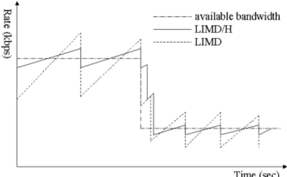
(5) we set gain = 1.02.. Fig. 7 Source rate behavior under the MIMD rate control The source rate behaviors under the AIMD and MIMD algorithms have a major disadvantage: it cannot decrease the increment of the server’s rate when the rate gets close to the link bandwidth. That is, wide oscillation and more packet losses will occur due to this characteristic. The third source-based rate control mechanism is the linear increase and multiplicative decrease with history (LIMD/H) algorithm [13]. The LIMD algorithm is the same with the AIMD algorithm. The LIMD/H rate control algorithm is shown as follows: if (f = 0) r ← r + α, and hi ← 1. else if (f > 0) r ← r × (1 – β × hi+1), and hi+1 ← 2hi. , where r denotes the sending rate, f the loss fraction, α the linear increase constant, β the multiplicative decrease constant, h the history parameter, and i the time step. The h variable, initially set to 1, is doubled if there is a packet loss in a time step, and reset to 1 if there is no packet loss. In case of LIMD/H, β is set to be a small value (between 0.1 and 0.2) in order to achieve smooth variations of server’s rate when the available bandwidth is invariant. LIMD/H thus throttles its transmission rate gently when there was no packet loss in the previous time step, and progressively more aggressively when previous time step has also experienced packet loss. An example of source rate behavior under the LIMD/H rate control is illustrated in Fig. 8. In order to design the algorithm to be TCP-friendly, α needs to be adjusted by the following rule: α = 3β The rule is proved in 2−β [13], and yields [α, β] pairs of [0.15, 0.1], [0.33, 0.2], [0.53, 0.3], [1, 0.5], etc.. Fig. 8 Source rate behavior under the LIMD/H rate control [13] Although the LIMD/H achieves smooth variations of server’s rate when the available bandwidth is invariant, it cannot increase the server’s rate adaptively when the rate is far below the link bandwidth. In order to employ a rate control mechanism that can increase the rate adaptively when the unused bandwidth is large, and can smooth the variations of rate when the rate getting close to the link bandwidth, we present a rate control mechanism based on client feedback applied on transmission of MPEG-4 video. The detailed mechanism will be described in Chapter 3.. 3. SYSTEM ARCHITECTURE 3.1 Overview In order to proceed out experiments on rate control mechanism based on client feedback, we have to build an end-to-end MPEG-4 delivery system that transports encoded MPEG-4 video data over the Internet. The system mainly consists of two parts: server and client, and follows the architecture described in Section 2.4. The system architecture will be described in Section 3.1.1 and 3.1.2. 3.1.1 Server Fig. 9 shows the block diagram of the server. The YUV raw video data is input into the MPEG-4 encoder, MPEG-4 compressed data is generated, and then the compressed data is stored in the storage devices. We use Microsoft Optimization Model Software 3.0-010315 to be our MPEG-4 encoder, which is the reference software of the MPEG-4 standardization process [8]. In the output rate control module, some video frames are discarded according to the value of output rate limit, and the remaining frames are packetized into several packets. Finally, data packets pass through the network module and to be sent into the Internet..
(6) Fig. 9 System architecture of the server in video streaming. Fig. 10 Output rate control module in video streaming. Fig. 11 Network module of the server Fig. 10 shows the block diagram of the output rate control module. Frame discarding module periodically keeps the value of remaining output size available in a time interval and determines whether the next coming frame is to be discarded. If the total available output size in a time interval is not enough for all of the frames, some frames have to be discarded. The order of frame discarding is according to the importance of I-frame, P-frame, and B-frame. The remaining frames are input into buffer and are sent to the client. Fig. 11 shows the network module of the server. The output rate control module generates a packetized stream, which is turned into RTP packets. On the other hand, the information from feedback control module is transferred to the RTCP generator. The resulting RTCP and RTP packets go to the UDP/IP layer for transport over the Internet.. 3.1.2 Client Fig. 12 shows the block diagram of a client. It is similar to the one described in Section 2.4. When the client receives a packet, the packet is passed through the network module, and the compressed MPEG-4 video data is input into the buffer of the MPEG-4 decoder. Finally, data is decoded and is displayed by the display device. Simultaneously, the QoS monitor keeps track of the congestion status of the network according to the received packets. Information about previous network condition is sent to the server by the feedback control module.. Fig. 12 System architecture of the client Fig. 13 shows the network module of the client. The received IP packets are first unpacked by UDP/IP layer, and are dispatched by filter to RTP and RTCP analyzers. RTP packets are unpacked by RTP analyzer and put into the buffer of MPEG-4 decoder. At the same time, QoS monitor detects and records the packet loss and data-bits received for information used to be feedback to the server. On the other hand, the RTCP analyzer unpacks RTCP packets and sends the information to the feedback control module.. Fig. 13 Network module of the client. 3.2 Packetization In order to achieve the optimal transport of MPEG-4 video over the Internet, an appropriate.
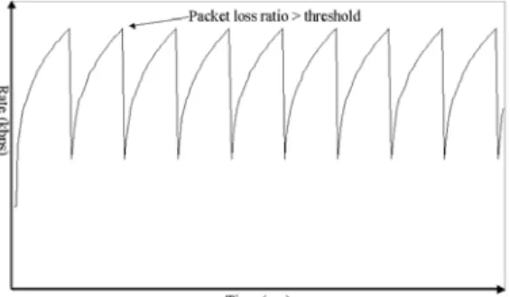
(7) packetization algorithm has to be employed. It is clear that the use of large packet size will reduce the total number of generated packets and overhead. On the other hand, the packet size cannot be larger than the path MTU (maximum transmission unit). Path MTU is defined to be the minimum of the MTUs along all the traversing links from the source to the destination. This is because any packet larger than path MTU will result in IP fragmentation, which brings overhead for each fragmented packet. To make things worse, loss of one fragmented packet will corrupt other fragmented packets within the original packet. Furthermore, for MPEG-4 video, it is also not advisable to packetize the data that contain information across two VOPs. With these considerations, the packet size is chosen to be the minimum of the current VOP size and the path MTU [14]. The packetization algorithm we use in this experiment is shown as follows: while (there is encoded data to be packetized) { search for next VOP_start_code and BitCount counts the number of bits; if ((next VOP_start_code is found) and (BitCount – length of VOP_start_code ≦ MaxPL)) { /* Packetize by VOP boundary */ packetize the bits before next VOP_start_code; } else if (BitCount – length of VOP_start_code > MaxPL) { Packetize as many bits as possible without exceeding MaxPL and without crossing into next VOP; } else { /* Next VOP_start_code is not found */ Packetize the remaining data; } } BitCount is a counter that registers the number of bits read for current packetization process. MaxPL is the maximum payload length and is equals to (path MTU – length of headers). VOP_start_code is a predefined code at the beginning of a VOP and is regarded as the boundary between two consecutive VOPs. If a complete VOP fits into a packet, then packetize such VOP with a single packet. Otherwise, as many bits as possible will be packetized into a packet without crossing over into the next VOP even if space is available in the last packet for the current VOP, i.e. data from consecutive VOPs are never put into the same packet. This packetization algorithm achieves. robustness to packet loss [14].. 3.3 Rate Control Mechanism In every time interval, the client keeps track of the estimated transmit rate. Sˆk and then. compares it with the client’s measurement of the actual receiving rate Ok to dictate the future transmission rate Sˆ k +1 . Sˆ k +1 is sent to the server as the data output rate in the next time interval [9]. If there is no congestion in the network, the server gradually increases the transmission rate until the packet loss ratio exceeds the threshold. When congestion occurs, the client goes into the congestion mode and sends feedback to the server to decrease the transmission rate. The mechanism is described as follows: Sˆk +1 = Sˆk + µε ( k ) ε (k ) = α × (. Ok β ) Sˆ. if packet loss is under the. k. threshold ε ( k ) = −γ × Sˆk threshold ,. if packet loss exceeds the. where k denotes a time step index, µ is the adaptation factor and ε(k) is the error determined based on the transmission rate, the receiving rate and packet loss. In case the packet loss is under the threshold, α and β determine the increasing rate. When β is larger, the server recovers the transmission rate faster after decreasing the transmission rate due to congestion. Additionally, the proposed mechanism minimizes the number of packet loss because it smoothly decreases the increment of transmission rate to near the link bandwidth. An example of source rate behavior is illustrated in Fig. 14.. Fig. 14 Source rate behavior under the proposed rate control mechanism In case the packet loss exceeds the threshold, γ determines the decrement of server’s output rate. We use γ = 0.5 because it is matched with TCP mechanism. It decreases the transmission rate at.
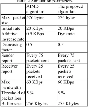
(8) one half as soon as it detects congestion so that it behaves TCP friendly manner. That is, it shares the available bandwidth fairly with TCP mechanism. All three factors are related to each other, especially α and γ are strongly related to determine the TCP friendly manner.. 4. EXPERIMENTS AND RESULTS 4.1 Simulation Environment 4.1.1 Data Source The source data we use is the standard raw video sequence “Bream” in CIF format for the MPEG-4 video encoder. The encoder performs MPEG-4 coding described in Section 2.2. The encoded bit-stream is packetized with the packetization algorithm described in Section 3.2 as well as RTP/UDP/IP protocol before being sent to the network. Packets may be dropped due to congestion in the network. For arriving packets, the client extracts the packet content to form the bit-stream for the MPEG-4 decoder. For a lost packet, the VOP associated with the lost packet will be discarded and a previous VOP will be copied over. The source encoder encodes an Intra-VOP every 15 frames. The source data is divided into two video objects, and these two objects are encoded into two MPEG-4 bit-streams. VO1 is a foreground object which is a bream swimming, and VO2 is a background object that pans from right to left slowly. Table 1 shows the Information of source data. Table 1 Information of source data VO1 VO2. Resolution 352×288 pixels Frame rate 30 frames/s I-VOP Every 15 frames P-VOP 4 between 2 I-frames B-VOP 2 between 2 P-frames Size of Max: 6511 bytes I-frame Min: 2482 bytes Avg.: 5633 bytes Size of Max: 3082 bytes P-frame Min: 1169 bytes Avg.: 1698 bytes Size of Max: 2575 bytes B-frame Min: 791 bytes Avg.: 1290 bytes. 352×288 pixels 30 frames/s Every 15 frames 4 between 2 I-frames 2 between 2 P-frames Max: 2527 bytes Min: 1963 bytes Avg.: 2213 bytes Max: 447 bytes Min: 265 bytes Avg.: 337 bytes Max: 1149 bytes Min: 315 bytes Avg.: 530 bytes. 4.1.2 Network Topology We employ the standard peer-to-peer benchmark network configuration as shown in Fig. 15. Such a simple network configuration captures the fundamental property of a transport path within the Internet cloud since there is only one bottleneck link between the server and the client. In the configuration of routers, buffer size is 10 Kbytes and buffer management is tail dropping. In this experiment, we set the maximum available bandwidth of the bottleneck link (link 12) to 60 Kbytes/s.. Fig. 15 A peer-to-peer network In this experiment we employ the AIMD algorithm described in Section 2.5 as the comparison. Table 2 shows the simulation parameters of the two algorithms. Ideally, the packet size is defined to be the minimum of the MTUs (maximum transit unit) along all the traversing links from the source to the destination. In the case when path MTU information is not available, the default MTU, i.e., 576 bytes, will be used [5]. Table 2 Simulation parameters AIMD The proposed algorithm algorithm Max packet 576 bytes 576 bytes size Initial rate 20 KBps 20 KBps Additive 0.5 KBps Dynamic increase rate Decreasing 0.5 0.5 factor Sender Every 75 Every 75 report packets sent packets sent Receiver Every 25 Every 25 report packets packets received received Max 60 KBps 60 KBps bandwidth Threshold of 5 % 5% packet loss Buffer size 256 Kbytes 256 Kbytes 4.1.3 Frame Discarding During the transmission of MPEG-4 bit-stream over the Internet, if the total available output size in a time interval is not enough to accommodate all of the frames, some frames have to be discarded. The order of frame discarding is listed as follows: • B-frame of VO2 • P-frame of VO2.
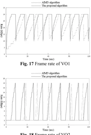
(9) • B-frame of VO1 • P-frame of VO1 In this experiment we do not discard I-frames of VO1 and VO2 to ensure the minimum limit of display quality.. 4.2 Experimental Results 4.2.1 Data Output Rate Fig. 16 shows the source rate of the two algorithms during the 120 seconds simulation run. The proposed algorithm increases the server’s rate faster when the current rate is not close to the link bandwidth, and the rate increases smoothly when it getting close to the link bandwidth. The proposed algorithm makes the server gains more bandwidth utilization due to these characteristics.. Fig. 17 Frame rate of VO1. Fig. 18 Frame rate of VO2. Fig. 16 Source rate of the two algorithms 4.2.2 Frame Rate Fig. 17 shows the frame rate of VO1 during the 120 seconds simulation run. When we employ the proposed algorithm, the percentage of time that frame rate greater than or equal to 20 frames/sec is 86.67 %, and there is only 48.75 % when we employ the AIMD algorithm. Because of the proposed algorithm makes the server gains higher output rate, the perceptual quality of VO1 is better then that of the AIMD algorithm. Fig. 18 shows the frame rate of VO2 during the 120 seconds simulation run. In this experiment B-frames and P-frames of VO2 are the first two chosen to be discarded when the link bandwidth is no longer enough, and so the VO2 can only increase its frame rate when the VO1 reaches the maximum frame rate. Because the link bandwidth is 60 Kbyte/s and is not enough for all frames of VO1 and VO2, the maximum frame rate that VO2 can reach is only 18 frames/s. When we employ the proposed algorithm, the percentage of time that frame rate greater than or equal to 10 frames/sec is 34.17 %, and it is only 10.00 % when we employ the AIMD algorithm.. 5. CONCLUSIONS AND FUTURE WORK 5.1 Conclusion In this paper, we present a rate control mechanism based on client feedback applied on transmission of MPEG-4 video over the Internet. The client monitors the network congestion status when receiving packets from the server, and it dictates the future output rate based on previous network condition, and then sends the congestion information back to the server by feedback messages. The proposed mechanism makes the server recover the transmission rate faster after decreasing the transmission rate due to congestion. Additionally, it minimizes the number of packet loss because it smoothly decreases the increment of transmission rate to near the link bandwidth. We build a MPEG-4 delivery system to transmit MPEG-4 bit-stream to the client over the Internet, and employ the simple AIMD algorithm as comparison. If the output rate is not enough for all of the frames, the system discards some frames until the size of frames is close to the output rate. Frame rate has a great influence on the perceptual quality of display. We use a video that has two video objects as the sample data. In our experiments, the proposed mechanism makes the server gain higher output rate, and the server can output more video frames to the client. We.
(10) achieve a great progress in the frame rate of the foreground object, and the frame rate of the background is satisfying.. 5.2 Future Work In the future, there are still possible improvement in the implementation and extension of our system and experiments: • In the encoding stage, we can employ the layer enhancement coding, i.e. fine granularity scalability (FGS) [10], to achieve better perceptual quality and data reliability. • Link fairness is a popular topic in recent years. The parameters of the proposed mechanism can be adjusted so that the bandwidth can be shared more fairly with other TCP links.. 6. REFERENCES [1] Rob Koenen, “MPEG-4 Overview”, ISO/IEC JTC1/SC29/WG11 N4030, March 2001. [2] Stefano Battista, Franco Casalino, Claudio Lande, “MPEG-4: A Multimedia Standard for the Third Millennium, Part 1”, IEEE Multimedia, Vol. 6, No. 4, pp. 74-83, October-December 1999. [3] R. Schafer, “MPEG-4: a multimedia compression standard for interactive applications and services”, IEEE Electronics & Communication Engineering Journal, Vol. 10, No. 6, pp. 253-262, December 1998. [4] Thomas Sikora, “The MPEG-4 Video Standard Verification Model”, IEEE Transactions on Circuits and Systems for Video Technology, Vol. 7, No. 1, pp. 19-31, February 1997. [5] Dapeng Wu, Yiwei Thomas Hou, Wenwu Zhu, Hung-Ju Lee, Tihao Chiang, Ya-Qin Zhang, H. Jonathan Chao, “On End-to-End Architecture for Transporting MPEG-4 Video Over the Internet”, IEEE Transactions on Circuits and Systems for Video Technology, Vol. 10, No. 6, pp. 923-941, September 2000. [6] H. Schulzrinne, S. Casner, R. Frederick, V. Jacobson, “RTP: A Transport Protocol for Real-Time Applications”, The Internet Engineering Task Force, RFC 1889, January 1996. [7] ISO/IEC JTC 1/SC 29/WG 11, “Information technology – Coding of audio-visual objects, Part 1: Systems, Part 2: Visual, Part 3: Audio”, FCD 14496, December 1998. [8] ISO/IEC JTC1/SC29/WG11 W4057, Singapore, March 2001. [9] Yon Jun Chung, Young-Gook Kim, JongWon Kim, C.-C. Jay Kuo,. [10]. [11]. [12]. [13]. [14]. “Receiver-Based Congestion Control Mechanism for Internet Video Transmission”, IEEE International Symposium on Circuits and Systems, 1999, ISCAS ‘99, Vol. 4, pp. 239-242, 1999. Weiping Li, “Overview of Fine Granularity Scalability in MPEG-4 Video Standard”, IEEE Transactions on Circuits and Systems for Video Technology, Vol. 11, No. 3, pp. 301-317, March 2001. Dapeng Wu, Yiwei Thoms Hou, Ya-Qin Zhang, “Transporting Real-Time Video over the Internet: Challenges and Approaches”, Proceedings of the IEEE, Vol. 88, No. 12, pp. 1855-1877, December 2000. Thierry Turletti, Christian Huitema, “Videoconferencing on the Internet”, IEEE/ACM Transactions on Networking, Vol. 4, No. 3, pp. 340-351, June 1996. Kang-Won Lee, Rohit Puri, Tae-eun Kim, Kannan Ramchandran, Vaduvur Bharghavan, “An Internet Source Coding and Congestion Control Framework for Video Streaming in the Internet”, IEEE INFOCOM 2000, Vol. 2, pp. 747-756, 2000. Dapeng Wu, Yiwei Thomas Hou, Wenwu Zhu, Ya-Qin Zhang, H. Jonathan Chao, “MPEG4 Compressed Video over the Internet”, IEEE International Symposium on Circuits and Systems, 1999, ISCAS ‘99, Vol. 4, pp. 327-331, 1999..
(11)
數據
![Fig. 2 Content-based image coding [4]](https://thumb-ap.123doks.com/thumbv2/9libinfo/8912237.260403/2.892.466.756.737.858/fig-content-based-image-coding.webp)
![Fig. 3 Block diagram of the MPEG-4 video encoder [3]](https://thumb-ap.123doks.com/thumbv2/9libinfo/8912237.260403/3.892.138.431.118.334/fig-block-diagram-mpeg-video-encoder.webp)
![Fig. 5 Data format in MPEG-4 in each processing layer at an end system [5]](https://thumb-ap.123doks.com/thumbv2/9libinfo/8912237.260403/4.892.135.435.176.511/fig-data-format-mpeg-processing-layer-end.webp)
+4
相關文件
He proposed a fixed point algorithm and a gradient projection method with constant step size based on the dual formulation of total variation.. These two algorithms soon became
Then, we tested the influence of θ for the rate of convergence of Algorithm 4.1, by using this algorithm with α = 15 and four different θ to solve a test ex- ample generated as
Arbenz et al.[1] proposed a hybrid preconditioner combining a hierarchical basis preconditioner and an algebraic multigrid preconditioner for the correc- tion equation in the
Based on the reformulation, a semi-smooth Levenberg–Marquardt method was developed, and the superlinear (quadratic) rate of convergence was established under the strict
(1) 99.8% detection rate, 50 minutes to finish analysis of a minute of traffic. (2) 85% detection rate, 20 seconds to finish analysis of a minute
• An algorithm for such a problem whose running time is a polynomial of the input length and the value (not length) of the largest integer parameter is a..
• By definition, a pseudo-polynomial-time algorithm becomes polynomial-time if each integer parameter is limited to having a value polynomial in the input length.. • Corollary 42
• A put gives its holder the right to sell a number of the underlying asset for the strike price.. • An embedded option has to be traded along with the
