element that synthesizes three-color
pseudo-nondiffracting beams
Jyh-Rou Sze
Mao-Hong Lu,MEMBER SPIE
National Chiao-Tung University Institute of Electro-Optical Engineering 1001 Ta-Hsueh Road, Hsin-Chu 300 Taiwan, Republic of China (ROC). E-mail: [email protected]
Abstract. The experimental implementation of the diffractive phase
el-ement (DPE) that synthesizes three-color psudo-nondiffracting beams (PNDBs) is described. This DPE is designed with the amplitude-phase retrieval method and fabricated by using optical contact lithography and reactive-ion etching (RIE). Measurements demonstrate that the fabri-cated DPE has the desired function, i.e., it forms a six-segment PNDB over a finite axial region and is monochromatic in each segment. © 2002 Society of Photo-Optical Instrumentation Engineers. [DOI: 10.1117/1.1517287]
Subject terms: pseudo-nondiffracting beams; amplitude-phase retrieval method. Paper 010123 received Apr. 4, 2001; revised manuscript received Mar. 18, 2002; accepted for publication May 7, 2002.
1 Introduction
Much recent effort has been devoted to design diffractive phase elements1,2共DPEs兲 because they can flexibly control a wavefront to perform diverse functions. Recently, the de-sign and fabrication of the DPEs that can achieve various axial-illuminance modulations along the optical axis have been reported.2–12
DPEs that can produce nearly nondiffracting beams have also been suggested in the literature. The nondiffracting beam with field amplitude described by a zero-order Bessel function of the first kind was introduced13 in 1987, and it has attracted great interest from researchers because of its possible applications in optical alignment, surveying, in-dustrial inspection, and optical interconnection. Recently the concept of a pseudo-nondiffracting beam14 –19共PNDB兲, characterized by an almost constant axial illuminance dis-tribution over a finite axial region and a beamlike shape in the transverse dimension, has also been proposed. A PNDB must have a field amplitude near to the transverse Bessel beam distribution. A PNDB possesses unique properties, such as a uniform axial illuminance, a narrow lateral distri-bution, and a long propagation distance along the optical axis.
Recently Liu et al. employed the conjugate-gradient method to design DPEs that implement the monochromatic single-segment beam and multiple-segment beams,17 and carried out the experimental implementations for a single-segment beam and double-single-segment beams.18With the same method, they also designed the DPEs that synthesize two-color four-segment beams.19
In this paper, we design three-color six-segment PNDBs in a multiple chromatic illuminating system, and show the simulation and the measurements for a DPE designed with the amplitude-phase retrieval method. As is well known, the amplitude-phase retrieval method has already been used in treating phase-retrieval problems, and later, its modified version has been applied to the design of DPE in the Fou-rier transform system.20–22 We now apply this method to
design DPEs in the Fresnel transform system for the case of multiple output planes. In Sec. 2 we introduce an error function for guiding the design of DPEs and appraising their performance. The relevant formulas used in the design are also described in Sec. 2. Section 3 describes the simu-lation and experimental results for the designed DPE. In this section, the transverse illuminance distributions of the beam in the segments are calculated and compared with those of the Bessel beam.
2 Theory of Amplitude-Phase Retrieval
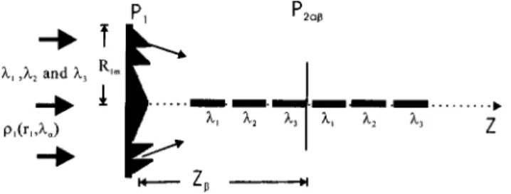
We consider a rotationally symmetric optical system 共see Fig. 1兲 illuminated by a beam with three wavelengths at 1⫽0.6328m, 2⫽0.5145m, and 3⫽0.488m. A DPE is placed at the input plane P1 of the system. The wave function at wavelength␣ on the input plane can be written as
U1,␣⫽U1共r1,␣兲⫽1共r1,␣兲exp关i1共r1,␣兲兴. 共1a兲
The incident light at wavelength␣ passes through the DPE and then propagates in free space. The corresponding wave function at the ’th output plane P2,␣, which is chosen along the optical axis of the system, can be given by
U2,␣⫽U2共r2,␣,z兲
⫽2共r2,␣,z兲exp 关i2共r2,␣,z兲兴. 共1b兲 In a Fresnel approximation, the field distribution on the output plane can be calculated by
U2共r2,␣,z兲⫽
冕
G共r1,r2,␣,z兲U1共r1,␣兲dr1⫽i2
␣zexp共i2z/␣兲exp共ir2 2 /␣z兲 ⫻
冕
0 R1m 1共r1,␣兲 ⫻exp再
i2 ␣关共n␣⫺1兲h共r1兲兴冎
J0冉
2r1r2 ␣z冊
⫻exp共ir12/␣z兲r1dr1, 共2兲 G共r1,r2,␣,z兲⫽ 2 i␣zexp共i2z/␣兲 ⫻exp关i共r1 2⫹r 2 2兲/ ␣z兴J0冉
2r1r2 ␣z冊
.Here J0(2r1r2/␣z) is the zeroth-order Bessel function of the first kind, the coordinate system is chosen such that the z axis is along the optical axis of the system, and r1 and r2 are the radial coordinates on the input and output plane, respectively; R1mis the half diameter of the DPE; n␣ is the refraction index of quartz substrate at wavelength␣; and h(r1) represents the surface-relief depth at the r1 coordi-nate of the DPE. Equation共2兲 can be rewritten in a compact form as
U2共r2,␣,z兲⫽Gˆ共r1,r2,␣,z兲U1共r1,␣兲, 共3兲 where Gˆ represents an integral. For a system with low loss and that satisfies the paraxial approximation, Gˆ is an uni-tary operator, i.e., Gˆ⫹Gˆ⫽Iˆ. In the general case, Gˆ may be not unitary, which means Gˆ⫹Gˆ⫽Aˆ⫽Iˆ, where the superscript⫹indicates the Hermitian conjugation operation, Iˆ is an identity transform, and Aˆ is a Hermitian operator.
In numerical simulation, the continuous function must be represented by a set of discrete sampling points. Assume that the number of sampling points along the radial direc-tion on the input plane is N1. Note Nzis the number of the sampling planes along the optical axis in the output region, N2 is the number of the sampling points along the radial direction on the output plane, and N is the number of the illumination wavelengths. Equations 共1兲 and 共3兲 can be written in matrices as
U1,i␣共r1,i,␣兲⫽1,i␣共r1,i,␣兲
⫻exp关i2共n␣⫺1兲h1共r1,i兲/␣兴, 共4兲 U2,j␣共r2,j,␣,z兲⫽2,j␣共r2,j,␣,z兲 ⫻exp 关i2,j␣共r2,j,␣,z兲兴, 共5兲 U2,j␣共r2,j,␣,z兲⫽
兺
i⫽1 N1 Gˆi j␣共r1,i,r2,j,␣,z兲 ⫻U1,i␣共r1,i,␣兲,where Gˆi j␣(r1,i,r2,j,␣,z) corresponds to an N1⫻N2
⫻N␣⫻Nz matrix and i⫽1,2,3, . . . ,N1, j⫽1,2,3, . . . ,N2,
␣⫽1,2, . . . ,N, and ⫽1,2,3, . . . ,Nz. Here h1,i repre-sents the surface-relief depth at the i’th sampling point of the DPE. Our aim is to find the surface-relief structure h1,i(r1,i) of the DPE that can produce three-color PNDBs characterized by constant and segmented axial-illuminance distributions. In each segment only one color persists. To evaluate the closeness of the calculated wavefront Gˆ U1 to the expected wavefront U2, we introduce the following error function D2. D2⫽
兺
⫽1 Nz兺
␣⫽1 N 兩U2,␣⫺Gˆ␣U1,␣兩2 ⫽兺
⫽1 Nz兺
␣⫽1 N Tr兵U2,⫹␣U2,␣⫺U2,⫹␣Gˆ␣U1,␣ ⫺U1,⫹␣Gˆ␣U2,␣⫹U1,⫹␣A␣U1,␣其 ⫽冉
N1 2冊
⫽1兺
Nz兺
␣⫽1 N冉
兺
j 2,j␣ 2 ⫹兺
l,k 1,i␣1,k␣ Aik j␣ ⫻exp关⫺i共1,i␣⫺1,k␣兲兴⫺兺
j,k 兵2,j␣1,k␣ Gk j␣ ⫻exp关⫺i共2,j␣⫺1,k␣兲兴其⫹c.c.冊
, 共6兲where Aˆ⬅Gˆ⫹Gˆ and c.c. represents complex conjugation. We introduce a phase parameter 0 for a reference wave-length 0, 1,␣ can be represented by 00(n␣
⫺1)/␣(n0⫺1), where n0 is the refractive index at refer-ence wavelength0. The reference wavelength0 and its value are discussed in Sec. 3. Consequently the design problem of the DPE can be formulated as the search for the minimum of D2 with respect to the arguments
0,k, i.e.,
D2/
0,k⫽0. The variation of D2 with respect to 0,k is given by
Fig. 1 Schematic of a diffractive optical system for producing
D2 0,k ⫽Ni 2
兺
 Nz兺
N␣冋
0共n␣⫺1兲 ␣共n0⫺1兲册
冋
兺
i N1再
1,i␣1,k␣Aik j␣⫻exp
冋
⫺i共0,i⫺0,k兲0共n␣⫺1兲 ␣共n0⫺1兲
册
⫺c.c.冎
⫺兺
j N2冉
2,j␣1,k␣Gk j␣ ⫻exp再
⫺i冋
2,j␣⫺0,k 0共n␣⫺1兲 ␣共n0⫺1兲册冎
⫺c.c.冊
册
⫽0. 共7兲 Then we can assumeIm关Qkexp共i0,k兲兴⫽0, 共8兲 where Qk⫽
兺
 Nz兺
N␣冋冉
兺
i N1再
1,i␣Aik j␣exp冋
⫺i0,i0共n␣⫺1兲 ␣共n0⫺1兲
册冎
⫺兺
j N2 关2,j␣Gk j␣exp共⫺i2,j␣兲兴冊
⫻0共n␣⫺1兲 ␣共n0⫺1兲 1,k␣exp再
i0,k冋
0共n␣⫺1兲 ␣共n0⫺1兲⫺ 1册冎
册
. 共9兲Finally, the Eq.共8兲 can be rewritten as
exp关i0,k共n,m⫹1兲兴⫽Q ˜ k *共n,m兲 兩Q˜ k 共n,m兲兩, k⫽1, . . . ,N1, 共10兲 where Q˜k共n,m兲⫽
兺
 Nz兺
N␣冋冉
i兺
⫽k N1再
1,i␣Aik j␣⫻exp
冋
⫺i0,i共n,m兲0共n␣⫺1兲 ␣共n0⫺1兲
册冎
⫺兺
j N2 关2,j␣Gk j␣exp共⫺i2,j␣兲兴冊
⫻0共n␣⫺1兲 ␣共n0⫺1兲 1,k␣ ⫻exp再
i0,k共n,m兲冋
0共n␣⫺1兲 ␣共n0⫺1兲⫺ 1册冎
册
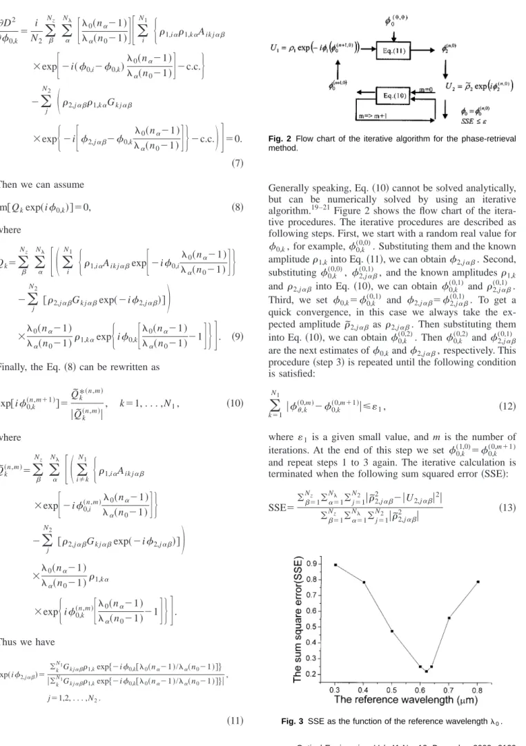
. Thus we have exp共i2,j␣兲⫽ 兺k N1 Gk j␣1,kexp兵⫺i0,k关0共n␣⫺1兲/␣共n0⫺1兲兴其 兩兺k N1G k j␣1,kexp兵⫺i0,k关0共n␣⫺1兲/␣共n0⫺1兲兴其兩 , j⫽1,2, . . . ,N2. 共11兲Generally speaking, Eq.共10兲 cannot be solved analytically, but can be numerically solved by using an iterative algorithm.19–21Figure 2 shows the flow chart of the itera-tive procedures. The iteraitera-tive procedures are described as following steps. First, we start with a random real value for 0,k, for example,0,k
(0,0). Substituting them and the known amplitude1,kinto Eq.共11兲, we can obtain2,j␣. Second, substituting0,k(0,0), 2,j(0,1)␣, and the known amplitudes1,k and2,j␣ into Eq. 共10兲, we can obtain 0,k
(0,1) and 2,j(0,1)␣. Third, we set 0,k⫽0,k (0,1) and 2,j␣⫽2,j␣ (0,1) . To get a quick convergence, in this case we always take the ex-pected amplitude˜2,j␣ as 2,j␣. Then substituting them into Eq.共10兲, we can obtain0,k(0,2). Then0,k(0,2) and2,j(0,1)␣ are the next estimates of0,kand2,j␣, respectively. This procedure共step 3兲 is repeated until the following condition is satisfied:
兺
k⫽1 N1 兩,k共0,m兲⫺ 0,k 共0,m⫹1兲兩⭐ 1, 共12兲where1 is a given small value, and m is the number of iterations. At the end of this step we set 0,k
(1,0)⫽ 0,k (0,m⫹1) and repeat steps 1 to 3 again. The iterative calculation is terminated when the following sum squared error共SSE兲:
SSE⫽兺⫽1 Nz 兺␣⫽1N 兺j⫽1 N2 兩˜2,j2 ␣⫺兩U2,j␣兩2兩 兺⫽1Nz 兺␣⫽1N 兺j⫽1 N2 兩˜2,j␣ 2 兩 共13兲
Fig. 2 Flow chart of the iterative algorithm for the phase-retrieval
method.
reachs minimum, which determines the calculation accu-racy. Finally, the surface-relief profile h1,k, given by Eq.
共14兲, for the DPE can be determined by h1,k⫽
00,k
2共n0⫺1兲, k⫽1,2, . . . ,N1. 共14兲
3 Simulation and Experimental Result
The desired PNDB contains six segments along the optical axis with constant axial illuminance distribution and is
monochromatic in each segment. The first and fourth seg-ments for 1⫽0.6328m correspond to the regions 关120 mm, 170 mm兴 and 关330 mm, 380 mm兴, respectively; the second and fifth segments for 2⫽0.5145m correspond to the regions关190 mm, 240 mm兴 and 关400 mm, 450 mm兴, respectively; the third and sixth segments for 3
⫽0.488m correspond to the regions关260 mm, 310 mm兴
and关470 mm, 520 mm兴, respectively. The parameters used in this design are as follows. The diameter of the DPE and the incident plane-wave beam are 2R1m⫽6.0 mm. The Fig. 4 Comparisons between the transverse illuminance distributions of the simulated PNDB and a
Bessel beam on the sampling plane at (a)z⫽140 mm for wavelength 0.6328m, (b)z⫽210 mm for wavelength 0.5145m, (c) z⫽280 mm for wavelength 0.488 m, (d)z⫽350 mm for wavelength 0.6328m, (e)z⫽420 mm for wavelength 0.5145m, and (f)z⫽490 mm for wavelength 0.488m. Solid curves represent the transverse illuminance distributions of the PNDB generated by the DPE on the sampling planes, and dashed curve represent the illuminance distributions of the zero-order Bessel beam of the first kind.
numbers of sampling points on the input and output planes are N1⫽600 and N2⫽20, respectively. For the calculation of the axial illuminance distribution, the interval ⌬z be-tween the sampling planes must satisfy the sampling condition9 that is given by
⌬z⭐2 z
2
kR1m2 ⫺2z, 共15兲
where k⫽2/ is the wave number of the incident light. Thus the maximum sampling interval that can be deter-mined by Eq.共15兲 is 0.1357 mm. According to the theoret-ical expressions, the number of the sampling points along the optical axis in the output space is Nz⫽3420, and the
sampling interval is ⌬z⫽0.1316 mm in our design. The number of wavelengths for the illumination light is N ⫽3. We assume that the incident wave for each color is plane wave so the illuminance on the DPE is considered to be uniform. In this calculation we find that the reference wavelength0 could affect the final by reached SSE. The results for different0 values are shown in Fig. 3. We can see that we have the best result if the reference wavelength 0 is 0.631m. The output amplitude distribution˜2,j␣is given to be the expected value.
The transverse illuminance distributions of the beam generated by the designed DPE on the each sampling plane are shown in Figs. 4共a兲 to 4共f兲, where the solid curves rep-resent the transverse illuminance distributions of the beam generated by the DPE on the sampling planes, and the dashed curves represent the illuminance distributions of the
zero-order Bessel beam of the first kind. We clearly see that the multisegment beam has a transverse illuminance distri-bution near a Bessel beam distridistri-bution. The deviations in-dicate that the DPE is not real nondiffracting.
To meet the requirement of our fabrication process, the obtained optimum continuous surface profile must be quan-tized in the multilevel structure. Figure 5 shows the surface-relief structures of the DPE in 16 levels. The simu-lation of axial-illuminance distributions with higher sam-pling points generated by the designed 16-level DPE is shown in Fig. 6. From our simulation, we find that N1, Nz,
and0 play important roles in the optimization. There are some restrictions on the two parameters N1 and Nz. For
instance, the minimum feature size permitted for the fabri-cation process determines the upper limit of N1. When the values of N1 and Nz increase, the computation becomes
more complicated. To ensure convergence for the algo-rithm, we relax the restriction of initial condition. In the beginning calculation, we start with a smaller number of sampling points along the optical axis Nz⫽180. Then, we
use more sampling points and substitute the result that is calculated before as initial phase0in the next calculation process. Finally, the number of the sampling points Nz is
increased to 3420 in the last calculation.
The fabrication process of the DPE is as follows. First, four photographic masks共shown in Fig. 7兲 were generated by a laser beam pattern generator共Model HIMT DWL 2.0兲. Then optical contact lithography and reactive-ion etching 共Model AB 1500-series兲 were used to fabricate the surface-relief structures of the DPE on a flat quartz substrate. The minimum feature size of the fabricated element is 10m. Figure 8 shows a photograph of the fabricated DPE and Table 1 shows the etching-depth errors in the etching pro-cess. Figure 9 shows the part of the profile for the surface-relief structure of the fabricated DPE scanned with a Sloan Dektak profilemeter. To check the performance of the fab-ricated DPE, we measured the illuminance distributions on the sampling planes around the optical axis. The experi-mental setup for this measurement is shown in Fig. 10. The illumination beam consists of a He-Ne laser 共0.6328 m兲 and a multiline Argon laser 共0.5145 m, 0.488 m兲. A CCD camera was placed on the optical bench and moved along the optical axis to record the output images on serial sampling planes. The measured axial illuminance distribu-tion is shown in Fig. 11. We also measured the transverse illuminance distributions around the optical axis. The mea-sured results are shown in Figs. 12共a兲 to 12共f兲, measured for 1,2and3at z⫽140 mm located in the first segment, at
z⫽210 mm located in the second segment, at z⫽280 mm
located in the third segment, at z⫽350 mm located in the fourth segment, at z⫽420 mm located in the fifth segment, and at z⫽490 mm located in the sixth segment, respec-tively. These results clearly indicate that the fabricated DPE can produce the desired six-segment three-color PNDBs.
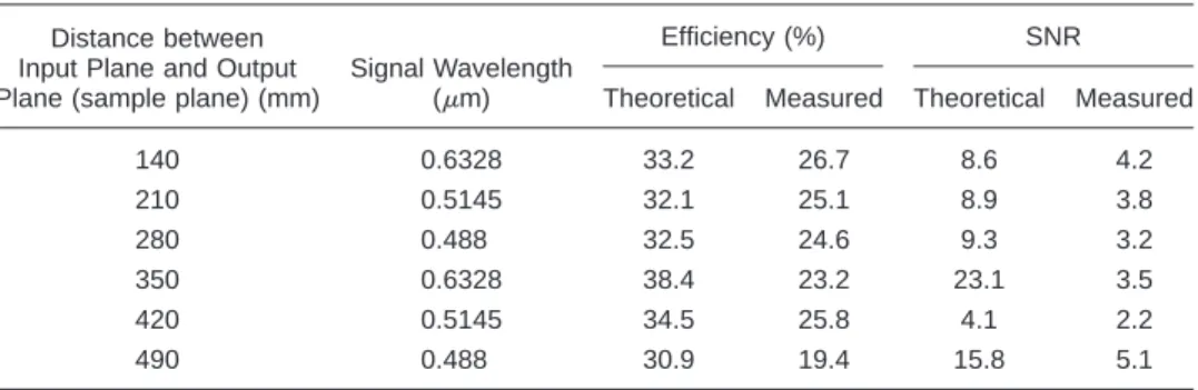
To appraise the performance of the designed DPE, we must calculate the diffraction efficiency and SNR. The dif-fraction efficiency for each wavelength on the sampling plane is defined as
共␣兲⫽signal共␣兲 input共␣兲
, ␣⫽1,2,3, 共16兲
Fig. 5 Distribution of the surface-relief depth of the designed
Fig. 6 Axial-illuminance distribution of the three-color PNDB with six
segments.
Fig. 7 Photographic masks for 16-level DPE: (a) mask 1, (b)
mask 2, (c) mask 3, and (d) mask 4.
Fig. 8 Photograph of the fabricated sample.
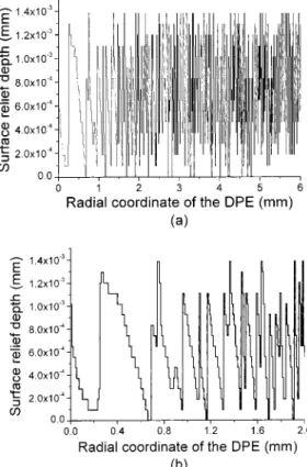
Fig. 9 Section profile of the surface-relief trace of the 16-level DPE
obtained by scanning with a Sloan Dektak profilemeter.
Fig. 10 Experimental setup for measuring the characteristics of the
designed 16-level DPE.
Fig. 11 Measured axial-illuminance distribution generated by the
16-level DPE.
Table 1 Etching-depth errors in the etching process by using
reactive-ion etching (RIE). Theoretical Etching Depth (m) Measured Etching Depth (m) Error Ratio (%) Mask 1 0.738468 0.7599 2.9 Mask 2 0.369234 0.3717 0.6 Mask 3 0.184617 0.1933 0.8 Mask 4 0.092308 0.0953 3.2
Fig. 12 Transverse illuminance distributions for three wavelengths on the sampling plane at (a)z ⫽140 mm, (b)z⫽210 mm, (c)z⫽280 mm, (d)z⫽350 mm, (e)z⫽420 mm, and (f)z⫽490 mm.
whereinput(␣) is the total incident flux at␣on the input plane, andsignal(␣) is the total flux over the signal region on the sampling plane for␣.
The SNR represents the ratio of the signal flux of the wavelength focused in the segment to the flux of the other wavelengths on the same area, and can be expressed as
SNR共␣兲⫽ 兺signalI共r2,signal,␣兲 兺␣⬘⫽␣兺noiseI共r2 noise,␣⬘兲
, ␣⫽1,2,3. 共17兲 Table 2 represents the diffraction efficiency and SNR for each wavelength.
4 Summary
We described the design of a three-color PNDBs in a mul-tiple chromatic illuminating system and showed the results of simulation for the designed DPE. In Fig. 4, the simula-tions show that the transverse illuminance distribution of the PNDB is near to that of a Bessel beam.
The designed 16-level structure DPE has been fabricated on a flat quartz substrate by optical contact lithography and RIE. Experiments show that 6-segment PNDBs can be well formed in the preset regions when a collimated laser beam is used to illuminate the fabricated DPE. The experimental results are in good agreement with the numerical simula-tions, which verifies the design method. Owing to the novel features of the three-color PNDBs, it is expected that the proposed DPE can be useful in applications of precision alignment, display, and optical interconnection in multiple chromatic illuminating systems.
Acknowledgments
The authors gratefully acknowledge the National Science Council of the Republic of China for financial support of this research under Project No. NSC 89-2215-E-009-084, and the Semiconductor Research Center of the National Chiao-Tung University where the DPE was fabricated.
References
1. J. N. Mait, ‘‘Understanding diffractive optic design in the scalar do-main,’’ J. Opt. Soc. Am. A 12, 2145–2158共1995兲.
2. R. Piestun and J. Shamir, ‘‘Control of wave-front propagation with diffractive elements,’’ Opt. Lett. 19, 771–773共1994兲.
3. V. V. Kotiyar, S. N. Khonina, and V. A. Soifer, ‘‘Algorithm for the generation of non-diffracting Bessel modes,’’ J. Mod. Opt. 43, 1231– 1239共1995兲.
4. C. Paterson and R. Smith, ‘‘Higher-order Bessel waves produced by
axicon-type computer-generated holograms,’’ Opt. Commun. 124, 121–130共1996兲.
5. C. Paterson and R. Smith, ‘‘Helicon waves: propagation-invariant waves in a rotating coordinate system,’’ Opt. Commun. 124, 131–140
共1996兲.
6. L. Niggl, T. Lanzl, and M. Maier, ‘‘Properties of Bessel beams gen-erated by periodic gratings of circular symmetry,’’ J. Opt. Soc. Am. A
14, 27–33共1997兲.
7. B.-Z. Dong, G.-Z. Yang, B.-Y. Gu, and O. K. Erosy, ‘‘Iterative opti-mization approach for designing an axicon with long focal depth and high transverse resolution,’’ J. Opt. Soc. Am. A 13, 97–103共1996兲. 8. B. Salik, J. Rosen, and A. Yariv, ‘‘One-dimensional bean shaping,’’ J.
Opt. Soc. Am. A 12, 1702–1706共1995兲.
9. R. Piestun, B. Spektor, and J. Shamir, ‘‘Wave fields in three dimen-sions: analysis and synthesis,’’ J. Opt. Soc. Am. A 13, 1837–1848
共1996兲.
10. R. Piestun, B. Spektor, and J. Shamir, ‘‘Unconventional light distribu-tion in three-dimensional domains,’’ J. Mod. Opt. 43, 1495–1507
共1996兲.
11. V. V. Kotlyar, S. N. Khonina, and V. A. Soifer, ‘‘Iterative calculation of diffractive optical elements focusing into a three-dimensional do-main and onto the surface of the body of rotation,’’ J. Mod. Opt. 43, 1509–1524共1996兲.
12. R. Lieu, B.-Y. Gu, B.-Z. Dong, and G.-Z. Yang, ‘‘Design of diffractive phase elements that realize axial-intensity modulation based on the conjugate-gradient method,’’ J. Opt. Soc. Am. A 15共3兲, 689–694
共1998兲.
13. J. Durnin, J. J. Miceli, Jr., and J. H. Eberly, ‘‘Diffractive-free beams,’’ Phys. Rev. Lett. 58, 1499–1501共1987兲.
14. V. P. Koronkevitch and I. G. Palchikova, ‘‘Kinoforms with increased depth of focus,’’ Optik (Jena) 87, 91–93共1991兲.
15. J. R. Fienup, ‘‘Gradient-search phase retrieval algorithm: for inverse synthetic aperture radar,’’ Opt. Eng. 13, 3237–3242共1994兲. 16. J. Rosen, B. Salik, and A. Yariv, ‘‘Pseudo-nondiffracting beams
gen-erated by radial harmonic functions,’’ J. Opt. Soc. Am. A 12, 2446 – 2457共1995兲.
17. R. Liu, B.-Z. Dong, G.-Z. Yang, and B.-Y. Gu, ‘‘Generation of pseudo-nondiffracting beams with use of diffractive phase elements designed by the conjugate-gradient method,’’ J. Opt. Soc. Am. A 15共1兲, 144 –151共1998兲.
18. R. Liu, B.-Z. Dong, G.-Z. Yang, and B.-Y. Gu, ‘‘Implementation of pseudo-nondiffracting beams by use of diffractive phase elements,’’ Appl. Opt. 37共35兲, 8219–8223 共1998兲.
19. R. Liu, B.-Y. Gu, B.-Z. Dong, and G.-Z. Yang, ‘‘Diffractive phase elements that synthesize color pseudo-nondiffracting beams,’’ Opt. Lett. 23, 633– 635共1998兲.
20. G. Yang, B. Gu, X. Tan, M. P. Chang, B. Dong, and O. K. Ersoy, ‘‘Iterative optimization approach for the design of diffractive phase elements simultaneously implementing several optical functions,’’ J. Opt. Soc. Am. A 11, 1632–1640共1994兲.
21. G. Yang, B. Gu, and B. Dong, ‘‘Theory of the amplitude-phase re-trieval in any linear transform system and its applications,’’ Int. J. Mod. Phys. B 7, 3153–3224共1993兲.
22. G. Z. Yang, B. Z. Dong, B. Y. Gu, J. Y. Zhuang, and O. K. Ersoy, ‘‘Gerchberg-Saxton and Yang-Gu algorithms for phase retrieval in a nonunitary transform system: a comparison,’’ Appl. Opt. 33, 209–218
共1994兲.
Table 2 Theoretical and measured diffraction efficiencies and SNRs for each wavelength. Distance between
Input Plane and Output Plane (sample plane) (mm)
Signal Wavelength (m)
Efficiency (%) SNR
Theoretical Measured Theoretical Measured
140 0.6328 33.2 26.7 8.6 4.2 210 0.5145 32.1 25.1 8.9 3.8 280 0.488 32.5 24.6 9.3 3.2 350 0.6328 38.4 23.2 23.1 3.5 420 0.5145 34.5 25.8 4.1 2.2 490 0.488 30.9 19.4 15.8 5.1
Jyh-Rou Sze received his BS degree in 1997 from the Department of Electrical-Engineering, Private Chinese-Culture Uni-versity, and his MS degree in 1999 from the Department of Electro-Optical Engi-neering, Nation Chiao-Tung University, where he is currently working toward his PhD degree. His current interests include numerical methods applied to design dif-fractive optical elements that have a par-ticular function and to fabricate the de-signed elements.
Mao-Hong Lu graduated from the Depart-ment of Physics, Fudan University, in 1962. He was then a research staff member with the Shanghai Institute of Physics and Tech-nology, Chinese Academy of Sciences, from 1962 to 1970, and with the Shanghai Institute of Laser Technology from 1970 to 1980. He studied at the University of Ari-zona as a visiting scholar from 1980 to 1982. He is currently a professor with the Institute of Electro-optical Engineering, Na-tion Chiao-Tung University.