透過802.11b WLAN來增進GPRS的傳輸速率
87
0
0
全文
(2) 透過 802.11b WLAN 來增進 GPRS 的傳輸速率 Increasing GPRS Data Transfer Throughput via The Assistance of WLAN. 研究生: 蔡宏儒. Student : Hung-Ju Tsai. 指導教授: 王協源. Advisor : Shie-Yuan Wang. 國 立 交 通 大 學 資訊工程系 碩士論文. A Thesis Submitted to Department of Computer Science and Information Engineering College of Electrical Engineering and Computer Science National Chiao Tung University in partial Fulfillment of Requirements for the Degree of Master in Computer and Information Science June 2005 Hsinchu, Taiwan, Republic of China. 中華民國九十四年六月.
(3) 中文摘要 近來由於網路的普及, 許多使用者需要隨時隨地的使用網路資源. 舉例來說, 使用者可能剛好在戶外卻突然要收發一個緊急的 email.當人們遠離他們的辦公室 或是家裡時, 可以利用廣域的 GPRS 網路來持續的使用網路. 然而一個 GPRS 頻 道所提供的頻寬卻是非常的低. 除了 GPRS 網路, 3G 網路也可以提供廣域的服務 和更高的頻寬. 但是不幸的, 在發表本篇論文時, 市場上還沒有 3G 的產品.. 在本篇論文中, 我們提出了一個方法可以增加 GPRS 使用者的檔案傳輸速率. 我們的方法是利用多條的 GPRS 頻道來平行下載檔案. 使用網路服務的使用者除 了利用自己的 GPRS 頻道下載資料外, 同時間也利用其他鄰近的 GPRS 頻道來幫 助下載. 當鄰近的 GPRS 頻道收到資料封包後, 這些鄰近的 GPRS 頻道會利用 802.11b 無線網路來傳送收到的資料封包給要求網路服務的那一位使用者.. 我們設計並實作出上述的方法. 且我們的系統並不需要 GPRS 業者的任何支 援. 我們量測了此系統再真實世界的表現. 實驗結果顯示在同時有四個 GPRS 頻 道平行下載情況中, 我們的系統可以達到約原本傳輸速率的 2.7 倍. 為了量測我 們系統在更複雜的拓撲和移動的情形下之表現. 我們使用 NCTUns2.0 模擬器, 模擬並量測系統的表現.. III.
(4) Abstract Recently the Internet becomes more and more popular. Users may need Internet access everywhere. For example, one may need to browse a web page or want to send/receive emails outdoors. To remain connected to the Internet, people may use wide-area GPRS networks when they are away from their home and office networks. A GPRS channel, however, provides very little bandwidth. Excepting a GPRS network, a 3G network is another choice that provides much higher bandwidth. Unfortunately, a 3G network has not put to market yet.. In this paper, we propose a scheme to increase the file transfer throughput for a GPRS user. Our approach is to transfer a requested file over multiple GPRS channels in parallel. The requesting user uses one’s channel and those of one’s neighbors for the transfer. When receiving packets from their GPRS channels, these neighbors forward them to the requesting user through a mobile ad-hoc network (MANET) using IEEE 802.11 (b) WLAN interfaces.. We have designed and implemented our scheme. Our scheme can be deployed for a real-world GPRS network without any support from it. We have evaluated the performance of our scheme on a real-world GPRS network. Our experimental results show that our scheme achieves about 2.7X speedup over 4 GPRS channels. To further evaluate our scheme with a much complicated topology, we have simulated our scheme and evaluated the performance of it on network simulator NCTUns2.0.. IV.
(5) 致 謝 首先,感謝恩師王協源教授二年來對我的悉心指導,由於 老師給我們的扎實訓練,研究所這二年讓我在專業領域上 獲益良多。. 感謝吳暁光教授以及賴威光教授撥冗來到交通大學進行口 試,以及對論文的建議,讓這篇論文更加完善。. 感謝網路與系統實驗室的所有成員,因為有你們的陪伴以 及彼此間的協助,讓我在研究所二年不僅學到很多,生活 也很充實快樂。. 感謝許多朋友的幫忙與陪伴,如以前的大學同學和室友, 清大管樂社的學長學弟等,和一旁默默陪伴的嫚綺,讓我 在新竹的生活能順利又愉快。. 最後感謝父母的支持,一路走來陪伴我,讓我在求學過程 中順暢無後顧之優能專心於學業之中。 V.
(6) Table of Contents 1. Introduction………………………………………………………………………..1 2. Related Work………………………………………………………………………3 3. System Design and Implementation ….…………………………………………...7 3.1 System Architecture…………………………………………………………...7 3.2 System Implementation………………………………………………………..9 3.2.1 Trunk Daemon and Web Proxy Server………………………………...9 3.2.2 Mobile Node Daemon and Application………………………………13 4. Protocol Design…………………………………………………………..………15 4.1 Initialization Protocol…………………………………………………...……16 4.2 Data Transfer Protocol………………………………………………….……20 4.2.1 Improvement of Acknowledgement…………………………….……21 4.2.2 Fast Retransmission in our scheme…………………………………..22 4.2.3 Improved Fast Retransmission in our scheme………………….…….22 4.3 Ad-Hoc Routing Protocol………………………………………………..…...23 4.3.1 Mobility Issues……………………………………………………….23 4.4 Reset Protocol…………………………………………………………….….24 5. Experimental Settings and Results…………………………………………….…25 5.1 Experimental Settings………………………………………………………..26 5.2 Experimental Results…………………………………………………………29 5.2.1 Calibration Tests……………………………………………………...29 5.2.2 Evaluation Experiments……………………………………………...33 6. Simulation Settings and Results………………………………………………….39 6.1 Simulation Settings and Modifications………………………………………40 6.2 Simulation Results…….……………………………………………………...40 6.2.1 Calibration Tests for the GPRS package on NCTUns2.0…………….40 6.2.2 Evaluation Experiments with a Simple Wireless Physical Layer Module……………………………………………………………….44 6.2.2.1 TCP………………………………………………………………44 6.2.2.1.1 Single Hop Count……………………………………...…44 6.2.2.1.2 Multiple Hop Counts…………………………………..…52 6.2.2.2 UDP………………………………………………………………53 6.2.2.2.1 Single Hop Count………………………………………...53 6.2.2.2.2 Multiple Hop Counts……………………………………..60 6.2.3. Evaluation Experiments with an Advanced Wireless Physical Layer Module……………………………………………….………………61 6.2.3.1 TCP………………………………………………………………61 VI.
(7) 6.2.3.1.1 Single Hop Count………………………………………...62 6.2.3.1.2 Multiple Hop Counts……………………………………..63 6.2.3.2 UDP………………………………………………………………65 6.2.3.2.1 Single Hop Count………………………………………...65 6.2.3.2.2 Multiple Hop Counts……………………………………..66 6.3 Routing Experiments…………………………………………………………66 6.3.1 Basic Routing Experiments…………………………………………..66 6.3.2 Integrated Experiment………………………………………………..68 7. Discussions……………………………………………………………………….70 7.1 Market Potential……………………………………………………………...70 7.2 Billing Issues…………………………………………………………………71 8. Future Work………………………………………………………………………72 9. Conclusions………………………………………………………………………73 References……………………………………………………………………………74 Appendix…………………………………………………………………………….76. VII.
(8) List of Figures Figure 3.1: The high-level system architecture………………………………………..9 Figure 3.2.1-1: The trunk daemon sets firewall rules to intercept and dispatch packets to the DN and its helping RNs……………………………………………………….10 Figure 3.2.1-2: the data structure of our acknowledgement scheme…………………12 Figure 3.2.2: The mobile node daemon reorders out-of-order packets, and then sends them to the web browser through a raw socket………………………………………14 Figure 4.1-1: the initialization protocol (1)…………………………………………..17 Figure 4.1-2: the initialization protocol (2)…………………………………………..18 Figure 4.1-3: the initialization protocol (3)…………………………………………..20 Figure 4.2: The data transfer protocol………………………………………………..21 Figure 4.3.1: a moving motorcade…………………………………………………...24 Figure 4.4: The reset protocol………………………………………………………..25 Figure 5.1-1: The trunk daemon……………………………………………………...27 Figure 5.1-2: Four notebook computers are used in experiments. One of them is used as the DN while the others are used as the DN’s helping RNs………………………27 Figure 5.1-3: Each notebook computer is equipped with an IEEE 802.11(b) WLAN interface card and a GPRS interface card…………………………………………….28 Figure 5.2.1-1: The throughput of one GPRS channel……………………………….31 Figure 5.2.1-2: The throughputs of two GPRS channels…………………………….31 Figure 5.2.1-3: The throughputs of three GPRS channels…………………………...32 Figure 5.2.1-4: The throughputs of four GPRS channels…………………….………32 Figure 5.2.2-1: The average file download throughput with different sizes (through only one GPRS channel)……………………………………………………………..34 Figure 5.2.2-2: The average file download throughput with different sizes (through two GPRS channels)………………………………………………………………….35 Figure 5.2.2-3: The average file download throughput with different sizes (through three GPRS channels)………………………………………………………………...36 Figure 5.2.2-4: The average file download throughput with different sizes (through four GPRS channels)…………………………………………………………………36 Figure 5.2.2-5: experiment results in the real world…………………………………38 Figure 5.2.2-6: experiment speedup in the real world ……………………………….39 Figure 6.2.1-1: simple topology of GPRS network…………………………………..41 Figure 6.2.1-2: the protocol stacks of base station……………….………………..42 Figure 6.2.1-3: GPRS TCP Throughput……………………………………………...43 Figure 6.2.1-4: GPRS UDP Throughput……………………………………………..43 Figure 6.2.2.1.1-1: simulation topology 1……………………………………………45 VIII.
(9) Figure 6.2.2.1.1-2: GPRS TCP Throughput………………………………………….45 Figure 6.2.2.1.1-3: GPRS TCP Throughput – One Relay……………………………46 Figure 6.2.2.1.1-4: GPRS TCP Throughput – Two Relay……………………………47 Figure 6.2.2.1.1-5: GPRS TCP Throughput – Three Relay…………………………..47 Figure 6.2.2.1.1-6: GPRS TCP Throughput – Four Relay…………………………...48 Figure 6.2.2.1.1-7: TCP Traffic Flow – Four Relay………………………………….49 Figure 6.2.2.1.1-8: GPRS TCP Throughput – Five Relay……………………………49 Figure 6.2.2.1.1-9: TCP Traffic Flow – Five Relay………………………………….50 Figure 6.2.2.1.1-10: GPRS TCP Throughput – Six Relay…………………………...51 Figure 6.2.2.1.1-11: TCP Traffic Flow – Six Relay………………………………….51 Figure 6.2.2.1.1-12: TCP throughput – One Hop…………………………………….52 Figure 6.2.2.1.2-1: simulation topology 2……………………………………………52 Figure 6.2.2.1.2-2: TCP throughput – Multiple Hops………………………………..53 Figure 6.2.2.2.1-1: GPRS UDP throughput…………………………………………..54 Figure 6.2.2.2.1-2: GPRS UDP throughput – One Relay…………………………….55 Figure 6.2.2.2.1-3: GPRS UDP throughput – Two Relay……………………………55 Figure 6.2.2.2.1-4: GPRS UDP throughput –Three Relay…………………………...56 Figure 6.2.2.2.1-5: GPRS UDP throughput – Four Relay……………………………57 Figure 6.2.2.2.1-6: UDP Traffic Flow – Four Relay………………………………....57 Figure 6.2.2.2.1-7: GPRS UDP throughput – Five Relay……………………………58 Figure 6.2.2.2.1-8: UDP Traffic Flow – Five Relay………………………………….58 Figure 6.2.2.2.1-9: GPRS UDP throughput – Six Relay……………………………..59 Figure 6.2.2.2.1-10: UDP Traffic Flow – Six Relay…………………………………59 Figure 6.2.2.2.1-11: UDP throughput – One Hop……………………………………60 Figure 6.2.2.2.2-1: UDP throughput – Multiple Hops……………………………….61 Figure 6.2.3.1.1-1: simulation topology 3……………………………………………62 Figure 6.2.3.1.1-2: TCP throughput (AWPHY) – One Hop………………………….63 Figure 6.2.3.1.2-1: simulation topology 4……………………………………………64 Figure 6.2.3.1.2-2: TCP throughput (AWPHY) – Multiple Hops……………………64 Figure 6.2.3.2.1: UDP throughput (AWPHY) – One Hop…………………………...65 Figure 6.2.3.2.2: UDP throughput (AWPHY) – Multiple Hops……………………..66 Figure 6.3.1-1: basic routing topology……………………………………………….67 Figure 6.3.1-2: TCP throughput of the basic routing experiment……………………68 Figure 6.3.2-1: integrated experiment topology……………………………………...69 Figure 6.3.2-2: TCP throughput of the integrated experiment……………………….70 Figure A-1: experiment results in the real world…………………………………….76 Figure A-2: experiment speedup in the real world…………………………………. .76 Figure A-3: GPRS TCP Throughput…………………………………………………76 IX.
(10) Figure A-4: GPRS UDP Throughput…………………………………………………77 Figure A-5: TCP throughput of the basic routing experiment………………………..77 Figure A-6: TCP throughput of the integrated experiment…………………………...77. X.
(11) 1. INTRODUCTION GPRS (General Packet Radio Service) is a data service that allows information to be sent and received across a mobile telephone network. In such a network, the transmission distance between a base station and a mobile device can range from hundreds of meters to thousands of meters. GPRS is wide-area and conveniently available in indoor and outdoor places covered with a base station’s signal.. Although GPRS provides several advantages such as high availability and support for high mobility, a GPRS user, however, receives very little transfer throughput over a GPRS channel. In Taipei city, average throughput of GPRS is 3.5 Kbytes. The maximum download/upload throughput achieved is only 36/12 Kbps using the common 3+1 package, where 3 and 1 time slots are allocated to downlink and uplink traffic, respectively. On such a low-bandwidth network, applications that demand high bandwidth will not perform satisfactorily.. In this thesis, we propose a scheme to increase the file download throughput for a GPRS user. The main idea is to download a requested file over multiple GPRS channels in parallel. If a user wants to download a large file through the GPRS network (this user is called the request originator in the following description), he would ask for bandwidth support from his neighboring users. Those neighboring users who are willing to help and are not using their GPRS bandwidth use their GPRS channels to help download the file. The requested file then is downloaded over these GRRS channels in parallel. When receiving packets from these GPRS channels, these helpers forward them to the request originator through a mobile ad-hoc network (MANET) using IEEE 802.11 (b) WLAN interfaces. Since the bandwidth of an IEEE -1-.
(12) 802.11(b) interface is 11 Mbps, which is much larger than the bandwidth of a GPRS channel, the request originator can simultaneously receive these packets without congestion. By this scheme, the time required for downloading a large file over a GPRS network can be reduced. We design this scheme for the user both on a wide area network with low bandwidth and long latency such as GPRS network and on a local area network with high bandwidth and short latency such as IEEE 802.11(b) network.. The design and implementation of our scheme can be readily deployed for a real-world GPRS network without any support from it. In our scheme, only two daemon programs and one slightly modified web proxy server (Apache) need to be run. One daemon program is run on the mobile host. The other daemon program and the web proxy server are run on an Internet host, which can be located in any subnet of the Internet. According to our experimental results, on average, about 2.7X throughput speedup can be achieved over 4 GPRS channels. We also evaluated our scheme about some issues such as mobility support in MANET on NCTUns2.0 [11].. Recently, cellular phones equipped with GSM/GPRS and WLAN interfaces have been introduced to the market. Such phones have the required network interfaces to use our scheme. Since our scheme can be readily deployed for a real-world GPRS network, before expensive 3G networks and services are widely deployed, our scheme provides a low-cost solution for GSM/GPRS network operators to use their current 2.5G networks to provide high-bandwidth applications for such phones.. In the rest of this paper, we first survey related work in Section 2. Then we introduce the design and implementation of our scheme in Section 3. In Section 4, we -2-.
(13) describe the protocol designs of our scheme in detail. In Section 5, we presented the experimental settings and results. In Section 6, we presented the simulation settings and results on NCTUns2.0.. In Section 7, we discuss some issues of our scheme. In. Section 8, we point out future work. Finally, Section 9 concludes this paper.. 2. RELATED WORK. In the literature, several approaches have been proposed to integrate WLAN and GPRS networks to achieve better performance [1, 2, 3, 4, 5, 6, 7, 8, 9, 10]. We categorize those approaches into three different groups.. We group UCAN [1], an approach [5], and 7DS [10] into the first category. Protocols in this category transmit users’ data without using parallel transmission mechanism. Those protocols extend GPRS network coverage or always download data using one better GPRS channel quality by integrating WLAN and GPRS networks.. UCAN [1] also aims to reduce the file download time over a GPRS network. In UCAN, a download request originator, called the destination node, chooses a neighboring node whose GPRS channel’s quality is better than that of its own channel to be its proxy node. When the destination node wants to download a large file through the GPRS network, it informs the base station of its proxy node. After receiving this information, the base station sends the requested file to the proxy node through its GPRS channel. The proxy node then forwards the packets of this file to the. -3-.
(14) destination node through a MANET.. The motivation for proposing UCAN is that a low-throughput file transfer is mainly due to the use of a low-quality GPRS channel; therefore, finding another channel with a better quality to download the file can improve the file transfer throughput for a destination node that has a low-quality channel. Although in UCAN both GPRS and WLAN are used (which is similar to our scheme), only one GPRS channel is used to download a requested file at any time. This is different from our multi-channel scheme and it limits the maximum achievable download throughput to be a GPRS channel’s bandwidth. Moreover, supports from the GPRS network are needed to modify base stations in UCAN whereas in our scheme this is unnecessary.. In the approach [5], the authors attempt to improve the reliability of coverage in cellular networks. Its design extends a mobile phone call by employing an intermediary to carry this call. Thus, a mobile phone call may become a 2-hop call. The intermediary can be a mobile device or a vehicle with sufficient power resources. A MANET is employed to achieve better reliability in a cellular network; however, it may increase the intra-cell interference. The goals, design, and implementation of this scheme are different from those of our scheme.. In 7DS [10], the authors use the concept of peer-to-peer scheme. Once a user downloads data from a GPRS network, all the other users in the formed Ad-Hoc network can retrieve the data from this user in MANET.. We group an approach [2], iCAR [3], and MADF [4] into the second category. Protocols in this category also transmit users’ data without using parallel transmission -4-.
(15) mechanism. Those protocols improve the performance of GPRS base station by using Ad-Hoc network.. In [2], the authors proposed a mechanism for smooth handovers between WLAN and GPRS networks. The authors defined the area reachable from a base station in single hop as a cell. If the source node and the destination node stay in the same cell, the packets sent from the source node to the destination node need not pass through the base station. Instead, other mobile nodes located in the same cell use a MANET to relay these packets. In this case, a multi-hop routing mechanism has to be involved. If the source node and destination node do not stay in the same cell, the source node first sends its packets to the base station with which it is associated. Then the packets are forwarded to the base station with which the destination node is associated through the GPRS backbone network. Finally, the destination node receives the packets through its GPRS channel. The transmission path between the source node and its associated base station may be one-hop (using GPRS) or multi-hop (using MANET), so is the path between the destination node and its associated base station. This approach aims to smoothly switch the transmission path between a WLAN and a GPRS networks. Its goal, design, and implementation are different from those of our scheme.. In iCAR [3], some ad hoc relay stations (ARSs) are placed at strategic locations so that a mobile host’s packets can be relayed by these ARSs to a base station that is not the mobile node’ associated base station. If a cell has a heavy traffic load and its adjacent cells do not have heavy loads, a mobile host’s packets can be diverted from its cell to an adjacent cell so that its cell’s congestion is reduced. The iCAR approach can reduce the call blocking probability for circuit-like traffic by diverting traffic from -5-.
(16) heavily-loaded cells to nearby lightly-loaded cells. Since a mobile host still uses only a channel in iCAR, the goal, design, and implementation of iCAR are different from those of our scheme.. Another system is MADF [4]. The authors defined a cell with a heavy traffic load as a hot cell while a cell with a light traffic load as a cold cell. MADF proposes a dynamic channel allocation scheme that assigns more channels to hot cells. In MADF, ad-hoc overlay devices are employed and located at the places between hot cells and cold cells. Users in hot cells can connect to adjacent cold cells through these ad-hoc relay devices over specific channels. MADF prevents packet delay from increasing in a cell with a heavy traffic load. This approach attempts to overcome congestions within a heavily-loaded cell. It is different from our multi-channel scheme.. We group pTCP [6], MAR [9], MC2 [8], and MoPED [7] into the third category. Protocols in this category transmit users’ data using parallel transmission mechanism. pTCP [6] is an end-to-end transport layer protocol for striped connections. It modifies TCP protocol for parallel transmission, so users can operate their protocol not only on a GPRS network. However, pTCP is not transparent to users, because users must modify their kernel in this approach.. In MAR [9], authors implement a computer router infrastructure for the mobile Internet, called MAR router. The MAR router can connect to heterogeneous networks such as a GPRS network or an 802.11b infrastructure network at the same time. Therefore, the MAR router can download data in parallel for the users who connect to the MAR router. In their scheme, the authors modify kernels of the MAR router and the MAR Server Proxy. In MAR, users must be close to the MAR router, and users’ -6-.
(17) transmission speed is limited by the bandwidth of their endpoint device.. In MC2 [8], and MoPED [7], their approaches are similar. Those two approaches both are about intelligent bandwidth aggregation. The main idea of MC2 or MoPED is to download a requested file over multiple channels in parallel. Although, the main idea of our scheme is similar to MC2 and MoPED, their approaches don’t study mobility issues as well as ours.. In this paper, we propose a multi-channel scheme to improve the file download throughput over a GPRS network. The design and implementation of our scheme do not require any support from the GPRS cellular network. Moreover, our scheme supports mobility in MANET that all approaches above seldom mention about.. 3. SYSTEM DESIGN AND IMPLEMENTATION 3.1 System Architecture A high-level architecture of our scheme is depicted in Figure 3.1, which shows the components of the whole system. The functionalities of each component are described below: . Web Server (WS): WS is a content provider that provides data for users. It can be any on-line information server on the Internet such as a ftp server.. . Proxy Server (PS): PS is a slightly-modified proxy server that retrieves a requested file from a WS on behalf of a user. In our scheme, a daemon program (called the trunk daemon) runs on the same machine as the PS. It intercepts the packets sent from the PS to the user and sends them over multiple GPRS channels to the DN and its helping RNs (see their definitions below). -7-.
(18) . Relay Node (RN): RN is a node that does not use its GPRS channel for itself but instead uses its channel to help download data for the Destination Node (see its definition below).. . Destination Node (DN): DN is a node that uses GPRS channels to download a file (e.g., a web page) from the Internet. The requested file is downloaded via the DN’s own channel and the channels of its helping RNs. After receiving packets carrying the content of the requested file from GPRS channels, these RNs relay them to the DN through a mobile ad-hoc network.. Both DN and RN need to learn the existence and channel quality of its neighboring nodes. It periodically exchanges hello packets with its neighboring nodes to collect such information.. A simple example is given below to illustrate how the system works. Both DN and MN should set PS as their proxy server at first. In Figure 3.1, when the DN wants to download a web page from the WS located on the Internet, it sends a HTTP web request to the PS through its GPRS channel. After DN receives an indication packet from the modified Apache in PS, it sends the information regarding its neighboring nodes to the trunk daemon so that the trunk daemon can select some of them as the helping RNs for this DN. After the PS has retrieved the requested web page, it sends the web page to the DN. The trunk daemon intercepts these packets and then sends them over the GPRS channels of the DN and its helping RNs using a round-robin scheduling method. These RNs relay their received packets to the DN through the mobile ad-hoc network. Finally, the DN receives, re-sequences, and delivers all packets of the requested web page to the web browser, which then displays the downloaded file on the screen or saves it into a disk. Users through our scheme can -8-.
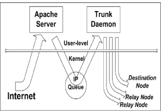
(19) download their files more quickly.. Figure 3.1: The high-level system architecture.. 3.2 System Implementation. 3.2.1. Trunk Daemon and Web Proxy Server. In the following, we present how to use our scheme to download a requested file to a DN over multiple GPRS channels. In Figure 3.2.1-1, the apache server is the proxy server (PS) in our scheme. After a DN initiates a web request over its GPRS channel, the content of the requested file comes back from the designated WS over an Internet path shown on the left. After receiving the file, the apache server sends the file’s content to the DN using the DN’s IP address assigned by the GPRS network as the destination IP addresses of these packets.. -9-.
(20) The trunk daemon installs several firewall rules in the kernel during the initialization protocol mentioned after, before the apache server receives the file request. These firewall rules instruct the firewall facility in the kernel to intercept the data packets that will be sent from the apache server to the DN. Packets captured by these rules are enqueued into the IP queue in the kernel. The trunk daemon will dequeue them from the IP queue and then dispatch them to the DN and to its helping RNs through their GPRS channels in a round-robin scheduling order. Our scheme does some optimizations in a common round-robin scheduling algorithm, such like trunk daemon doesn’t dispatch data packets to a RN with bad GPRS link quality.. Figure 3.2.1-1: The trunk daemon sets firewall rules to intercept and dispatch packets to the DN and its helping RNs.. The trunk daemon sends the captured data packets (TCP packets when using HTTP protocol or FTP protocol) to the DN and its helping RNs through a UDP socket. This means that these packets are encapsulated as UDP packets when they travel on. - 10 -.
(21) GPRS channels. When sending a UDP packet to the DN or a RN, the trunk daemon uses the IP address of the receiving machine assigned by the GPRS network as the destination IP address of the packet. Doing so enables the packet to be sent over the receiving machine’s GPRS channel. The trunk daemon retransmits a UDP packet if it detects that the packet is lost on a GPRS channel or on a MANET link. It implements an acknowledgement scheme running between itself and a DN or a RN to detect packet losses.. z. Acknowledgement Scheme between a trunk daemon and mobile nodes. In the trunk daemon, it implements an acknowledgement scheme like TCP protocol. There is a sliding window of every mobile node such as a DN and a RN in the trunk daemon, and a destination packets queue of every DN in the trunk daemon (Figure 3.2.1-2).. A simple example is given below to illustrate how the acknowledgement scheme works. When the trunk daemon dequeues a data packet from IP queue, it first try to send out this data packet through a DN or RN without a full sliding window by Round-Robin scheduling scheme, and maintain a copy of this data packet in the DN’s or RN’s sliding window in case of retransmission. If it can find out any DN or RN without a full sliding window, the trunk daemon will enqueue this packet back to the destination packet queue. The trunk daemon will dequeue this packet and send it out once any DN or RN without a full sliding window.. The trunk daemon enqueues the data packet into destination packet queue directly, if there is any data packet in destination packet queue. By Doing so, the trunk - 11 -.
(22) daemon can maintain data packets enqueued in the destination packet queue in order. Every DN or RN sends an ACK packets back to the trunk daemon, when it receives a data packet dispatched from the trunk daemon. The trunk daemon will delete the related data packet copy in the DN’s or RN’s sliding window, as it receives an ACK packet.. Figure 3.2.1-2: the data structure of our acknowledgement scheme. The apache server is slightly modified to make our system work correctly. When apache server receives an HTTP request from a DN, it immediately sends a reply back to notify DN that it’s time to send the table of its neighboring nodes. When the requested file has been downloaded to the DN, it notifies the trunk daemon of the completion of the file transfer. The trunk daemon then removes the firewall rules that were previously installed in the kernel and releases used data structures and other resources.. - 12 -.
(23) 3.2.2 Mobile Node Daemon and Application. The mobile node daemon is executed on each mobile node equipped with a GPRS and an IEEE 802.11 (b) WLAN interfaces. In our scheme, a mobile node daemon may perform the function of a DN or a RN. This is because when a RN is relaying packets for a DN, it may want to become a DN to download its own file. On the other hand, When a DN finishes downloading its own file, it may be asked to be a RN for another DN.. Every DN or RN broadcasts a hello packet periodically, so it knows its neighboring nodes. By our routing scheme, every neighboring DN or RN can share its table of neighboring nodes. Therefore, it can know other RN cross multiple hops in MANET. This information helps a mobile node daemon choose its RN candidates when it becomes a DN. The mobile node daemon also functions as a routing daemon using our routing scheme on the IEEE 802.11(b) MANET. With the routing tables built by our routing scheme, a routing path between a RN and a DN can be set up. On a mobile node, several real-world applications such as the Mozilla web browser can be used to download files. They function normally and take advantage of our scheme without any modification. When the web browser initiates a web request, the mobile node will become a DN and the request is sent over this mobile node’s GPRS channel to the PS. Later on, the packets carrying the content of the requested file are sent back to the DN through its own GPRS channel or through some ad-hoc links in the IEEE 802.11(b) MANET. This is shown in Figure 3.2.2.. - 13 -.
(24) Figure 3.2.2: The mobile node daemon reorders out-of-order packets, and then sends them to the web browser through a raw socket.. If a mobile node daemon plays the role of a RN, it just needs to relay received packets that are sent from the trunk daemon to the DN via it. When relaying a packet to the DN, it sends out the packet through a UDP socket in MANET. The destination IP address of this packet is set to be the IP address of the DN configured on the MANET. As such, the packet is encapsulated as a UDP packet and travels on the MANET until it reaches the DN. The mobile node daemon implements an acknowledgement scheme running between itself and the DN to detect packet losses that occur on the MANET. If any packet is lost on the MANET, it retransmits the packet until the DN eventually receives the packet.. If a mobile node daemon plays the role of a DN, it may need to reorder received packets, which may be out-of-order because they traverse on different GPRS channels and on different MANET paths. The mobile node daemon reorders these packets into the correct order and then writes them into the kernel through a raw socket. From the viewpoint of the kernel, these packets appear to arrive from a normal network - 14 -.
(25) interface such as an Ethernet interface. As such, these packets pass through the TCP/IP protocol stack in the kernel and are enqueued into a TCP socket used by the web browser. Finally, the web browser reads the TCP socket to get the content carried by these packets. It may display the content on the screen or save the content into the disk.. z. Re-order packets in a DN. The trunk daemon gives every data packet a different sequence number which begins at number 1. If a data packet is sent from a different application such as a FTP client, the trunk daemon will re-give the data packet a different sequence number which begins at number 1. Doing so, DN can reorder data packets from different applications separately.. A DN won’t dequeue packets in its reordering queue and send to an application through raw socket when those packets are not in order. However, DN can’t queue a packet in the reordering queue too long a time, so DN sets a timer for every packet in the reordering queue. A DN sends the timeout packet to an application through raw socket without waiting.. 4. PROTOCOL DESIGNS. The protocols used in our scheme include the initialization, data transfer, MANET routing, and reset protocols. The first goal of the protocol design is that a real-world - 15 -.
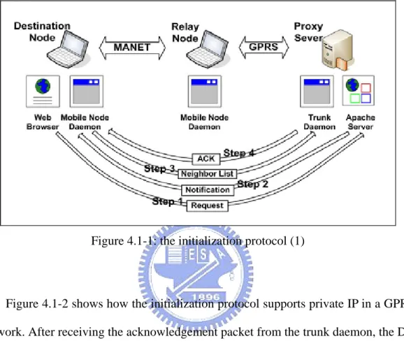
(26) application, such as a web browser or a FTP client program, should be able to benefit from our scheme on a mobile node without any modification. The second goal is that our scheme can be deployed for any real-world GPRS network without any support from it. For example, in our experiments, we tested two commercial GPRS networks that are provided by different operators (ChungHwa and FarEastone) and found that one assigns public IP addresses to its GPRS users while the other assigns private IP addresses to its GPRS users. In this case, we would like our scheme to work successfully for both types of GPRS networks. Our scheme achieves these goals. The third goal is that our routing scheme can support the mobility in MANET. We describe the details of each protocol in the rest of this section.. 4.1 Initialization Protocol. The initialization protocol coordinates the different parts of the system so that they work together to download a requested file over multiple channels. In the following, we use an example to illustrate the protocol step by step. In Figure 4.1-1, a web browser on the DN sends a request to the apache server (PS) (step 1). The apache server then sends a notification packet to the mobile node daemon running on the DN (it will be simply called the “DN” for brevity in the following description when there is no ambiguity) to inform it that a web browser executed on the same node has initiated a web transfer request (step 2). In the meantime, the apache server (acting as a proxy server) sends the request to the designated WS on behalf of the DN to retrieve the requested file. Because each mobile node daemon maintains the information about its neighboring nodes, the DN sends a list of its neighboring nodes to the trunk daemon (step 3). The nodes on the list are RN candidates for this DN and the trunk. - 16 -.
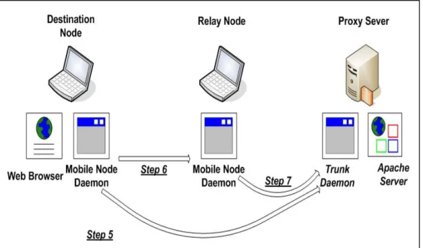
(27) daemon may select some of them as the helping RNs for this DN based on their willingness and channel quality. The trunk daemon then sends an acknowledgement packet back to the DN (step 4).. Figure 4.1-1: the initialization protocol (1). Figure 4.1-2 shows how the initialization protocol supports private IP in a GPRS network. After receiving the acknowledgement packet from the trunk daemon, the DN sends a “NAT Mapping Installation” packet to the trunk daemon (step 5). If the GPRS network uses a network address translator (NAT) and assigns private IP addresses to its GPRS users, when this packet passes through the GPRS network’s NAT on its way to the PS, the NAT will install a mapping entry recording the mapping between the packet’ s private IP address and port number used inside the GPRS network and the public IP address and port number assigned to it. With this mapping entry, later on when the PS sends data packets to the DN from the Internet, these data packets will pass through the NAT and reach the DN successfully.. The DN also sends a “NAT Mapping Installation”-request packet to each of its. - 17 -.
(28) neighboring nodes to ask it to install a NAT mapping (step 6). When a mobile node receives a “NAT Mapping Installation”-request packet, it sends a “NAT Mapping Installation” packet to the trunk daemon (step 7). With the transmission of this packet, later on the data packets sent from the PS to the RN will pass through the NAT and reach the RN successfully.. This protocol is designed to work successfully on a GPRS network that uses a NAT and assigns private IP addresses to its users (e.g., the FarEastone GPRS network). For a GPRS network that does not use a NAT and assigns public IP addresses to its users (e.g., the ChungHwa GPRS network), this protocol still works successfully.. Figure 4.1-2: the initialization protocol (2). Figure 4.1-3 shows the third phase of this protocol. When the trunk daemon receives a “NAT Mapping Installation” packet from a mobile node daemon, it sends a. - 18 -.
(29) “Link Checking” packet to that mobile node daemon (step 8). The mobile node daemon then sends back a “Link Checking ACK” packet to the trunk daemon (step 9). When receiving such a packet, the trunk daemon knows that the path between the PS and the mobile node daemon is working. If the delay between sending the “Link Checking” packet and receiving its ACK is relatively small, which indicates good channel quality, the trunk daemon may choose the mobile node as a helping RN for this DN.. As the trunk daemon receives a “Link Checking ACK” packet from one of relay nodes, the trunk daemon sets several firewall rules in the kernel to capture packets that will be sent from the PS to the DN (step 10). When such packets are captured, the trunk daemon sends them to the DN and its helping RNs in parallel. The details are presented in Section 3.2.2. In case the packets sent from the WS to the PS arrives at the PS before these firewall rules are set, these early-arriving packets will be directly sent back to the DN through the DN’s own GPRS channel without using our scheme. In this situation, the performance is not optimized. However, the function of our scheme still works correctly.. - 19 -.
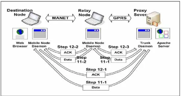
(30) Figure 4.1-3: the initialization protocol (3). 4.2 Data Transfer Protocol. The data transfer protocol deals with packet delivery and retransmission. In Figure 4.2, the trunk daemon sends data packets to the DN and its helping RNs through their GPRS channels in a round-robin sequence (step 11-1). When the RN receives a packet, it forwards the packet to the DN through the MANET (step 11-2). The DN then sends an acknowledgement packet to the RN (step 12-2). The RN then sends an acknowledgement packet to the trunk daemon to inform it that the DN has successfully received the packet (step 12-3). When the DN receives a packet that is sent directly from the trunk daemon to itself, it sends an acknowledgement packet directly to the trunk daemon to acknowledge the receipt of the packet (step 12-1).. - 20 -.
(31) Figure 4.2: The data transfer protocol.. The trunk daemon uses UDP to send packets to the DN and its helping RNs over their GPRS channels. RNs also use UDP to forward packets over the MANET to the DN. Since UDP does not provide a reliable service, the trunk daemon and mobile node daemons retransmit an encapsulated UDP packet in case it is lost on its way to its destination.. 4.2.1. Improvement of Acknowledgement. An acknowledgement packet to the trunk daemon may be loss in a GPRS network, so a DN or RN improves the acknowledgement scheme in case of acknowledgement packet loss. As any DN or RN sends an acknowledgement packet to the trunk daemon, it also informs the trunk daemon last acknowledgement packet that it sent.. Doing so, the trunk daemon can avoid needless retransmissions, when. an acknowledgement packet loses.. - 21 -.
(32) 4.2.2. Fast Retransmission in Our Scheme. To improve the performance of retransmission, the famous TCP fast retransmission mechanism is employed in our scheme to quickly detect and retransmit a lost packet.. The trunk daemon would retransmit the data packet when there is a data packet loss. Retransmission timeout time can not be too short, because round trip time of data packet in GPRS network is almost 3 seconds in the real world. Timeout time in our retransmission scheme should be shorter than timeout time in TCP protocol, or TCP congestion control would be triggered. Due to the reasons described above, the famous TCP fast retransmission mechanism is employed in our scheme.. When a data packet triggers the fast retransmission, the trunk daemon would dispatch this data packet to another mobile node different from the former mobile node. So, the trunk daemon can avoid dispatch the data packet to the mobile node whose GPRS link quality may be poor.. 4.2.3. Improved Fast Retransmission in Our Scheme. To further improve the performance of the fast retransmission in our scheme, a DN sends a selective data acknowledgement packet with some useful information in order to speed up a fast recovery. The fast retransmission sometimes can recovery - 22 -.
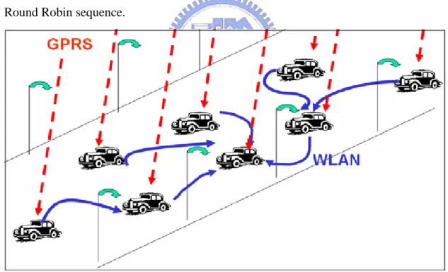
(33) data packet loss fast enough, when a bunch of data packets lose. So, a DN would enqueue a data packet in destination packet queue too long, when the trunk daemon has not triggered a fast recovery of this data packet. In our improved fast retransmission scheme, a DN would inform the trunk daemon that the DN enqueues some packets too long a time by sending a selective data acknowledgement packet with some useful information. So, the trunk daemon can do a fast recovery even when there have not been enough selective data acknowledgement to trigger a fast recovery.. 4.3 Ad-Hoc Routing Protocol. Our Ad-Hoc routing scheme can construct a routing table of any DN or RN, and support the mobility in MANET. Every DN or RN broadcasts a hello packet periodically, so it can construct its routing tables with zero hop count, called “Ad-Hoc Neighbor Table”. After constructing its Ad-Hoc Neighbor Table, every DN or RN exchanges its Ad-Hoc Neighbor Table periodically. Doing so, a DN or RN can know all reachable mobile nodes in MANET even the mobile node cross multiple hops. A DN or RN would set a timer for every routing entry. Therefore, a DN or RN would delete each routing entry periodically to prevent a routing entry from being out of time.. 4.3.1. Mobility Issues. To support the mobility in MANET, we improve our Ad-Hoc routing scheme to fast recover our system performance from mobile node topology changes. By this Ad-Hoc routing, our scheme can apply to a moving motorcade (Figure 4.3.1). An. - 23 -.
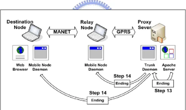
(34) important issue of the mobility in MANET is how to maintain the routing table correctly.. A simple description of our improved Ad-Hoc routing scheme is given below. In case of some RNs disconnect from DN, a DN checks the connectivity of every its RN in MANET periodically. Once a DN check out that it loses connectivity of a RN, this DN should delete the routing entry of this disconnected RN, and should inform every its RN about this disconnection. Therefore, a DN and every RN can refresh its routing table when the Ad-Hoc network topology changes. When a RN disconnects from DN, the trunk daemon will retransmit data packets in the RN’s sliding window (Figure 3.2.1-2), and dispatch those retransmitted data packets to other connected RNs in a Round Robin sequence.. Figure 4.3.1: a moving motorcade 4.4 Reset Protocol. The reset protocol is used to inform the DN and its helping RNs that the file download is completed. Figure 4.4 shows this protocol. When the apache server (PS) - 24 -.
(35) finishes sending the file content to the DN, it sends an “Ending” packet to the trunk daemon through a UDP socket (step 13) to notify it of this event. The trunk daemon in turns sends an “Ending” packet to each mobile node daemon involved in this file download (step 14). It then removes the firewall rules that were previously installed in the kernel and releases all the data structures and other resources allocated for this file download. When a mobile node daemon receives an “Ending” packet, it releases the used data structures and other resources. It also resets its state to prepare for another file download. If an “Ending” packet is lost, the mobile node daemon that should receive the packet will automatically release the used data structures and other resource after a certain period of channel idle time.. Figure 4.4: The reset protocol.. 5. EXPERIMENTAL SETTINGS AND RESULTS. - 25 -.
(36) 5.1 Experimental Settings. IBM A31 notebooks computer with 1.8G Hz CPU and 512 MB memory are used as PS and DN in our experiments.. Five notebooks tabled below are used as RNs.. Type. IBM A31. IBM R40. IBM T30. Toshiba. CPU. Intel 1.8G Hz. Intel 1.3GHz. Intel 2.2GHz. AMD 0.475GHz. Main Memory. 512 MB. 512MB. 512MB. 64MB. number. 1. 1. 1. 2. Each of RNs and each DN are equipped with an ASUS WL-14 IEEE 802.11(b) WLAN interface card or D-LINK DWL-122 and a Nokia D211 GPRS interface card, which is shown in Figure 5.1-2. In our scheme, every RN node is just responsible to forward data packets to DN. Therefore, using different machines listed above would not affect our system performance.. Because the two PCMCIA slots available on a notebook computer are too close to use one PCMCIA IEEE 802.11(b) and one PCMCIA GPRS cards at the same time, we used the ASUS WL-14 IEEE 802.11(b) interface card, which uses the USB interface rather than the PCMCIA interface to connect to the notebook computer. The Red-Hat Linux operating system with the 2.4 kernel is installed on each of these machines.. - 26 -.
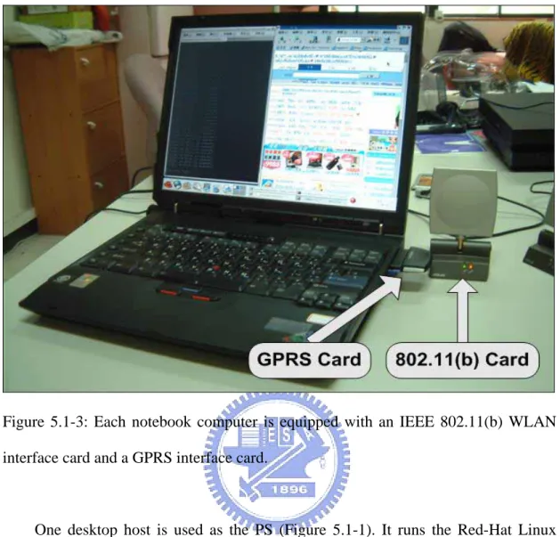
(37) Figure 5.1-1: The trunk daemon. Figure 5.1-2: Four notebook computers are used in experiments. One of them is used as the DN while the others are used as the DN’s helping RNs.. - 27 -.
(38) Figure 5.1-3: Each notebook computer is equipped with an IEEE 802.11(b) WLAN interface card and a GPRS interface card.. One desktop host is used as the PS (Figure 5.1-1). It runs the Red-Hat Linux operating system with the 2.4 kernel. This host is located in our laboratory and connected to the Internet. A modified apache web server is run on this desktop host to provide proxy services for the DN.. ChungHwa Telecom Inc. operates the GPRS network used in these experiments. When a GPRS network interface is attached to the GPRS network, ChungHwa Telecom Inc. automatically assigns a public IP address to it. As such, an Internet host (e.g., the PS) can actively send packets to an attached GPRS user.. We also try to evaluate our scheme on a different GPRS network, which is. - 28 -.
(39) operated by FarEastone Telecom Inc. On the FarEastone GPRS network, when a GPRS interface is attached to the network, it is assigned a private IP address. Normally, a machine assigned a private IP address is attached to a private network managed by a network address translator (NAT). Such a machine can actively exchange packets with a host on the Internet but a host on the Internet cannot actively exchange packets with it. This restriction, however, does not cause any problem for our scheme because before the PS sends packets to the DN, the DN and each of its RN have sent a “NAT Mapping Installation” packet to the PS.. However, the link quality of the GPRS network operated by FarEastone Telecom Inc is very unstable in the NCTU campus. Sometimes, our machines can hardly connect to the FarEastone GPRS network for five minutes. Due to the unstable link quality, the performance would be badly decreased. Therefore, we don’t evaluate our scheme on the FarEastone GPRS network.. 5.2 Experimental Results. 5.2.1 Calibration Test. In the calibration tests, we want to measure how the GPRS network performs when there are several CBR traffics activated simultaneously. In these tests, our scheme was not used. We measured the CBR throughput that can be achieved over one GPRS channel when one, two, three, and four GPRS channels are used simultaneously. The used channels were set up between the PS and the DN, and between the PS and the 3 RNs. Instead, on a tested GPRS channel, we pumped UDP packets at the PS machine into the channel at the constant bit rate. We used UDP - 29 -.
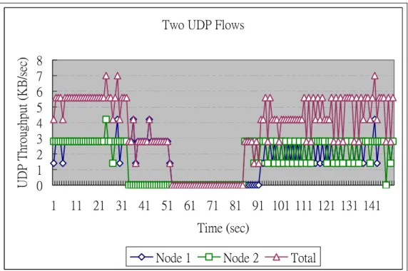
(40) packets rather than TCP packets because a TCP traffic source will reduce its sending rate at least by a half when encountering packet losses or reordering while a UDP traffic source will not. Since we are concerned with instantaneous link quality in a GPRS channel, we used UDP packets in the calibration tests.. In each CBR UDP packet stream, the packet interval time is 0.33 seconds and each UDP packet size is 1400 bytes. So, the maximum throughput of one CBR UDP packet stream is 4.2 Kbytes/sec. When UDP packets are sent at a constant bit rate over a GPRS channel, we say the channel is active. Figure 5.2.1-1 shows the throughput achieved on one channel when only one channel is active. Figure 5.2.1-2 shows the throughputs achieved on two channels when two channels are active at the same time. Figure 5.2.1-3 shows the throughputs achieved on three channels when three channels are active at the same time. Finally, Figure 5.2.1-4 shows the throughputs achieved on four channels when four channels are active at the same time. In these figures, we also show the total achieved throughputs of all active GPRS channels.. In Figure 5.2.1-1 below, the average throughput of a CBR UDP stream is close to 3 Kbytes/sec. In a CBR UDP packet stream, the packet interval time is 0.33 seconds and each UDP packet size is 1400 bytes. Therefore, we can only get four possible throughputs, 0 Kbytes/sec, 1.4 Kbytes/sec, 2.8 Kbytes/sec, 4.2 Kbytes/sec, in the calibration tests.. - 30 -.
(41) UDP Throughput (KB/sec). One UDP Flow 5 4 3 2 1 0 1 11 21 31 41 51 61 71 81 91 101 111 121 131 141 Time (sec) Node 1 Figure 5.2.1-1: The throughput of one GPRS channel.. UDP Throughput (KB/sec). Two UDP Flows 8 7 6 5 4 3 2 1 0 1. 11 21 31 41 51 61 71 81 91 101 111 121 131 141 Time (sec) Node 1. Node 2. Total. Figure 5.2.1-2: The throughputs of two GPRS channels.. From these figures, we have some observations. First, the maximum throughput that can be achieved over one GPRS channel is only about 4 KB/sec. Second, the quality of a GPRS channel is unstable. The throughput of a GPRS channel often drops to zero, stays at zero for a while, and then rises again. Third, when multiple GPRS - 31 -.
(42) channels are active, it is common that at least one channel’s throughput is very poor. These observations suggest that achieving N throughput speedup over N GPRS channels is almost impossible on current commercial GPRS networks. Three CBR UDP Flows UDP Throughput (KB/sec). 12 10 8 6 4 2 0 1. 10 19 28 37 46 55 64 73 82 91 100 109 118 127 136 145. Time (sec) Node 1. Node 2. Node 3. Total. Figure 5.2.1-3: The throughputs of three GPRS channels. Four UDP Flows UDP Throughput (KB/sec). 14 12 10 8 6 4 2 0 1. 10 19 28 37 46 55 64 73 82 91 100 109 118 127 136 145. Time (sec) Node 1. Node 2 - 32 -. Node 3. Node 4. Total.
(43) Figure 5.2.1-4: The throughputs of four GPRS channels.. Since the best aggregate UDP throughput achieved over N GPRS channels is much lower than N times of a GPRS channel’s native bandwidth (i.e., 36 Kbps), it is unreasonable to divide the throughput of our scheme by 36 Kbps to calculate its throughput speedup over N channels. In our web transfer throughput experiments, TCP (used by HTTP) is used to transport web files. Since TCP throughput suffers greatly from packet losses, reordering, large round-trip packet delays on the channel (3 ~ 4 seconds on a GPRS channel), and long channel blockage periods, our scheme faces a very challenging situation in which maintaining good TCP throughput over N unstable channels is difficult. It is nature that the aggregate TCP throughput achieved over N channels under our scheme is less than the aggregate UDP throughput achieved over N channels in the calibration tests.. Therefore, in the following subsection we will divide the TCP throughput of our scheme by the TCP throughput achieved over one channel (3.3 KB/sec) to calculate its speedup. This speedup represents the ratio of the performance of our N-channel scheme to the performance of a 1-channel scheme on the same commercial GPRS network. A high ratio value indicates that our scheme can better utilize the given N channels while a low value indicates that our scheme cannot.. 5.2.2 Evaluation Experiments. We measured the web download throughput of our scheme when one, two, three, and four GPRS channels are used. In each of these experiment suites, we measured the download throughput under different file sizes. For each file size, we repeated the - 33 -.
(44) experiment 10 times and report their average and standard deviation. In the experiments, the web server hosting these files resides on the same subnet as the PS.. In the first experiment suite, no RN provides additional GPRS channel bandwidth to help the DN download its requested file. Thus, the packets carrying the file’s content are transmitted on the DN’s own GRPS channel. Figure 5.2.2-1 shows that the average throughput without applying out scheme is about 3.3 KB/sec when the file size is greater than 50 KB. For each average throughput data point, the point above it is the average plus the standard deviation and the point below it is the average minus the standard deviation.. TCP Throughput (KB/sec). No Relay Node 4 3.5 3 2.5 2 1.5 1 0.5 0 0. 100. 200. 300. 400. 500. 600. File Size (KB) Avg. (Avg + Std Dev). (Avg - Std Dev). Figure 5.2.2-1: The average file download throughput with different sizes (through only one GPRS channel).. In the second experiment suite, one RN is used and its channel and the DN’s channel are used to download the file in parallel. Figure 5.2.2-2 shows that the - 34 -.
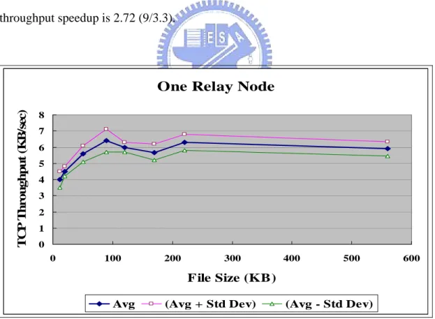
(45) average throughput is about 6 KB/sec when the file size exceeds 90 KB. The throughput speedup is 1.82 (6/3.3).. In the third experiment suite, two RNs are used and in total three GPRS channels are used to download the file in parallel. Figure 5.2.2-3 shows that the average throughput is about 8 KB/sec when the file size exceeds 560 KB. The throughput speedup is 2.42 (8/3.3).. In the fourth experiment suite, three RNs are used and in total four GPRS channels are used to download the requested file in parallel. Figure 5.2.2-4 shows that the average throughput is about 9 KB/sec when the file size exceeds 550 KB. The throughput speedup is 2.72 (9/3.3).. TCP Throughput (KB/sec). One Relay Node 8 7 6 5 4 3 2 1 0 0. 100. 200. 300. 400. 500. 600. File Size (KB) Avg. (Avg + Std Dev). (Avg - Std Dev). Figure 5.2.2-2: The average file download throughput with different sizes (through two GPRS channels).. - 35 -.
(46) TCP Throughput (KB/sec). Two Relay Nodes 10 9 8 7 6 5 4 3 2 1 0 0. 100. 200. 300. 400. 500. 600. File Size (KB) Avg. (Avg + Std Dev). (Avg - Std Dev). Figure 5.2.2-3: The average file download throughput with different sizes (through three GPRS channels).. TCP Throughput (KB/sec). Three Relay Nodes 12 10 8 6 4 2 0 0. 100. 200. 300. 400. 500. 600. File Size (KB) Avg. (Avg + Std Dev). (Avg - Std Dev). Figure 5.2.2-4: The average file download throughput with different sizes (through - 36 -.
(47) four GPRS channels).. From Figure 5.2.2-1 to Figure 5.2.2-4, we see that the average file download throughput is low, when the file size is small. This phenomenon can be explained as follows. After a TCP connection is set up, it immediately enters the TCP slow-start congestion control phase. In this phase, the TCP sender exponentially increases its sending rate (its congestion window size ---- the number of unacknowledged packets that can be sent out per RTT) in each subsequent RTT, where RTT is the round trip time between the TCP sender and receiver. For example, a TCP sender sends out 1, 2, 4, 8, and 16 packets in the 1st, 2nd, 3rd, 4th, and 5th RTT respectively, If the size of the requested file is small and thus only few packets need to carry its content, finishing the file transfer will use only the first few RTTs. Since a TCP sender’s sending rate is its congestion window size divided by its RTT and the GPRS channel’s RTT is very large (3 ~ 4 seconds for a standard-sized 1500-byte packet), the TCP sender’s sending rates in the first few RTTs are the lowest. As such, TCP throughputs on GPRS channels are low for small files regardless whether our scheme is used or not.. To further evaluate our scheme, we measured the web download throughput when five GPRS channels are used. In that experiment suite, because we only have four GPRS accounts of ChungHwa Telecom Inc, we used three RN operated on the ChungHwa GPRS network, and one RN operated on FarEastone GPRS network. So, in total five GPRS channels are used to download the requested file in parallel. However, this experiment didn’t perform well, and the throughput even is lower than 5 Kbytes/sec (twice the TCP GPRS throughput without using our scheme) sometimes. The unstable link quality on FarEastone GPRS network in the NCTU campus did decrease the performance, and more data packets would be out of order in this - 37 -.
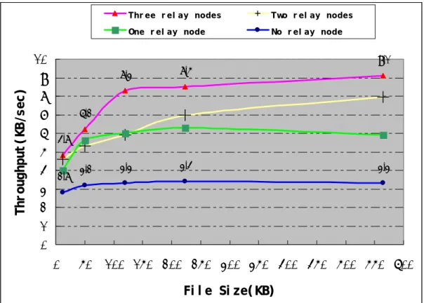
(48) experiment. Therefore, adding one more channel doesn’t necessary increase the performance of our scheme depending on the signal strength of the new GPRS channel. Figure 5.2.2-5 is the conclusion from Figure 5.2.2-1 to Figure 5.2.2-4. Readers can also reference Figure A-1 in the Appendix.. Figure 5.2.2-6 (Figure A-2) shows the speedup rate when we used different number of RNs in our experiments. Our scheme can get triple times of TCP GPRS throughput when there are three RNs forwarding data packets.. Thr ee r el ay nodes. Two r el ay nodes. One r el ay node. No r el ay node. Thr oughput ( KB/sec). 10. 9.1. 9 8 6.2 7 6 4.8 5 4 2.8 3.2. 8.3. 8.5. 3.3. 3.4. 3.3. 3 2 1 0 0. 50. 100 150 200 250 300 350 400 450 500 550 600 Fi l e Si ze( KB). Figure 5.2.2-5: experiment results in the real world. - 38 -.
(49) Speedup Rat e. 3. Thr ee r el ay nodes. Two r el ay nodes. One r el ay node 2.7 2.5. No r el ay node. 2.5 2 1.5. 2.91. 2.4 1.9 1.71 1.75 1.6 1.69 1.42. 2.2 1.93 1.81. 1.85. 1.68. 1 0.5 0 0. 50 100 150 200 250 300 350 400 450 500 550 600 Fi l e Si ze ( KB) Figure 5.2.2-6: experiment speedup in the real world. The results shown in these figures and the above explanation suggest that our scheme is more suitable for downloading large files than downloading small files. Actually, when the download file size is small, there is no need to use our scheme to further reduce the small transfer time.. 6. SIMULATION SETTINGS AND RESULTS In the simulation experiments, we evaluated our scheme about some issues such as system performance when number of RNs increases and mobility support in MANET.. - 39 -.
(50) 6.1 Simulation Settings and Modifications. To run our applications such as the trunk daemon and the mobile node daemon on NCTUns2.0, some settings and modifications should be done. On NCTUns2.0, modified kernel uses Source-Destination-Pair IP address scheme to route packets from applications. But by using the fully-integrated GUI environment, a user need not know the concept and need not use the source-destination-pair address scheme at all. However, when users try to use RAW socket, and install firewall rules to divert packets from IP queue, their application should be modified to work well under the Source-Destination-Pair IP address scheme of NCTUns2.0. So, due to the Source-Destination-Pair IP address scheme on NCTUns2.0, we do some modifications in our trunk daemon and mobile node daemon.. We focus on some issues such as system performance when number of RNs increases and mobility support in MANET when doing the simulation experiments. Therefore, we used our modified traffic generators to take place the modified apache server in our scheme. Then, we can evaluate our scheme by one TCP connection or a CBR UDP packet stream. We also can evaluate the performance of our routing scheme which is hard to be evaluated in the real world.. 6.2 Simulations Results. 6.2.1. Calibration Tests for the GPRS package on NCTUns2.0. In those calibration tests, we want to evaluate the GPRS system performs on NCTUns2.0 without using our scheme. - 40 -.
(51) In Figure 6.2.1-1, there is a topology of common GPRS network on NCTUns2.0. Node 1 is the Base Station, and the Base station connects to a host (Node 5) in the Internet. Node 7 is a cellular phone. Node 6 is the mobile computer equipped with a GPRS network card and an 802.11b wireless card.. Figure 6.2.1-1: simple topology of GPRS network. Figure 6.2.1-2 shows the protocol stack of a GPRS Base Station. Each RLC module has its own transmission queue with a limited number of slots. A packet is allowed to enter an RLC module if the transmission queue in that RLC module has enough slots to store that packet. Otherwise, the packet will be put back into the GPRS FIFO module until the RLC module has enough space for storing this incoming packet.. - 41 -.
(52) Figure 6.2.1-2: the protocol stacks of base station. We present the GPRS TCP throughput in Figure 6.2.1-3 (Figure A-3) without using our scheme. The pink line represents the current queue size of GPRS FIFO, and the blue line represents the TCP throughput.. The GPRS FIFO is overflow between 36 seconds to 55 seconds, so GPRS base station would drop some data packets during that period. This condition would trigger the congestion control of a TCP connection, so the TCP throughput drops to zero between 61 seconds to 78 seconds. The size of current GPRS FIFO decreases after 58 seconds, therefore slow start of the TCP connection can progress. After a while, the GPRS TCP throughput climbs up again.. We present the GPRS UDP throughput in Figure 6.2.1-4 (Figure A-4) without using our scheme. We pump a CBR UDP packet stream about 3.75 Kbytes/sec on PS. - 42 -.
數據
+7
相關文件
• The stimulation of domestic demand aims to changes the Chinese economy from the one aimed at encouraging investments to one where demand and domestic consumption plays a
The remaining positions contain //the rest of the original array elements //the rest of the original array elements.
Generic methods allow type parameters to be used to express dependencies among the types of one or more arguments to a method and/or its return type.. If there isn’t such a
contributions to the nearby pixels and writes the final floating point image to a file on disk the final floating-point image to a file on disk. • Tone mapping operations can be
Experiment a little with the Hello program. It will say that it has no clue what you mean by ouch. The exact wording of the error message is dependent on the compiler, but it might
The client’s web browser sends a request to the server for a web page that runs a Java servlet.
When renaming a file without changing file systems, the actual contents of the file need not be movedall that needs to be done is to add a new directory entry that points to
According to the problem statement and literature reviews, several functionalities are identified for the proposed CBI-PSP, including: (1) a knowledge classifications scheme
