Yuan Mao Huang
Professor, Department of Mechanical Engineering, National Taiwan University,Taiwan
Study of Unsteady Flow in a Heat
Exchanger by the Method of
Characteristics
The one-dimensional, unsteady flow in an air-to-air heat exchanger is studied. The governing equations are derived and the method of characteristics with the uniform interval scheme is used in the analysis. The effect of the fin improvement factor on the air temperature in the heat exchanger and the heat transfer rate of the heat exchanger, and air properties in the heat exchanger are analyzed. The numerical results are compared and show good agreement with the available data.
Introduction
Heat exchangers are used in HVAC systems and many ap-plications. Improper design of a heat exchanger may result in the damage or degradation of the components and the per-formance of a system. Kraus (1988) dealed with the mathe-matical representation of individual fins. Rindt et al. (1991) presented a numerical model for an unsteady entrance flow in a 90-deg curved tube. Bulck (1991) determined the optimal distribution of the transfer surface area for the maximum heat exchanger effectiveness and the constant total surface area.
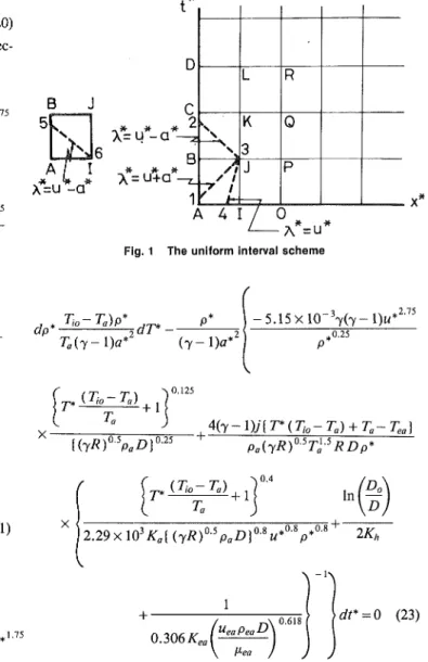
The effects of the unsteady fluid properties are important because the heat transfer rate and the performance of a heat exchanger depend on these properties. The unsteady flow in an air-to-air heat exchanger is complicated. The air flow in the heat exchanger is assumed one-dimensional and unsteady in this study. The method of characteristics (Abbott, 1970) is used to simplify the governing equations into nonhomogeneous first-order partial differential equations. The uniform interval scheme (Soo, 1969) is applied to analyze the effect of the fin improvement factor on the air mean temperature in the heat exchanger and the mean heat transfer rate of the heat ex-changer, and air properties in the heat exchanger. The nu-merical results for specific operating conditions are compared with the available data.
Method of Approach
The air-to-air heat exchanger of interest is assumed to be a straight tube with the constant circular cross-sectional area surrounded by fins. The air flow in the heat exchanger is assumed unsteady and one-dimensional. The continuity equa-tion is
dp dp du ^r+u-— + p—- = 0
dt dx dx (1)
Contributed by the Pressure Vessels and Piping Division for publication in
the JOURNAL OF PRESSURE VESSEL TECHNOLOGY. Manuscript received by the PVP
Division, August 3, 1990; revised manuscript received April 23, 1992. Associate Technical Editor: F. J. Moody.
It is assumed that air is an ideal gas. Thus,
p = PRT (2)
Neglecting the body force for the low-density air in a horizontal heat exchanger, the momentum equation is
du du nrr,dp „dT f , «
dt dx dx dx 2Dr
(3) For Reynolds number, Re, based on the inside diameter of the tube up to 105, an empirical formula of the friction factor, / , in a smooth tube suggested by Blasius is (Kreith, 1965)
/ = 0 . 3 1 6 R e " (4) In the temperature range of interest, the specific heat at con-stant volume, C„, is nearly concon-stant and the viscosity given by Kays and London (1962) is
/ n = 1 1 3 . 2 x l 0 "8r ° (5) Since the Biot number is smaller than 0.1 for the present case and the wall of the heat exchanger is thin, the heat ab-sorbed by the wall is negligible (Kreith, 1965). However, the temperature drop across the wall must be considered. For a fully developed flow in a smooth tube with Reynolds number in the range of 104 to 1.2 x 10⁵ and Prandtl number near to one, Dittus and Boelter (Holman, 1972) recommended
h„ = 0 . 0 4 ^ Re0 (6)
The ambient air with the constant temperature and velocity is blown continuously over the heat exchanger by a fan. The average convective heat transfer coefficient of air with Re in the range between 4 x 10³ and 4 x 10⁴ is
/z„, = 0.306--Ke, (7)
Hence, the heat transfer rate per unit area is
T— T
* * en (8) In
D 1
the continuity equation, the m o m e n t u m equation and the en-ergy equation in nondimensional form are
i + -
-+;
1
dp* dp* du*
(14) , 0 . 0 4 / ^ R e0-8 lKh 0.306A:eaRe°a618
Neglecting the change of the air potential energy, the energy equation is „ dT „ dT RTdu Cv—-+Cvur-- +
1 (
TAT
i0-T
a)W tH
7[ Ta )bx* p dt* dt dx j dx SASxlQ-^/upD" Dj \T°-,4(T-T„) u +• In pD Do D'2.29xl0
3/r
flfe
1
2K
h + 0.306#e, The rate of heat transfer isUeaPegD P*ea
Q=\,
•wDdx dimensional variables are defined asP*=^ Pa
(T-
(71,-D
.
u u*= — aa * x Ta) -Ta)~>
J
>
= 0 (9) (10) (11)The speed of sound, aa, is evaluated at atmospheric con
ditions. Using Eq. (11) and the relations of Oa = yRTa and R , , Ju* (Ti0-Ta)p* dT* dx* 7 Ta dx*
5J5xio-y
0V'-
75r * ^ V ^
+i
((7 jR)0-5 P f lD!0-2 5 = 0 (15) and (Ti0-Ta)dT* , (Ti0-T0) JT* Ta dt* Ta dx*+ (T
_
1)|7
.<2t5>
+ 1
]£
5.15 X 1 0 -3 7(7- 1)) T* {TioZ Ta) + l ] u*115+ 4(
7-l)yX
(7JR)°-5P0D1°-25P*0.25 T*(Ti0-Ta) + Ta-Tea Pa(yR)°-5T0-5RDp* J* ( TjQ T„) ^>S
| 2.29 X 1 03i U (7i?)%aZ3)0-8«*°-8p*°-8 + 2Kh 1 0.306/C, UeaPeaD 0.618 | = 0 (16)The method of characteristics is used with nondimensional characteristics as dx* ' dt* (17) ( 7 - 1 ) / (12) (13)
The nondimensional characteristic directions determined from the determinant of Eqs. (14), (15), and (16) are
\* = u* + a* (18) \* = u*-a* (19)
N o m e n c l a t u r e
a = sonic speed, m / s
C„ = specific heat at constant vol-ume, J/kg-K
D = inside diameter of heat exchan-ger, m
D0 = outside diameter of heat
ex-changer, m / = friction coefficient
j = heat and work conversion fac-tor, N - m / J
h = heat transfer coefficient, J / s -m2-K
K = thermal conductivity
p = pressure, N / m Q = heat transfer rate, J / s
q = heat transfer rate per unit area, J/s-m2 R = gas constant, N-m/kg-K Re = Reynolds n o . T = temperature, K t = time, s u = velocity, m / s
x = distance from heat exchanger inlet, m
7 = ratio of specific heats X = characteristic direction
ix = viscosity, kg/m-s p = density, k g / m3
Subscripts
a = ambient condition or air ea = condition surrounding heat
ex-changer
h = condition of heat exchanger io = initial condition at heat
exchan-ger inlet
Superscripts
and
X* = w* (20)
The compatability equations along the characteristic direc-tions, Eqs. (18), (19), and (20), respectively, are
J * , yP* j . , (Ti0-T„) p* I . . . 3 0.75 ,1.75 dp*+ —-du*+ — 2^T + < 5.15 X 10 yp* u* a Ta a* p* ) - 5 . 1 5 x l 0 -37 ( Y - l ) " *2'7 5 a*i(yR)°-ipaD)0-25 T a*2] X*=u*a* X*=u*-a*-* X*=u*-a*-* X*=u*-a*-* X = u + a -B
1
A 4 I / 0
• i 0 A*=u*Fig. 1 The uniform interval scheme
™ \Jjo_J_a}_ . l(yR)0-5paD}°-2s 4(y-l)J{T*(Th-Ta) + Ta-Tea) dp PaiyRV'T^RDp * 'JO Tg)p _frpjlc Ta(y-\)a* dT*-- • 5 . 1 5 x l 0 ~37 ( T - l ) " *2'7 5 ( 7 - l ) « * - + 1 In D I2.29X 103Ka{ (yR)0-5paD)Mu*°-V0-1 2Kh
f* *• '" "' i i 0.5 „ r>)0.25 \{yR)^PaD 4(y-l)j{T*(Ti0-Ta) + Ta-Tea Pa(yRf5Ta-5RDp* 1 0.306 A;, ueapeaD >dt* = 0 (21) T* — + 1 In D, Ta ) \D
\2.29xl03Ka{(yR)0-5PaD}0-Su*0,ip*OS+ 2K»
dp
*_yjl
du*
+^zIA£L
dr+\_
5A5^^
1P^
u^
a* Ta a* 1 0.306JC, ueapmD \dt*=0 (23) rp, \ ' io *a) . a*{{yR)°-5paD}0-25
These equations which are nonlinear ordinary differential equations can be solved by the finite difference method. Only the terms of the first-order in Taylor series expansion are used. 2 75 The uniform interval method is used by dividing the plane with p* ) - 5 . 1 5 x 1 0 y(y-l)u* coordinates x* and t* into several uniform interval areas as p*°'2s shown in Fig. 1. Each net point stands for a specified location
of x* and time of /*. (Tio-Ta) + 1 (yR)0SpaD}°-25 4(7 -l)J{T*(Tio-Ta) + Ta-Te pa(yR)°-5T^RDp* rp, \*io J a) . Ta \2.29xl03Ka{{yR)°-5paD} 1 j , 0 . 8 ,.0.* U* p * 2Kh 0.306 JC, Mea Pea ^ P<ea and Results
The thermal conductivities of air and the heat exchanger used for analysis are 0.0099 J/s-m-K and 117.49 J/s-m-K, respectively. The inside diameter, the wall thickness and the length of the heat exchanger are 19.1 mm, 1.55 mm and 7.62 m, respectively. The available existing periodic data of air properties at the heat exchanger inlet are used as the boundary condition, and the fluctuating amplitudes of the velocity, pres-sure, temperature and density of the air used are 129, 10, 3 and 7 percent of the respective mean values of 49 m / s , 273 KPa, 383 K and 2.55 Kg/m3, respectively. The period is equal to 0.003 s which is divided into five sections: 0.0000, 0.0006, 0.0012, 0.0018 and 0.0024 s. These five sections with uniform intervals are used to describe air properties along the heat dt* = 0 (22) exchanger.
An assumed initial temperature distribution along the heat exchanger is required. For comparison with the existing data, it is assumed that the maximum temperature at the heat ex-changer inlet is linearly decreased to the ambient temperature
at the one-third of heat exchanger length and then remained constant at the ambient temperature for the remainder of the heat exchanger. The final results for air properties in the heat exchanger are independent of the assumed initial temperature
335
2 3 A 5 6 LENGTH OF HEAT EXCHANGER ( m )
Fig. 2 The effect of the fin improvement factor on the air mean tem-perature along the heat exchanger
distribution. However, a good assumption can reduce com-puter time substantially.
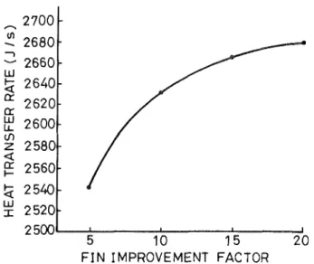
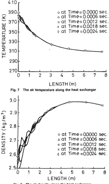
The fin improvement factor, n, is used to multiply the con-ductivity of air surrounding the heat exchanger for the Hilpert average heat transfer coefficient. The effect of the fin im-provement factor from 5 to 20 on the air mean temperature along the heat exchanger up to 7.62 m long is shown in Fig. 2. The effect of the fin improvement factor on the mean heat transfer rate out of the heat exchanger is shown in Fig. 3. The mean heat transfer rate out of the heat exchanger with the fin improvement factor equal to 10 is integrated along its length as shown in Fig. 4. The results of the velocity, pressure, tem-perature and density of the air along the heat exchanger at 0.0000, 0.0006, 0.0012, 0.0018, and 0.0024 s with the fin im-provement factor equal to 10 are shown in Figs. 5 through 8.
Discussion
A good choice of certain combinations of the variables can make the derivation of equations easily (Lin, 1950). The sonic speed and the heat transfer rate are functions of temperature. Therefore, temperature is chosen as one variable. Density which proves convenient during the derivation of the governing equa-tions is chosen as another variable. The chosen time interval
UJ cc a: Ul
u.
to<
cr<
LUI
2700
2680
2660
2640
2620
2600
2580
2560
2540
2520
2500
5 10 15
FIN IMPROVEMENT FACTOR
20
0
oat Time=0.0000 sec.
* a t Time =0.0006 sec.
• at Time=0.0012sec.
xat Time= 0.0018 sec.
oat Time = 0.0024 sec.
Fig. 3 The effect of the fin improvement factor on the mean heat trans-fer rate of the heat exchanger
1 2 3 4 5
LENGTH (m)
Fig. 5 The air velocity along the heat exchanger
UJ
g 1500
8
3 4 5 6 5
LENGTH(m)
Fig. 4 The mean heat transfer rate out of the heat exchanger versus the length of the heat exchanger
oat Time=0.0000 sec.
A at Time=0.0006sec.
• at Time=0.0012 sec.
x a t Time=Q0018 sec.
o at Time = 0.0024 sec.
0 1 2 3 4 5 6 7
LENGTH(m)
4 1 0 ,
390
o a t Time = 0.0000 sec.
A at Time=0.0006 sec.
• at Tim e= 0.0012 sec.
x at Time = 0.0018 sec.
o at Time =0.0024 sec.
0 1
LENGTH (m)
Fig. 7 The air temperature along the heat exchanger
o at Time = 0.0000 sec.
A at Time =0.0006 sec.
a at Time = 0.0012 sec.
x at Time =0.0018 sec.
o at Time =0.0024 sec.
1 2 3 4 5
LENGTH (m)
Fig. 8 The air density along the heat exchanger8
must be small enough to give accurate results and yet it should
be large enough to minimize computer time.
The available air temperature at the heat exchanger inlet is
about 378 K to 388 K. The larger the fin improvement factor,
the faster the temperature decreased along the heat exchanger.
A value of the fin improvement factor larger than 10 does not
provide much better performance. Therefore, the fin
improve-ment factor of 10 is used. The calculated air temperature at
the heat exchanger outlet is 307 K, which is comparable with
304.4 K to 305.5 K measured by Edwards and McDonald
(1972).
Comparing the mean heat transfer rates obtained by
inte-grating the heat transfer out of the heat exchanger, 2630 J/s,
and by the difference of the air mean enthalpy between the
inlet and the outlet of the heat exchanger, 2615 J/s, shows
that the analytical tool provides good result. The choice of 50
intervals of x for 7.62 m long and 5 intervals of / for a period
of 0.003 s provides satisfactory results. The analytical tool can
also be used for analyzing other operating conditions.
References
Abbott, M. B., 1970, An Introduction to the Method of Characteristics, American Elsevier, New York.
Bulck, E. Van den, 1991, "Optimal Design of Crossflow Heat Exchangers," ASME Journal of Heat Transfer, Vol. 113, pp. 341-347.
Edwards, T. C , and McDonald, A. T., 1972, "ROVACS: A New Rotary-Vane Air-Cycle Air-Conditioning and Refrigeration System," SAE Paper No. 720079.
Holman, J. P., 1972, Heat Transfer, 3rd Edition, McGraw-Hill, New York, Chap. 6, pp. 158-161, 182-191.
Kays, W. M., and London, A. L., 1962, Compact Heal Exchanagers, McGraw-Hill, New York.
Kraus, A. D., 1988, "Analysis of Extended Surface," ASME Journal of Heat Transfer, Vol. 110, Nov., pp. 1071-1081.
Kreith, F., 1965, Principles of Heat Transfer, 2nd Edition, Scranton, Inter-national, Pa., Chaps. 8 and 9.
Lin, C. C , 1950, "Note on the Characteristics in Unsteady One-Dimensional Flow with Heat Addition," Quarterly of Applied Mathematics, Vol. 7, pp. 443-445.
Rindt, C. C. M., Steenhoven, A. A. van, Janssen, J. D., and Vossers, G., 1991, "Unsteady Entrance Flow in a 90 deg Curved Tube," Journal of Fluid Mechanics, Vol. 226, pp. 445-474.
Soo, S. L., 1969, "Uniform End Interval Method for Computing One Di-mensional Transient Flow," SAE Paper No. 690465.