Planning of sluicing tunnel in front of the
Wushe dam - retrofit the existing water
diversion tunnel as an example
Chang-Ting Hsieh, Sheng-Yung Hsu, Chin-Pin Ko
Abstract
This study on retrofit of water diversion tunnel to remove silt and sediments, reach for the relationship between the elevation of intake and the sediment removal efficiency with the FLOW-3D simulation software. In addition, since the maximum head difference of the sluicing tunnel is about 110 meters, it needs to be dissipated in the space of about 300 meters and then discharged into the downstream river. The layout of the tunnel streamline alignment has the limitation of using the existing water-diversion tunnel, unlike the general sluicing tunnel with straight streamline. The path of the sluicing tunnel will adopt a straight-line steep groove, and the bottom will be connected with the existing water diversion tunnel by a curve path. It is very important to discuss the energy dissipation arrangement of high-speed water flow in the tunnel. Research the energy dissipation arrangements, and then analyze and compare according to the FLOW-3D simulation software, and finally recommend the best energy dissipation. Keywords: Sluicing tunnel, High-speed water flow, Energy dissipation arrangement
1 Introduction
The Wushe reservoir was completed in 1959, which initial storage capacity was 150 million cubic meters. In 2008, a large amount of sediment was deposited in the sinlaku typhoon ,which reduced the storage capacity of the wushe reservoir. The reservoir has been in operation for about 60 years, the storage capacity as of 2016 was 43.7 million cubic meters - a deposition rate of 70.9 percent. The sediment buildup has significantly affected power generation, irrigation, flood control, water availability, and tourism. In November 2016, sediment elevation behind the dam and the water intake was EL. 975 meters, while the bottom of generator 1 and 2 water intake was EL. 938.5, a difference of 36.5 meters. Normal water intake and power generation will be affected by the silt and other sediments deposited. Therefore, it is necessary to study the planning of sluicing tunnel in front of the dam.
2 Content
The existing water diversion tunnel in the wushe reservoir, which length about 300 meters, the cross section is 3.2 m in width and 6 m in high. During the construction of the dam(1937~1944), it was used to discharge the natural flow of Wushe river. In 1957,
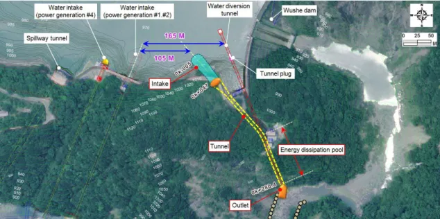
the water diversion tunnel was blocked and reservoir was completed. The water diversion tunnel was located 165 meters downstream side of the power water intake (generator #1 and #2) ,which immediately adjacent to the Wushe dam. Consider construction feasibility and dam safety, the location of the sluicing intake must be kept at a safe distance. Therefore, the intake of sluicing tunnel was arranged 105 meters downstream side of the power water intake (see Figure 1).
According to the latest hydrological analysis results (annual maximum flood data statistical: 1959-2016), which the flood discharge for 2-years return period is 531 cms. However, the latest reservoir safety assessment result show that when the maximum possible flood (PMF) occurs, the reservoir will have insufficient flood discharge capacity, which has the risk of flood discharge and the need to increase flood discharge capacity. Therefore, the design flood-discharging capability of the sluicing tunnel is recommended to be 530 cms. The reservoir bed sediment survey result in 2009, which silt sand in front of the water intake for power generation belongs to fine mud (D50=0.015mm). The sediment sluicing object should be set to fine-grained mud to
reduce the siltation elevation in front of the water intake.
Figure 1: Sluicing tunnel planning location of Wushe reservoir
The major objectives arise from the sluicing tunnel :
A. Enhance the desilting capability and decrease sediment (silt with a particle size of less than 0.02 mm) in front of the reservoir. According to the demand for power generation, it is proposed to use high water level flood detention and sediment evacuation operation.
B. Enhance the flood-discharging capability of the reservoir to ensure the safety while extreme hydrological events happened.
3 Layout of sluicing tunnel
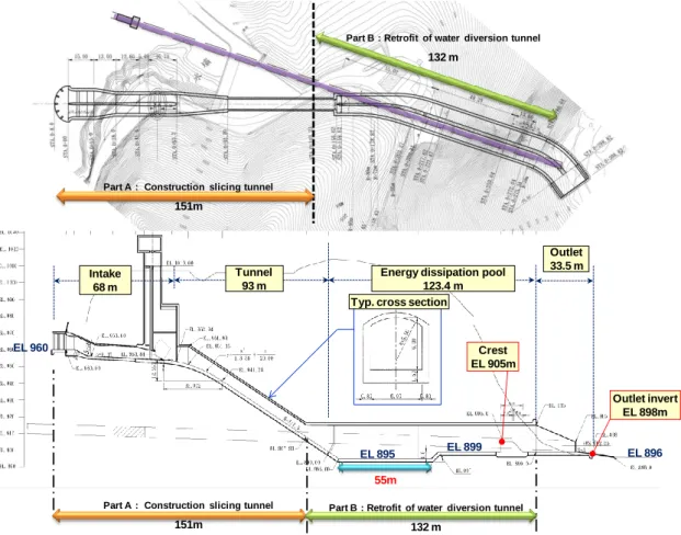
The sluicing tunnel consists of the intake structure, tunnel, outlet structure, and energy dissipation pool. The length of the intake structure is 68 m and is situated at right bank area of the dam. The length of the tunnel is 93 m with a slope 66.67%, which the typical cross section is 6 m in width and 6 m in height (see Figure 2). For the aim to retrofit of water diversion tunnel to remove sediment sand the requirement at maintenance stage, an dissipation pool is designed for 123.4 m in length. In order to energy dissipation well, the pool divide two channels, which section is 7 m in width and 16 m in height. And the front section of the energy dissipation pool is set with a water cushion depth of 4 meters and a length of 55 meters. Set the subsidiary dam in the back section of the energy dissipation pool, the height is 6 m.
Figure 2: Plan view and profile of the sediment sluicing tunnel at Wushe reservoir
4 Hydraulic analysis with FLOW-3D model
At high water level (EL. 1,005 m) operation, the flow velocity in the steep groove tunnel from 20 m/s to 40 m/s. The maximum water depth was about 4 m, which has freeboard was 33%. The maximum velocity occurs at the separation wall at the beginning of the energy dissipation pool (see Figure 3). The turbulence flow just occurs in the left side tunnel wall of energy dissipation pool, estimated the impact of uneven
Outlet invert EL 898m
Part B : Retrofit of water diversion tunnel
132 m
Part A : Construction slicing tunnel
151m 55m EL 896 EL 895 Crest EL 905m EL 899 Intake 68 m Tunnel 93 m
Energy dissipation pool 123.4 m
Outlet 33.5 m
Typ. cross section
Part A : Construction slicing tunnel
151m
Part B : Retrofit of water diversion tunnel
132 m
flow rate development after water diversion point. Overall, the flow condition of the energy-dissipation pool has developed into a stable flow condition, indicating that this plan has a good energy-dissipating effect (see Figure 4). The final flow velocity from outlet to the river channel is 12 m/s.
Figure 3: The flow velocity distribution in the steep groove tunnel
Figure 4: The flow velocity and water level situation in the energy dissipation pool
Design discharge: 530cms ;Freeboard : 33% ; Maximum velocity: 40m/s
Flow velocity distribution in energy dissipation pool
Stable flow condition
Turbulence occurs in left side
Crest : water level EL 911.8m
5 Conclusions
In this case study shown retrofit of water diversion tunnel to be a new sluicing tunnel was difficult and with many limitation factor. Due to the the demand for power generation, which use high water level flood detention and sediment evacuation operation. The rate of siltation rise in front of the water intake for power generation is reduced to 72%~78% of the current situation. When there is no sand evacuation facility in the reservoir, the more difficulties it will encounter if the sluicing tunnel is set up later.
References
Taiwan Power Company (2018). Improvement of sediment management for the generator 1 and 2 water intake at Wanda Power Plant — Feasibility study on retrofit of water diversion tunnel to remove sediment.
Henry, T. Falvey (1990). Cavitation in Chutes and Spillways, U.S. Department of the Interior, Bureau of Reclamation (USBR).
Ellis, J. (1989). Guide to Analysis of Open-channel Spillway Flow, Technical note 134, Construction Industry Research and Information Association (CIRIA), London, 1989.
Peterka, A. J. (1984). Hydraulic Design of Stilling Basins and Energy Dissipators, U.S. Department of the Interior, Bureau of Reclamation (USBR), Denver, 8th ed. 1984.
Authors
Chang-Ting Hsieh (corresponding Author) Sheng-Yung Hsu
Chin-Pin Ko
Sinotech Engineering Consultants, LTD. (Taiwan, R.O.C) Email: hct72@mail.sinotech.com.tw