Switchable viewing angle display with a compact
directional backlight and striped diffuser
Yi-Jun Wang,1 Jian-Gang Lu,1,* Wei-Chung Chao,2 and Han-Ping D. Shieh1,2 1National Engineering Lab for TFT-LCD Materials and Technologies, Department of Electronic Engineering,
Shanghai Jiao Tong University, Shanghai, 200240, China
2Dept. of Photonics & Display Institute, National Chiao Tung University, Hsinchu, 300, Taiwan *lujg@sjtu.edu.cn
Abstract: A compact high-directionality backlight module combined with a
striped diffuser is proposed to achieve an adjustable viewing angle for eco-display. The micro-prisms on the compact light guide plate guide the emitting rays to the normal viewing angle, whereas a set of striped diffusers scatter the rays to a wide viewing angle. View cones of ± 10° / ± 55° were obtained for narrow/wide viewing modes with 88% / 85% uniformity of spatial luminance, respectively. Compared with the conventional backlight, the optical efficiencies were increased by factors of 1.47 and 1.38 in narrow and wide viewing modes, respectively. In addition, only 5% of power consumption was needed when the backlight worked in private narrow viewing mode to maintain the same luminance as that of a conventional backlight.
©2015 Optical Society of America
OCIS codes: (080.2740) Geometric optical design; (230.3990) Micro-optical devices;
(230.4000) Microstructure fabrication; (220.4830) Systems design.
References and links
1. Y. Hisatake, Y. Kawata, and A. Murayama, “Viewing angle controllable LCD using variable optical compensator and variable diffuser, ” SID Symp. Digest 36(1), 1218–1221 (2005).
2. M. Adachi, “Controllable-viewing-angle display using a hybrid aligned nematic liquid-crystal cell,” Jpn. J. Appl. Phys. 47(10), 7920–7925 (2008).
3. Y. J. Lim, E. Jeong, M. H. Chin, S. Ji, G. D. Lee, and S. H. Lee, “Viewing angle switching of patterned vertical alignment liquid crystal display,” J. Phys. D Appl. Phys. 41(8), 085110 (2008).
4. M. S. Kim, Y. J. Lim, S. Yoon, S. W. Kang, S. H. Lee, M. Kim, and S. T. Wu, “A controllable viewing angle LCD with an optically isotropic liquid crystal,” J. Phys. D Appl. Phys. 43(14), 145502 (2010).
5. K. W. Chien, Y. J. Hsu, and H. M. Chen, “Dual light source for backlight systems for smart viewing adjustable LCDs, ” SID Symp. Digest 37(1), 1425–1427 (2006).
6. B. T. Chen, J. W. Pan, Y. W. Hu, and S. H. Tu, “Design of a novel hybrid light guide plate for viewing angle switchable backlight module, ” SID Symp. Digest 44(1), 1181–1184 (2013).
7. T. Ishikawa and X. D. Mi, “New design for a highly collimating turning film,” SID Symp. Digest 37(1), 514–517 (2006).
8. K. Käläntär, M. Okada, and H. Ishiko, “Monolithic block-wised light guide with controlled optical crosstalk for field-sequential color/scanning LCD, ” SID Symp. Digest 40(1), 1038–1041 (2009).
9. K. Käläntär and M. Okada, “A monolithic block-wise functional light-guide for 2-D dimming backlight, ” SID
Symp. Digest 41(1), 997–1000 (2010).
10. I. Lux and L. Koblinger, Monte Carlo Particle Transport Methods: Neutron and Photon Calculations (Chemical Rubber Company, 1991).
11. M. Kerker, The Scattering of Light and Other Electromagnetic Radiation (Academic, 1969).
12. T. Dekker, T. Bergman, and G. Vissenberg, “From backlight to luminaire,” in SID Symp. Digest 43(1), 248–251 (2012).
13. Y. J. Wang, S. H. Ouyang, W. C. Chao, J. G. Lu, and H. P. D. Shieh, “High directional backlight using an integrated light guide plate,” Opt. Express 23(2), 1567–1575 (2015).
14. H. P. D. Shieh, Y. P. Huang, and K. W. Chien, “Micro-optics for liquid crystal displays applications,” J. Disp. Technol. 1(1), 62–76 (2005).
15. P. H. Yao, C. H. Chen, and C. H. Chen, “Low speckle laser illuminated projection system with a vibrating diffractive beam shaper,” Opt. Express 20(15), 16552–16566 (2012).
16. L. Wang, T. Tschudi, T. Halldórsson, and P. R. Pétursson, “Speckle reduction in laser projection systems by diffractive optical elements,” Appl. Opt. 37(10), 1770–1775 (1998).
17. T. Iwai and T. Asakura, “Speckle reduction in coherent information processing,” Proc. IEEE 84(5), 765–781 (1996).
18. Y.-J. Wang, J.-G. Lu, and H.-P. D. Shieh, “A novel highly collimating backlight module using a double wedge-shaped light guide plate,” SID Symp. Digest 43(1), 1035–1038 (2012).
1. Introduction
Liquid Crystal Displays (LCDs) are currently dominating the display market because of their thin form factor and light weight. As the demands of multimedia information applications increase, LCDs are used for various purposes and situations. In particular, two different situations are often encountered with LCDs: group viewing and private viewing. The former requires a wide viewing angle for sharing the contents of the display, whereas the latter requires a narrow viewing angle to protect personal or confidential information. Therefore, a switchable viewing angle display with low power consumption is desirable to meet these various needs.
Typical switchable viewing angle displays can be classified into two categories: namely, those with liquid crystal (LC) components and those with backlight module designs. The LC technologies – such as an ultra-super-twisted cell with a polymer-network LC cell and a hybrid aligned nematic (HAN) LC cell with a negative C-plate have shown notable success in terms of low power consumption, high image quality, and low distortion. However, they require an additional viewing angle control panel, which increases the overall cost of the device [1, 2]. The other LC technologies – such as a patterned vertical alignment (PVA) LC display and a controllable viewing angle LCD with an optically isotropic LC – have achieved high contrast ratios (CR) and similar fabrication process to that of conventional LC displays [3, 4]. Nevertheless, the optical transmittance of the LCD panel decreases owing to the fact that pixels are divided into main pixels and sub-pixels for displaying images and viewing angle controlling, respectively. Accordingly, the power consumption of the backlight module must be increased to maintain the luminance of the panel. The stacked dual light guide plates – with one offering a narrow viewing angle and the other offering wide viewing angle – are also proposed and boast a low cost. However, the weight and the thickness of the system are undesirable for mobile displays [5, 6].
In this paper, we demonstrated a switchable viewing angle backlight system with high optical efficiency and a compact form factor. Several critical factors relating to the performance of the switchable viewing angle display were also investigated. When the backlight system works in the wide viewing angle mode, it can offer similar functionality to that of a conventional backlight. Alternatively, when the backlight system works in the narrow viewing angle mode, the power consumption is significantly lower than that of the conventional backlight system.
2. Design principle
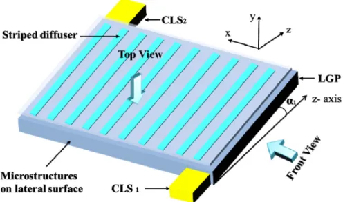
Despite the fact that LEDs are widely used as the light source for the backlight in LCDs, the conventional LED with a Lambertian angular distribution is not suitable for high-directionality backlight in eco-displays [7–9]. Thus, the collimated light source becomes a good candidate for these displays. In the proposed structure, dual point collimated light sources (CLSs) are expanded to planar light sources without degrading their high-directionality. The viewing angle can be switched by the high-directionality backlight with a striped diffuser. An isometric view of the backlight configuration is shown in Fig. 1.
Fig. 1. Isometric view of the backlight configuration. CLS: collimated light source, LGP: light guide plate.
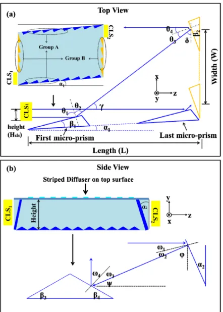
The backlight system includes three parts: a compact light guide plate (LGP) with three groups of micro-prisms located on the lateral and bottom surface, dual CLSs located at the corners of the LGP, and a striped diffuser on the top surface, whose location corresponds to the left side of the micro-prism on the bottom surface, as shown in Fig. 2. The micro-prisms are coated with aluminum film for high reflectance.
The LGP is a parallelogram that lies in the x-z plane, and makes an angle of α1 with the z-axis. Figure 2(a) illustrates the process of light propagation in the x-z plane according to total internal reflection (TIR) theory: the incident light propagating along the z-axis is reflected twice by the micro-prisms of group A and B successively. Since, a point light source is converted to a line light source. In the y-z plane, the left/right surfaces of the LGP make an angle of α2 with the y-axis, except at the incident region of the light source. The light propagation in the y-z plane can be described as follows: the light reflected by group B propagates along the negative z-axis with a tilt angle ψ, then it is reflected to the normal direction by the micro-prisms of group C on the bottom surface, as illustrated in Fig. 2(b). Therefore, a line light source is expanded to a planar light source. Compared with a conventional backlight with LEDs, rays propagating in this novel LGP, with only three times of reflections, have been almost totally coupled out without being trapped in the LGP which significantly benefits for the optical efficiency.
As the backlight works in different viewing angle modes, rays are coupled out from the LGP directly or scattered by the striped diffuser according to the positions where rays emit to the top surface of the LGP. When the backlight works in the narrow viewing angle (NVA) mode, CLS1 is turned on and the CLS2 is turned off. The high-directionality light was reflected towards the normal direction by the right side of micro-prism on bottom surface according to the optical path in LGP and directly passed through the gap of the striped diffuser, as shown in Fig. 3(a). On the other hand, when the backlight works in the wide viewing angle (WVA) mode, CLS2 is turned on and CLS1 is turned off. The light was reflected towards the normal direction by the left side of micro-prism on bottom surface then scattered by the striped diffuser, as shown in Fig. 3(b). Because of the fast response of the light source, rapid switching between the two modes can be easily achieved by alternating the different light sources.
Fig. 2. Light propagation in light guide plate (LGP) along different planes: (a) x-z plane with top view, and (b) y-z plane with side view.
Fig. 3. The switchable viewing angle display works in different modes: (a) narrow viewing angle (NVA) mode, and (b) wide viewing angle (WVA) mode.
According to the geometrical optics theory, the parameters of the LGP can be deduced by the following equations:
In the x-z plane: 1 1 cls 1 1 1 2 3 4 1 1 1 2 3 tan (H / W) tan (W / ) = tan (L/W) (180 ) / 2 (90 ) / 2 90 90 L α γ δ θ θ γ θ θ δ β α θ β δ θ − − − = = = = − = = − = − − = − − (1)
In the y-z plane:
1 1 1 2 3 4 2 2 3 4 3 tan (L / H) tan (H/ L) (90 ) / 2 (90 ) / 2 90 90 ϕ ψ ω ω ϕ ω ω ψ α ϕ ω β β ψ ω − − = = = = − = = − = − − = = − − (2) where Hcls is the height of collimated light source, H, L, and W are the height, length, and
width of the LGP, respectively, as shown in Fig. 2.
3. Results and discussion
In order to verify the effects of the proposed structure, a 3D geometric model of the backlight system was established by ray tracing software: Lighttools 7.2, which employs the Monte Carlo method [10, 11]. Based on the equations in the last section, the parameters of the backlight module were calculated, and are listed below in Table 1.
Table 1. Parameters of the backlight module.
Material / Refractive Index Polymethylmethacrylate (PMMA) / 1.49 Backlight Dimension (L × W × H)(mm) 60 × 84 × 5 α1 /α2 (deg.) 5 / 22.5 β1 / β2 (deg.) 22.5 / 27.5 β3 / β4 (deg.) 43.5 / 43.5 Pitch of micro-prism (μm) 150 Striped diffuser gap (μm) 150 Divergence angle of light source
(FWHM) ± 0.2°
To compare the optical efficiency with the proposed backlight, a conventional backlight whose optical efficiency is normally lower than 70% and light distribution is approximately ± 60°of FWHM which close to that of the Lambertian source has been employed and simulated as the reference [12]. The simulation results showed that the optical efficiency of a conventional backlight was 65%, whereas that of the novel backlight was 89.8% in WVA mode and 95.4% in NVA mode. Compared with the conventional backlight, the optical efficiency of the proposed backlight system increased by a factor of 1.38 and 1.47 for the WVA and NVA modes, respectively, owing to the substantially shortened optical path length. A detailed description of the principle analysis for the novel backlight with high optical efficiency can be explained by the Bouguer Law in our previous work [13].
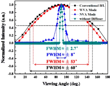
In order to make the simulation conditions well matched with experiment setup, the divergence angle of light source and the radius of vertex angle of micro-prism were set as ± 0.2° of FWHM and 5 um respectively, which were the same as experiment setup. Figure 4 demonstrates that the switchable viewing angle display offered approximately ± 53° of FWHM in WVA mode which was close to that of conventional backlight with ± 60° of FWHM. Though the backlight without diffuser can offer a narrow viewing angle with ± 2.7°
of FWHM, a fraction of light deviated from the striped gap was scattered by the diffuser, which leads to the light distribution broadened from ± 2.7° to ± 8° of FWHM in NVA mode. In order to evaluate the switching capability of the backlight, the proportion of light scattering in NVA mode can be approximately calculated by integrating the intensity of light scattering in NVA mode divided by the total light intensity in all viewing angle, according to the light intensity distributions in Fig. 4. The proportion of high-directionality light in WVA mode can be calculated with the similar treatment. The result shows that proportions of the light scattering in NVA mode and high-directionality light in WVA mode are only about 13.6% and 6.25%, respectively, implying that two kinds of working mode of the backlight can be clearly distinguished with good switching capability. In addition, the luminous intensity distribution was normalized to maintain the same luminance at the normal direction of the backlight in different modes. The novel backlight achieved a luminance of 10035 cd/m2 with only 5 lm of power consumption in the NVA mode as light energy only needs to be devoted to the normal direction. Conversely, in order to maintain the same luminance, 92.5 lm were required in the WVA mode, and 103 lm were required for the conventional backlight because the light energy needs to support all directions. Hence, compared with the conventional backlight, only 5% of power consumption was needed when the novel backlight worked in NVA mode.
Fig. 4. The light intensity distributions of the backlight operating in different modes, and compared with the conventional backlight.
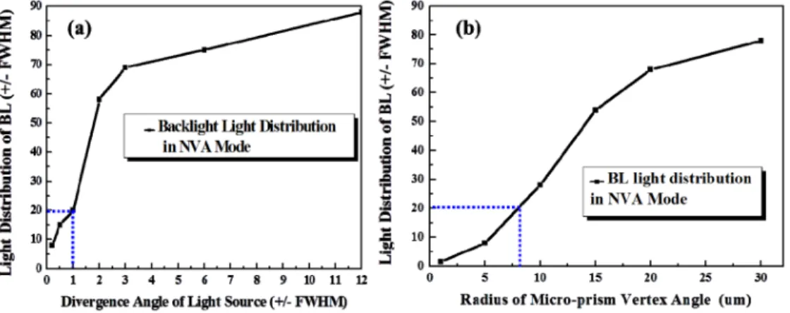
In order to evaluate the tolerance of the backlight, three main parameters—divergence angle of the light source, radius of vertex angle of micro-prism, and shift distance of striped diffuser—were simulated. The simulation result indicated that with the increasing of divergence angle of light source, the backlight light distribution in NVA mode was greatly expanded from ± 8° to ± 84° of FWHM. As the divergence angle of light source increased more than ± 1° of FWHM, the light distribution of the backlight was expanded with a sudden increase by the multiple amplification effect of the micro-prism and striped diffuser, as shown in Fig. 5(a). Therefore, in order to maintain the high-directionality of the backlight in NVA mode (< ± 20°of FWHM), the divergence angle for the light source should be less than ± 1° of FWHM. A high collimated light source with ± 0.2° of FWHM was used in our simulation and experiment to maintain the high-directionality character in NVA mode.
The effect of radius of vertex angle of micro-prism on backlight light distribution was illustrated in Fig. 5(b). As the radius of vertex angle of micro-prism was increased larger than 8 μm, the light was diffused to random direction without being precisely controlled, which
leading to a large light distribution. Thus, the radius of vertex angle of micro-prism should be less than 8 μm to maintain the narrow light distribution (< ± 20°of FWHM) in NVA mode.
Fig. 5. The effect of (a) divergence angle of light source and (b) radius of vertex angle of micro-prism on backlight light distribution.
The striped diffuser is about 30 μm in width and 150 μm in pitch. The schematic diagram of striped diffuser shift and light distribution of the backlight in two modes are illustrated in Figs. 6(a) and 6(b), respectively. In WVA mode, due to the striped diffuser shift, only a part of the light could be scattered by the diffuser, the rest was directly out-coupled and form the light distribution as shown in Fig. 6(b). According to the light intensity in Fig. 6(b), the shift range of striped diffuser should be of less than 5 μm to keep the backlight light distribution still greater than ± 55° of FWHM in WVA mode. Therefore, precisely alignment for the striped diffuser is very essential for the backlight. Patterned the striped diffuser on the LGP directly with precisely alignment could be a good solution to solve this issue.
Fig. 6. (a) Schematic diagram of striped diffuser shift and (b) light distribution of the backlight in two modes.
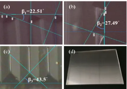
According to the parameters of the backlight system in Table 1, a prototype backlight including a compact light guide plate and three different scattering densities of striped diffusers was fabricated by commercial processes [14]. The micro-prism array’s profiles of each group were measured, as shown in Figs. 7(a)–7(c) and a general view was illustrated in Fig. 7(d). The measurement results indicated that the dimensions of the fabricated backlight were well matched with our pre-design specifications.
Fig. 7. Prototype of the switchable viewing angle backlight. Micro-prism of group A in pane (a), micro-prism of group B in pane (b), micro-prism of group C in pane (c), and the general view in pane (d).
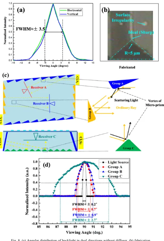
The angular distributions of the backlight in the horizontal and vertical directions without the striped diffuser were measured, as shown in Fig. 8(a). The results demonstrate that when the collimated point light source was expanded to a planar light source by the micro-prism arrays, the backlight offered ± 3.5° of FWHM both in horizontal and vertical directions, which should be as narrow as ± 0.2° of FWHM with ideal condition. Two key issues, vertex angle scattering of the micro-prism and irregularity surface during the fabrication process as illustrated in Fig. 8(b), should be further investigated. However, the light propagating is continuous in LGP and could not be measured separately, thus, using simulation to analyze the system. Three receivers were embedded within the LGP successively according to the light propagation direction, which is Receiver A for Group A, Receiver B for Group B, and Receiver C for Group C, respectively, as shown in Fig. 8(c). Each of the receivers could collect the light reflected by the different groups of micro-prism independently without affecting by the others. The results illustrated in Fig. 8 (d) shows that the light was broadened from ± 0.2° to ± 0.7° of FWHM by the Group A micro-prism, slightly expanded by Group B micro-prism to ± 0.9° of FWHM, and by Group C micro-prism to ± 2.7° of FWHM. For Group A and C, as the vertex angle of micro-prism with 5 μm radius were utilized to reflect light, a part of light was scattered by the radian, which resulted in light distribution broadened. On the contrary, Group B could maintain high-directionally, as most of light was reflected by the smooth surface of micro-prism, as shown in Fig. 8(c). In addition, due to the irregularity surface produced during the fabrication process and some other unpredictable defects which could not simulate in software, the measurement result of light distribution ( ± 3.5° of FWHM) is a little bit larger than that of the simulated result ( ± 2.7° of FWHM).
Fig. 8. (a) Angular distribution of backlight in dual directions without diffuser, (b) fabrication irregularities on micro-prisms, (c) locations of the receivers according to different groups of micro-prism, and (d) light distribution broadened by the different groups of micro-prism.
The striped diffuser was patterned on a polyethylene terephthalate (PET) substrate by a femtosecond pulse laser with a motorized x-y-z micro-positioning stage. The PET substrate was melted by laser radiation to form the inverted conical structures. Scanning electron microscopy (SEM) images with top and cross-sectional views of the striped inverted conical
structures are shown in Figs. 9(a) and 9(b), respectively. The diameter of the inverted conical structure was approximately 30 μm, and the pitch of the strips was approximately 150 μm.
Fig. 9. (a) Top view of scanning electron microscopy (SEM) image of striped inverted cone and (b) cross-sectional view.
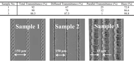
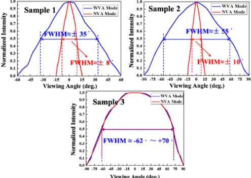
Three diffusers (Sample 1, 2, and 3, respectively) with different scattering abilities were produced by femtosecond laser irradiation on the PET substrate. As shown in Fig. 10, the striped pitch was 150 μm for Sample 1 and Sample 2, which is consistent with our design. However, the pitch was only 15 μm for Sample 3 because of the excessive irradiation. Here, we use haze to evaluate the scattering ability, which is defined as the measured diffused transmittance divided by the total transmittance. A large haze value indicates that the sample has a better scattering ability, so that the light can diffuse to a larger viewing angle. The optical characteristics for three types of diffusers are summarized in Table 2.
Table 2. Optical characteristics for three types of diffusers.
Sample No. Total Transmittance (%) Diffused Transmittance (%) Parallel Transmittance (%) Haze (%)
1 92 67 25 72.8
2 90 78 12 86.6
3 88.5 87.5 1 98.8
Fig. 10. Striped diffuser with different haze.
The angular distribution is the key property of the switchable viewing angle display. The diffuser was tightly attached on the top surface with precise alignment. The characteristics of the high-directionality backlight with different haze diffusers are depicted in Fig. 11. The results illustrate that as the collimated backlight combined with Sample 1, the light distribution expanded from ± 3.5° to ± 8° of FWHM in the NVA mode. As the propagating light was not fully collimated, a fraction of light was scattered by the striped diffuser. In the WVA mode, the light distribution with ± 35° of FWHM was narrower than that of a conventional backlight, as the low haze of Sample 1 is insufficient to scatter light effectively. On the other hand, as the collimated backlight combined with Sample 2, the light distribution
was expanded to about ± 10° of FWHM in the NVA mode for similar reasons. With the increasing haze of Sample 2, the light distribution of the backlight in the WVA mode is ± 55° of FWHM, implying that the proposed backlight can offer functionality similar to that of a conventional backlight for group viewing. Moreover, owing to the excessive radiation, the pitch of Sample 3 was much narrower than that of our design. Therefore, all of the light was scattered by the diffuser and the light distributions in both modes were almost the same. The switchable viewing angle could not function in that case. In conclusion, it is necessary to optimize the haze of the diffuser, and the 86.8% haze of the Sample 2 is an optimal value for switchable viewing angle display.
Fig. 11. Angular distribution of normalized light intensities with different types of diffusers.
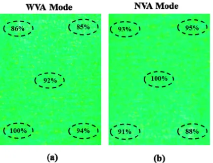
The spatial luminance uniformity – defined as the minimum luminance divided by the maximum luminance – is an important characteristic for the switchable viewing angle display. A green laser (λ = 532 nm) with a homogenized light intensity was employed as a collimated light source. The spatial luminance distributions of the backlight with and without the diffuser were measured by a spectro-radiometer (CS-2000). The speckle issue which caused by coherent laser light source, can be greatly suppressed by employing several methods such as light source modulation with a vibrating diffractive beam shaper [15], temporal averaging by diffractive optical elements [16], and digital image processing [17]. Moreover, using laser as the light source is not must but for convenience with the prototype of switchable viewing angle display. The highly collimated incoherent light source with LEDs, which proposed in our previous work [18], could eliminate this issue. The speckle can be observed owing to the spatial coherence of the laser, yet can be eliminated by using an incoherent light source with high collimation. In order to eliminate the measurement error caused by laser speckle effect, a viewing cone of 0.5° was used to measure the test points. The spatial luminance uniformity after normalization was 85% and 88% in WVA and NVA modes, respectively, as illustrated in Figs. 12(a) and 12(b), respectively.
Fig. 12. The spatial luminance distributions of the backlight in (a) WVA and (b) NVA mode.
4. Conclusions
A switchable viewing angle display with a compact high-directionality backlight and striped diffuser has been demonstrated for applications in eco-display devices. Compared with the conventional backlight module, the proposed construction exhibited the optical efficiency increased by a factor of 1.38 with a spatial uniformity 85% in the WVA mode and a factor of 1.47 with a spatial uniformity 88% in the NVA mode. It can offer ± 55° of FWHM in the WVA mode, which is similar to that of the conventional backlight and offer ± 10° of FWHM in the NVA mode which only needs 5% power consumption to maintain the same luminance as a conventional backlight. As a consequence, the compact backlight with switchable viewing angle demonstrates potential for high-efficiency eco-display applications.
Acknowledgments
This work was supported in part by 973 program (2013CB328804), and by NSFC (61275026). I would also need to thank Shi-hong Ouyang for his effort in coating high reflectance aluminum film on the micro-prism.