Fuzzy Optimization Techniques Applied to the
Design of a Digital PMSM Servo Drive
Kuang-Yao Cheng, Student Member, IEEE, and Ying-Yu Tzou, Member, IEEE
Abstract—This paper presents a novel design approach by
applying gradient optimization with fuzzy step-sizing techniques to the design of a digital permanent magnet synchronous motor (PMSM) servo drive. The servo specifications and design variables are specified and analyzed to formulate a controller optimization problem. The servo responses are then fed back to evaluate the overall system performances, which can be expressed as objective functions with respect to the servo control parameters. According to the objective functions and design specifications, the servo control parameters can be properly tuned toward their optimal values by using the proposed optimization techniques. In order to improve the convergent rate of the optimization process, a fuzzy-logic based step-size tuning strategy is presented. Because of the nonlinear property of the digital servo drives, the tuned servo control parameters may be only optimal for a particular operating point, therefore, once the optimum design is achieved, the proposed fuzzy optimizing controller can perform as an intelligent tuner for on-line gain adaptation under different loading conditions. The proposed fuzzy optimization servo tuner has been realized under a PC-MATLAB-based environment with an on-line controlled digital PMSM servo drive. Simulation and experimental results indicate that the control parameters of a digital PMSM servo drive can be optimized for its dynamic responses under various load conditions.
Index Terms—Controller optimization, digital permanent
magnet synchronous motor (PMSM) servo drive, fuzzy step-size tuning strategy.
I. INTRODUCTION
A
LTHOUGH high performance permanent magnet syn-chronous motor (PMSM) servo drives are increasingly employed in industrial automation and home appliances, the design of these servo drives still requires time-consuming trial and error processes during its final tuning stage to fulfill the application requirements. In practice, the design of a digital PMSM servo drive involves several complex procedures which include modeling, control scheme design, servo loop analyzes, simulation, digital implementation, and parameter tuning. Hence, application of intelligent optimization techniques for simplifying the design problem remains an interesting and important issue to be further studied.Usually, parameter tuning which plays an important role in improving the overall servo performance is very time-con-Manuscript received July 23, 2002; revised October 3, 2003. This work was supported by the National Science Council of Taiwan, R.O.C., under Project NSC90-2622-E009-002. Recommended by Associate Editor A. M. Trzynadlowski.
The authors are with the Power Electronics and Motion Control Laboratory, Department of Electrical and Control Engineering, National Chiao-Tung University, Hsinchu 300, Taiwan, R.O.C. (e-mail: brian.ece88g@nctu.edu.tw; yytzou@mail.cc.nctu.edu.tw).
Digital Object Identifier 10.1109/TPEL.2004.830036
suming because of the diverse applications of the servo drives. In order to reduce the parameter tuning efforts, many papers in the literature have presented different approaches and control structures for designing the servo controllers during recent years [1]–[10]. A tuning procedure of the gains of a proportional-integral (PI) speed controller for induction motors has been proposed in [1]. By utilizing a simple frequency-do-main test, the PI gains can be suitable chosen. However, this method is only valid in linear operating range. In a practical servo system, many nonlinear constraints are imposed by the drive and load. In [2], Lin has proposed a design approach for a real-time integral-proportional (IP) position controller. Although the IP position controller can be real-time designed according to the estimated motor parameters, there still exist some tuning problems because of the nonlinear relationship of the design equations. In [3], a feedforward controller, which can be tuned automatically by using a disturbance torque observer based on the dynamic equations of the plant, has been proposed. However, because nonlinear characteristics of the power converter have been neglected in its linear dynamic model, the estimated disturbance torque can be much larger than the real disturbance torque. This over estimation may result in a severe overshoot in a large step response.
A heuristic auto-tuning control scheme for the velocity and current control loops of electric drives has been proposed in [4]. The proposed scheme is robust for large plant uncertain-ties. However, it is time-consuming when more than two control parameters need to be tuned. Besides, a model-free approach for tuning of PI controllers for high-performance PMSM drives has been in [5]. However, this approach can be only used for a single-loop tuning. In [6], Tan et al. presented a combinational control scheme of an iterative learning feedforward controller and a conventional PID controller for a precise motion con-trol of permanent magnet linear motors, and developed a relay auto-tuning method to automatically derive the control param-eters. However, for systems with unpredictable torque distur-bances and load variations, the well compensated feedforward controller may result in extraordinary transient oscillations.
Furthermore, intelligent control techniques have been applied for designing digital servo drives [7]–[10]. For examples, the expert systems and fuzzy logics have been adopted for servo systems to enhance control performances [7], [8]. Besides, the learning capability of artificial neural-network has also been uti-lized to make the digital servo drives to be more intelligent. In [9], an artificial-neural-network (ANN)-based self-tuning PI control scheme has been proposed for training the servo troller to fulfill the design requirements at each operating con-ditions. In addition, an IP position controller with on-line gain-0885-8993/04$20.00 © 2004 IEEE
Fig. 1. Control block diagram of a typical digital PMSM drive system.
tuning strategy using a recurrent fuzzy neural network (RFNN) has been proposed in [10]. Although these intelligent schemes seem to be effective in some prescribed situations, they still need sophisticated training and are restricted by their economic unfeasibility.
In this paper, a novel approach is presented by applying a gradient optimization with fuzzy step-sizing techniques to de-sign a digital PMSM servo drive for optimizing servo control performance. Optimization techniques offer a systematic way to approach the design problem [11], [12], and provide a better understanding of the design tradeoffs. Besides, fuzzy-logic of-fers the opportunity to transfer the expert-knowledge into an al-gorithm to adaptively control the tuning step sizes to improve the convergent rate of the overall optimization process. The re-search goal of this paper is to find the optimal settings for each servo control parameter. Furthermore, because of the nonlinear property of the digital servo drives, the optimized servo control parameters may be optimal for a particular operating point, but not for other operating conditions. Therefore, once the optimum design is achieved, the proposed fuzzy optimizing controller can also act as an intelligent controller for on-line gain adaptation under different load conditions.
The paper is organized as follows. In Section II, the overall servo control loops are analyzed to formulate an optimization problem for designing digital servo drives. A weighted-sum optimization algorithm is proposed in this section for solving the design problem. In Section III, the convergence of the proposed algorithm is analyzed, and a novel fuzzy step-size tuning strategy for the optimization problem is presented and described in detail. Some simulation and experimental results are given to illustrate the effectiveness of the proposed fuzzy optimization strategy in Section IV. Finally, concluding remarks are given in Section V.
II. OPTIMIZATION PROBLEM FORMULATION FORSERVOCONTROL
Fig. 1 shows the control block diagram of a typical digital PMSM servo drive system, which consists of a PMSM with load, a ramp-comparison current-controlled pulsewidth mod-ulation (PWM) voltage-source inverter (VSI), a field-orienta-tion mechanism, which is used for decoupling the torque- and
flux-producing currents in PMSM [13], and a servo control loop with an industrial standard digital servo controller [14]. For a high-performance PMSM servo drive, each control parameter needs to be tuned to fulfill the design specifications. In general, lower servo control loop gains decrease the system robustness to load disturbance, and higher servo control loop gains improve responsiveness, but move the system closer to instability. Nor-mally, the principle of servo control loop tuning [15] is to raise the control loop gains as high as possible without causing in-stability. However, the tuning problem can be challenging be-cause there are four servo control gains: the position loop pro-portional gain , the position loop feedforward gain , the velocity loop proportional gain and the velocity loop integral gain . Hence, for such a multidimensional design problem, using the “trial-and-error” method for tuning may ab-sorb a lot of time.
Fortunately, each servo control parameter plays a different role for servo performance. Once the relationship between the servo control gains and servo performance can be understood, the multidimensional optimization problem can be properly de-coupled, and each control gain can be tuned independently.
A. Servo Control Loop Analysis
The control law for position control loop can be represented as
(1) where
desired position command at the th sampling interval;
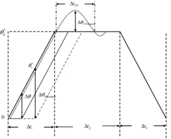
rotor position feedback at the th sampling interval; rotor speed command at the th sampling interval. For a periodic quick positioning system, a typical motion control profile is usually adopted as shown in Fig. 2. The increasing slew rate of the motion command is the target speed command
which can be derived as
(2) where is the target position, and is the acceleration time interval. Then, the position following error can be
formu-Fig. 2. Typical motion control profile of quick positioning systems.
lated from the target speed and the position loop proportional gain as the following equation:
(3) Hence, for a given motion control profile, i.e., is given, if the proportional gain increases, the position following error then decreases correspondingly. In other words, a higher posi-tion loop gain can provide better dynamic response for tracking ability and better robustness for disturbances rejection. How-ever, higher loop gain may cause excessive overshoot response or instability condition as also indicated in Fig. 2. The feedfor-ward path of the position loop can help to improve the tracking ability and reduce position following error instead of using a high position loop gain. Since the feedforward path works out-side the position control loop and directly takes the position command to the velocity control loop, it doesn’t cause insta-bility. However, the primary shortcoming of feedforward path is that high gain may induce overshoot response.
In general, the position response is highly dependent on the inner velocity loop bandwidth. Usually, the relationship between the position loop gain and the bandwidth of the velocity control loop can be specified as [16]
(4) where is the bandwidth of the velocity control loop. It can be seen from (4) that in order to increase the position control loop gain, the inner velocity loop should be well-tuned.
Fig. 3 shows an ideal step response of velocity control loop and the corresponding control effort. The control law for ve-locity control loop can be represented as
(5) (6) where
rotor speed feedback at the th sampling interval; rotor speed error at the th sampling interval;
Fig. 3. Typical control profiles for step velocity control. torque current command at the th sampling interval.
The objective of the velocity controller is to generate an appro-priate torque command for speed tracking. A high gain in the velocity loop can improve the transient performance. However, too large gain may also cause an overshoot in the speed response as indicated in Fig. 3.
B. Performance Evaluation
In order to specify the relationship between the servo control parameters and servo performance, a performance evaluation method is presented. First, for the position control loop, two ob-jective functions are defined to evaluate the position response as
(7)
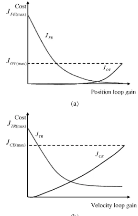
(8) with two matrices (9)–(11), shown at the bottom of the next page, where is one iteration period of the optimization process, and is the discrete sampling period for the servo con-trol loop. and denote the objective functions of the position following error and overshoot at the cycle, re-spectively. From the previous analyzes of the servo control loop,
the relationship between these two objective functions and po-sition loop gains can be described as shown in Fig. 4(a). With small position loop gains, the following error may be very large. As increasing position loop gains, the following error may de-crease, but the overshoot may increase.
For velocity control loop, two additional objective functions are defined for evaluating the speed dynamic response as
(12)
(13)
with two matrices (14) and (15), as shown at the bottom of the page, where and denote the objec-tive functions of the speed transient response and the corre-sponding control effort at the cycle, respectively. The de-sired rise time of speed response can be determined when the rotor speed is greater than . The relationship between these cost functions and velocity loop gains can be described as shown in Fig. 4(b). With small velocity loop gains, the control effort is small and the speed response is very slow. By increasing the velocity loop gains, the transient speed error may decrease to a minimum value with increasing the control effort.
C. Optimization Algorithm
After defining these objective functions, the design problem for high-performance servo drives becomes as a multiobjective optimization problem, which implies to minimize all these four objective functions simultaneously. Since there are some trade-offs between these objective functions, the multiobjective opti-mization problem is difficult to be solved. In order to solve this problem, a weighted-sum method [17] is presented for repre-senting the relative importance of each objective function. By properly combining the weighted objective functions, a convex
(a)
(b)
Fig. 4. Relationship between objective functions and servo loop gains: (a) position control loop (b) velocity control loop.
objective function can be formulated for determining the op-timal values of servo control parameters as
(16)
where , and
is a weighting vector, which is used to specify the performance specifications. Hence the optimization problem can be reformu-lated as
subject to (17)
where is the control parameter
vector. and are the maximum and minimum vectors of . Since the determination for the weighting vector is very critical for the optimization performance, the weighting vector should be properly specified. In this study, a method for determining the weighting vectors of each control loop is presented based on the physical considerations of design specifications. (9) (10) (11) (14) (15)
For the position control loop, the most two important perfor-mance indices are the position following error and overshoot. Therefore, the weighting vector for position control loop can be chosen as
(18) where and can be specified as
(19) where and denote the maximum allowable following error cost and overshoot cost, respectively. They can be approximated from the desired motion control profile as the following equations:
(20) (21) where
maximum allowable following error; maximum overshoot;
time interval to the maximum overshoot. Hence, the combined objective function for evaluating position control performance can be rewritten as
(22) where can be arbitrarily assigned.
For the velocity control loop, the most two performance in-dices are the speed transient response and the control effort. Therefore, the weighting vector for the velocity loop can be chosen as
(23) where and can be specified as
(24) where and denote the maximum allowable speed transient response cost and control effort cost, respec-tively, and can be approximated from Fig. 3 as the following equations:
(25) (26)
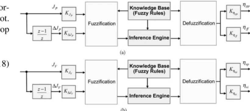
Fig. 5. Block diagram of the fuzzy step-size tuners: (a) position control loop and (b) velocity control loop.
Therefore, the combined objective function for evaluating ve-locity control performance can be rewritten as
(27) where can be arbitrarily assigned.
Since the combined objective functions are convex functions, the gradient method can be applied to find the optimal control parameters for minimizing the objective functions [11]. The up-date equations for each control parameter are
(28) (29) (30) (31) where denotes the current iteration number, and , , , and are the step sizes for the optimization equations. In gen-eral, small step sizes may lead to an inefficient search process. On the other hand, large step sizes allow the search process to approach the minimum efficiently. However, large step sizes may not guarantee the descent direction for optimization and may cause oscillation around the local minimum point. Several methods have been proposed to adaptively adjust the step sizes during the optimization process [12]. For example, the steepest descent algorithm can be applied to choose the optimal step size for the maximum decreasing amount of the objective function at each increment. However, this method needs to calculate the objective values with many different step sizes and may slow the overall optimization process. In this paper, a fuzzy step-size tuning strategy is proposed to adaptively update the step sizes for achieving both fast convergent rate and precise optimum re-sults of the optimization process. Since fuzzy-logic can simply transfer the expert-knowledge into an algorithm by using lin-guistic descriptions, the proposed strategy can best extract the expert’s knowledge.
III. FUZZYSTEP-SIZETUNINGSTRATEGY
A. Convergence Analysis
In theory, the property of convergence of any iterative proce-dure is very important. Hence, the convergence of the proposed optimization algorithm is analyzed. By setting , the gradient of the position control loop cost can be derived from (22) without loss of generality as
(32) Define a discrete Lyapunov function [18] as
(33) where denote the -cycle position error vector, and can be expressed as
(34) The change of the Lyapunov function is obtained by
(35)
By defining and
, the error difference due to the optimization can be represented by
(36)
Then the norm of the position error vector can be derived as
(37) where is a identity matrix. Therefore, from the Lya-punov stability theorem, the asymptotic convergence is guaran-teed if is chosen to satisfy
(38) with
(39) Similar analysis can be done for the feedforward
con-troller by defining and
, and the asymptotic convergence is guaranteed if is chosen to satisfy
(40) with (41), shown at the bottom of the page.
For the velocity loop optimization, the gradient of the ve-locity control loop can be derived from (27) by setting
without loss of generality as
(42)
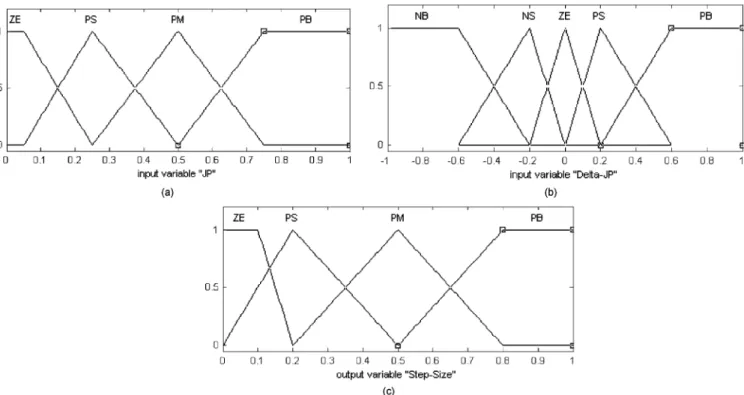
Fig. 6. Membership functions of fuzzy step-size tuner: (a) combined objective functions, (b) change of combined objective functions, and (c) step sizes.
Define a discrete Lyapunov function as
(43) The change of the Lyapunov function is obtained by
(44)
By defining and
, the error difference due to the optimization can be represented by
(45)
(46)
Then the norm of the sum of the speed error vector and the control effort vector can be derived as
(47) Therefore, the asymptotic convergence is guaranteed if is chosen to satisfy
(48) with
(49) Similar analysis can be done for the integral controller by
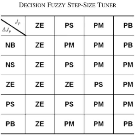
Fig. 7. Output surface of the fuzzy step-size tuner. TABLE I
DECISIONFUZZYSTEP-SIZETUNER
, and the asymptotic convergence is guar-anteed if is chosen to satisfy
(50) with
(51)
B. Fuzzy Step Size Tuner
Fig. 5 shows the detailed block diagram of the fuzzy step-size tuners for optimization algorithms. The inputs of the fuzzy step-size tuners are the combined servo loop objective function and , and the change of the combined
objective functions and
Fig. 8. Hierarchical fuzzy optimization scheme for servo control systems. TABLE II
RATINGS ANDPARAMETERS OFPMSM SERVODRIVE
. The output variables are the step sizes for updating servo control parameters. The input and output linguistic-variables of the fuzzy tuner are quantized in subsets as follows:
1) objective function: zero (ZE), positive small (PS), posi-tive medium (PM), posiposi-tive big (PB);
2) change of objective function: negative big (NB), negative small (NS), zero (ZE), positive small (PS), positive big (PB);
3) step sizes for optimization: zero (ZE), positive small (PS), positive medium (PM), positive big (PB).
Fig. 9. Performance surfaces of position loop gains with fixed velocity loop gains: (a)J , (b) J , and (c)J . Since the objective function and the step sizes are always
positive, the universes of discourses for these variables are normalized in the interval . The universe of discourse for the change of objective function is normalized in the interval . Uniformly distributed triangular functions are adopted as the membership functions for input and output linguistic-variables as shown in Fig. 6. According to servo loop analyzes, the linguistic decision rules for the input-output relationship are summarized in Table I. Besides, Zadeh’s com-positional rule of inference and the standard center of gravity (COG) defuzzification technique are used to obtain the crisp output. Fig. 7 shows the output surface of the fuzzy step-size tuner. As shown in the figure, the step sizes for optimization can be adjusted based on the objective values. By using this strategy, the local minimum conditions with large objective values due to the nonlinear characteristics of power converter and drive’s load can be avoided.
Since the scaling factors for the fuzzy step-size tuner have crucial influence on the performance of the optimization process, the input and output gains are determined based on
practical considerations instead of using conventional trial and error procedure. The input gains for position control loop are chosen as
(52) (53) where is the desired position following error. In such a way, the normalized input objective function is bounded be-tween . Furthermore, in order to preserve the convergence property of the gradient method, the tuning step sizes for the servo control parameters should be limited. The output gains for updating the tuning step sizes of the position control param-eters are
(54) (55)
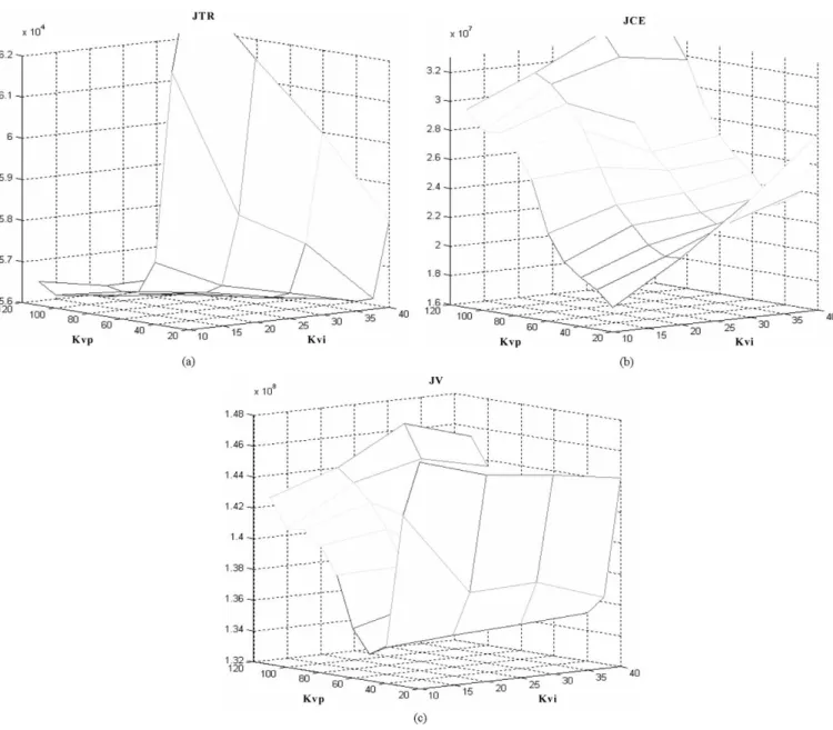
Fig. 10. Performance surfaces of velocity loop gains with fixed position loop gains: (a)J , (b) J , and (c) J . where is the maximum output from the fuzzy-tuner based on
the COG defuzzification method. The input gains for velocity control loop are chosen as
(56) (57) The output gains for updating the tuning step sizes of the ve-locity control parameters are
(58) (59) Fig. 8 shows the block diagram of the proposed fuzzy op-timization scheme for a servo control system. This scheme is composed of a two-level hierarchical architecture. The higher level is the proposed fuzzy optimization algorithm, which exe-cutes in a batch processing mode with lower priority, and the
lower level is the servo control system, which operates in a real-time processing mode with higher priority. By using the hi-erarchical structure in realizing the fuzzy-logic based optimiza-tion techniques for digital servo drives, the benefits of computa-tional efficiency and learning capabilities of intelligent control strategy can be combined [19].
IV. SIMULATION ANDEXPERIMENTALRESULTS In order to verify the effectiveness of the proposed fuzzy op-timization strategy, some simulations and experiments are re-ported in this section. The ratings and parameters of the PMSM servo drive are listed in Table II.
A. Performance Surfaces
Fig. 9 shows the simulation result of performance surfaces of position loop gains with fixed velocity loop gains. Fig. 10 shows the simulation result of performance surfaces of velocity loop gains with fixed position loop gains. From these figures, by using the proposed performance evaluation strategy, the servo
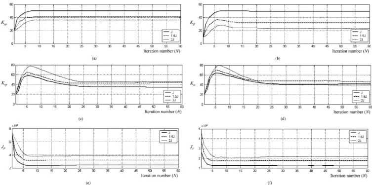
Fig. 11. Optimization process with fixed and fuzzy step sizes: (a)K , (b) K , (c) K , (d) K , (e) J , and (f) J .
Fig. 12. Optimization process with various inertiasJ : (a) K , (b) K , (c) K , (d) K , (e) J , and (f) J .
performance can be formulated as two convex objective func-tions for optimizing the servo control parameters. The minimum regions of the convex objective functions are the desired servo control parameters. By changing the objective weighting vec-tors, the minimum regions can be specified to fulfill different design requirements.
B. Step-Size Effects
Fig. 11 shows the simulated optimization process of servo control parameters with small and large step sizes. As shown in
this figure, the tuning step sizes have crucial effects to the op-timization performance. With small step sizes, the convergent rate of the optimization process is very slow, and local min-imum problems may occur. By contrast, the convergent rate can be improved with large step sizes. However, some oscillating and unstable conditions may occur with large step sizes. Fig. 11 also indicates the optimization process of the same initial servo control parameters with the proposed fuzzy step-size tuner. By using the proposed fuzzy step-size tuning strategy, the conver-gent rate of the optimization process can be improved without causing oscillation around the optimal region. Besides, since the
tuning step sizes for the optimization algorithms can be adap-tively adjusted, some local minimum problems can be avoided during the optimization process.
C. Varying Load Inertias
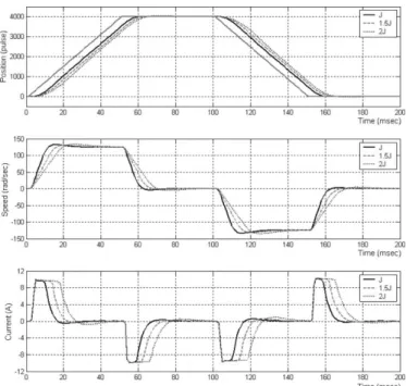
Since the tuning problem of servo control loops heavily depends on the load inertia, the presented fuzzy optimization strategy should be verified with different load inertias. In general, a servo control system can be tuned for optimal performance under one load inertia condition, but may become sluggish or even unstable when the load inertia changes. Therefore, the servo control gains should be re-optimized for different load inertias. Fig. 12 shows the simulation result of the optimization process with the proposed fuzzy step-size tuner under different load inertia conditions. From this figure, the servo control parameters can be optimized toward the minimum objective functions. It should be noted that since the load inertia can be thought as a control gain, the position loop gains may need reducing when the load inertia increases. Fig. 13 shows the simulation result of optimized servo performance with different load inertias.
D. Nonlinear Load Test
In order to make the design optimization problem relevant to real world nonlinearities, a load that contains nonlinearities [20] is applied to the PMSM servo drives. Fig. 14 shows the simula-tion result of the optimizasimula-tion process with the proposed opti-mization algorithm under a nonlinear load test. From this figure, the optimization can still work regardless the nonlinearities of the system. Fig. 15 shows the improvement of the motion con-trol performance with the optimization algorithm.
E. Comparison With Other Methods
Since the PI controller, which is used as the speed con-troller in this paper, is the most commonly used control algorithm, many auto-tuning techniques have been proposed for optimizing the PI control parameters [21], [22]. The relay auto-tuning [23], [24], which has been widely adopted in commercial auto-tuners, is the simplest method of auto-tuning techniques because this method does not need any prior information about the plant dynamics. The relay auto-tuning is based on the observation that a system with a phase lag of at least at high frequency may oscillate with the period under relay control. Once the information of the ultimate gain
and period of the closed-loop system can be determined, Ziegler–Nichols (Z–N) [25] or the refined Z–N tuning rules [26] can be adopted to tune the PI controller. Fig. 16 shows the comparison of the speed control performance with three different tuning rules. From this figure, the Z–N method gives a very oscillatory response with an overshoot of 36%. This is due to the high controller gain. On the other hand, the refined Z–N method reduces the overshoot, but gives a too small integral action to compensate the steady-state error. For the proposed optimization method, since the control effort is taken as a performance index in the algorithm, the undesired oscillation, i.e., the overshoot, can be minimized to achieve
Fig. 13. Simulation results of optimized servo performance with different inertiaJ .
better performance. Most auto-tuning techniques can be only applied to the single-loop PI controller. Very little has been reported in the literature on the development of auto-tuning techniques for cascaded control loops [27]. The tuning of cascaded control loops involves developing of hierarchical tuning strategy. Interactions between different control loops are inevitable. In this paper, a novel optimization approach is proposed to simultaneously tune the cascaded position and speed control loops.
In summary, the proposed optimization technique has sev-eral attractive features. Firstly, by using the weighted-sum ap-proach for the objective functions, the relative importance of the objective functions can be specified for different applica-tion purposes. Secondly, the proposed optimizaapplica-tion algorithm is a model-free approach, which is very practical for many mo-tion control applicamo-tions. Thirdly, the optimizamo-tion for cascaded control loops can be achieved without separating each control loop. Fourthly, though the standard motion control scheme [14] is adopted as an example in this paper, the proposed fuzzy opti-mization algorithm is actually independent to the controller ar-chitecture. The control parameter vector of the formulated optimization problem in (17) can be redefined for other control schemes. It should be noted that more parameters defined in would cause more complicated optimization problems.
F. Experimental Results
Trapezoidal motion profiles for position or velocity control of a servo drive are very typical in practical servo applications. These motion profiles can be used to test a servo system with maximum accelerating rate without overshoot with specified following error.
Fig. 17 shows the experimental result of the optimization process for position control loop. The cost function is defined as the summation of the error square of the position errors. From
Fig. 14. Optimization process with a nonlinear load: (a)K , (b) K , (c) K , (d) K , (e) J , and (f) J .
Fig. 15. Simulation results of optimized servo performance with a nonlinear load.
this figure, the position following error can be minimized to-ward the desired value without causing overshoot response. In practical applications, the servo drive may encounter different load inertia and friction, the servo drives are usually required to reach its maximum response without overshoot. With a speci-fied motion profile, the proposed servo tuner can tune its control parameters to reach an optimal response.
Fig. 18 shows the experimental result of the optimization process for velocity control loop. Using the proposed optimiza-tion strategy, both fast transient response and small control ef-fort can be achieved. It can be observed the current responses are
Fig. 16. Comparison of speed step responses with difference tuning methods.
constrained and this reveals that the proposed tuning scheme is feasible under nonlinear constraint conditions.
V. CONCLUSION
A novel fuzzy optimization strategy for designing digital PMSM servo drives has been presented. Based on the anal-ysis of the servo control loop, an optimization problem is formulated to find the optimal value for each servo control parameter. Using the fuzzy-logic linguistic description, ex-pert knowledge for optimizing control parameters can be con-verted into a fuzzy step-size tuner to improve the convergent rate of the overall optimization process. In comparison with some existing tuning control schemes for servo applications,
Fig. 17. Experimental results of optimization process for position control loop: (a) position response, (b)J , (c) J , (d)K , and (e) K .
Fig. 18. Experimental results of optimization process for velocity control loop: (a) speed response, (b) control effort, (c)J , (d) J , (e) K , and (f) K .
the proposed tuning scheme has advantages of robust perfor-mance and guaranteed stability. The defined objective func-tion for a mofunc-tion profile optimizafunc-tion is consistent with prac-tical applications. The developed tuning scheme can be used
for the on-tuning of a servo drive under real operating condi-tions. From the simulation and experimental results, the servo control parameters can be successfully optimized to fulfill the performance requirements under various load conditions.
REFERENCES
[1] G. W. Chang, G. E. Perez, E. Mendes, and R. Ortega, “Tuning rules for the PI gains of field-oriented controllers of induction motors,” IEEE
Trans. Ind. Electron., vol. 47, pp. 592–602, June 2000.
[2] F. J. Lin, “Real-Time IP position controller design with torque feedfor-ward control for PM synchronous motor,” IEEE Trans. Ind. Electron., vol. 44, pp. 398–407, June 1997.
[3] S. Kobayashi, I. Awaya, H. Kuromaru, and K. Oshitani, “Dynamic model based auto-tuning digital servo driver,” IEEE Trans. Ind.
Electron., vol. 42, pp. 462–473, Oct. 1995.
[4] K. Y. Cheng, S. Y. Lin, and Y. Y. Tzou, “OnLine auto-tuning of a DSP-controlled BLDC servo drive,” in Proc. IEEE PESC’01 Conf., 2001, pp. 1683–1688.
[5] M. Tursini, F. Parasiliti, and D. Zhang, “Real-Time gain-tuning of PI controllers for high-performance PMSM drives,” IEEE Trans. Ind.
Ap-plicat., vol. 38, pp. 1018–1026, July/Aug. 2002.
[6] K. K. Tan, H. Dou, Y. Chen, and T. H. Lee, “High precision linear motor control via relay-tuning and iterative learning based on zero-phase fil-tering,” IEEE Trans. Contr. Syst. Technol., vol. 9, pp. 244–253, Mar. 2001.
[7] J. Litt, “An expert system to perform on-line controller tuning,” IEEE
Contr. Syst. Mag., vol. 11, pp. 18–23, Apr. 1991.
[8] J. Yoshitsugu, K. Inoue, and M. Nakaoka, “Fuzzy autotuning scheme based on alpha-parameter ultimate sensitivity method for ac speed servo system,” IEEE Trans. Ind. Applicat., vol. 36, pp. 492–499, Mar./Apr. 2000.
[9] G. J. Wang, C. T. Fong, and K. J. Chang, “Neural-network-based self-tuning PI controller for precise motion control of PMAC motors,” IEEE
Trans. Ind. Electron., vol. 48, pp. 408–415, Apr. 2001.
[10] F. J. Lin and C. H. Lin, “On-Line gain-tuning IP controller using RFNN,”
IEEE Trans. Aerosp. Electron. Syst., vol. 37, pp. 655–670, Apr. 2001.
[11] E. K. P. Chong and S. H. Zak, An Introduction to Optimization. New York: Wiley, 1996.
[12] J. S. R. Jang, C. T. Sun, and E. Mizutani, Neuro-Fuzzy and Soft
Com-puting. Englewood Cliffs, NJ: Prentice-Hall, 1997.
[13] D. W. Novotny and T. A. Lipo, Vector Control and Dynamics of AC
Drives. New York: Oxford Univ. Press, 1996.
[14] R. D. Lorenz, Advanced Motion Control Technology (State
Con-trol, Observers, Self-Sensing, Fuzzy Logic, Neural Nets), Course Note. Madison, WI: Univ. Wisconsin Press, 1998.
[15] G. Ellis, Control System Design Guide, 2nd ed. San Diego, CA: Aca-demic, 2000.
[16] H. Gross, Ed., Electrical Feed Drives for Machine Tools. New York: Wiley, 1983.
[17] Carlos, M. Fonseca, and P. J. Fleming, “Multiobjective optimization and multiple constraint handling with evolutionary algorithms-part I: A unified formulation,” IEEE Trans. Syst., Man, Cybern. A, vol. 28, pp. 26–37, Jan. 1998.
[18] K. Ogata, Discrete-Time Control Systems, 2nd ed. Englewood Cliffs, NJ: Prentice-Hall, 1995.
[19] F. Karray, W. Gueaieb, and S. Al-Sharhan, “The hierarchical expert tuning of PID controllers using tools of soft computing,” IEEE Trans.
Syst., Man, Cybern. B, vol. 32, pp. 77–90, Feb. 2002.
[20] J. E. McInroy and S. F. Legowski, “Using power measurements to di-agnose degradations in motor drivepower systems: A case study of oil-field pump jacks,” IEEE Trans. Ind. Applicat., vol. 37, pp. 1574–1581, Nov./Dec. 2001.
[21] K. J. Astrom, Automatic Tuning of PID Regulators. New York: Instru-ment Soc. Amer., 1988.
[22] P. J. Gawthrop and P. E. Nomikos, “Automatic tuning of commercial PID controllers for single-loop and multiloop applications,” IEEE Contr.
Syst. Mag., vol. 10, pp. 34–42, Jan. 1990.
[23] C. C. Hang and K. K. Sin, “A comparative performance study of PID auto-tuners,” IEEE Contr. Syst. Mag., vol. 11, pp. 41–47, Aug. 1991. [24] W. K. Ho, C. C. Hang, and J. H. Zhou, “Performance and gain and phase
margins of well-known PI tuning formulas,” IEEE Trans. Contr. Syst.
Technol., vol. 3, pp. 245–248, June 1995.
[25] J. G. Ziegler and N. B. Nichols, “Optimum settings for automatic con-trollers,” Trans. ASME, vol. 65, pp. 433–442, 1943.
[26] C. C. Hang, K. J. Astrom, and W. K. Ho, “Refinements of the Ziegler-Nichols tuning formulas,” Proc. Inst. Elect. Eng. D, vol. 134, pp. 260–263, Mar. 1991.
[27] C. C. Hang, A. P. Loh, and V. U. Vasnani, “Relay feedback auto-tuning of cascade controllers,” IEEE Trans. Contr. Syst. Technol., vol. 2, pp. 42–45, Mar. 1994.
Kuang-Yao Cheng (S’01) was born in Taipei,
Taiwan, R.O.C., in 1977. He received the B.S. degree in electrical engineering from National Sun Yat-Sen University, Kaohsiung, Taiwan, in 1999 and the Ph.D. degree in electrical and control engineering from National Chiao-Tung University, Hsinchu, Taiwan, in 2003.
His research interests are in the areas of DSP motor control, sensorless algorithm design, digital controller realization, and intelligent optimization techniques.
Ying-Yu Tzou (S’81–M’88) was born in Taiwan,
R.O.C., on February 13, 1956. He received the B.S. and M.S. degrees in control engineering and the Ph.D. degree in electrical engineering from National Chiao-Tung University (NCTU), Hsinchu, Taiwan, in 1978, 1983, and 1987, respectively.
From 1980 to 1981, he was with the Electronic Re-search and Service Organization (ERSO), Industry Technology Research Institute (ITRI) as a Design En-gineer in the Control System Department. From 1983 to 1986, he was with Microtek Automation, Inc., as a Project Manager for the development of a computer numerical controller (CNC) for machine tools. He is currently a Professor with the Department of Electrical and Control Engineering, NCTU, and also serves as an industrial consultant for many local power electronics and automation companies. His special inter-ests are sensorless ac drives, intelligent UPS, PV inverters, FPGA-based control ICs for motor drives, high-speed digital system design, and DSP applications in power electronics and motion control.