Electrically tunable wettability of liquid
crystal/polymer composite films
Yi-Hsin Lin1,Hongwen Ren2, Yung-Hsun Wu2, Shin-Tson Wu2,Yue Zhao3, Jiyu Fang3, and Hung-Chun Lin1
1Department of Photonics and Institute of Electro-Optical Engineering, National Chiao Tung University,
1001 Ta Hsueh Rd., Hsinchu 30050, Taiwan
2College of Optics and Photonics, University of Central Florida, Orlando, Florida 32816, USA 3Advanced Materials Processing and Analysis Center and Department of Mechanical, Materials and Aerospace
Engineering, University of Central Florida, Orlando, Florida 32816, USA
[email protected] http://www.cc.nctu.edu.tw/~yilin
Abstract: An electrically tunable wettability in a liquid crystal/ polymer composite film is demonstrated, in which liquid crystal molecules are anchored among polymer grains. The tunable wettability of the composite films originates from the reorientation of the anchored liquid-crystal molecules, which is switched by an in-plane electric field with squared pulses of voltages. These liquid crystal/polymer composite films with electrically tunable wettability have potential applications in polarizer-free displays, ink-jet printing, microfluidic devices, and lab-on-a-chip.
©2008 Optical Society of America
OCIS codes: (230.3720) Liquid-crystal devices; (160.5470) Polymers.
References and links
1. T. P. Russel, “Surface-responsive materials,” Science 297, 964-967 (2002).
2. Y. Liu, L. Mu, B. Liu, and J. Kong, “Controlled switchable surface,” Chem. Euro. J. 11, 2622-2631 (2005). 3. S. L. Gras, T. Mahmud, G. Rosengarten, A. Mitchell, and K. Kalantar-zadeh, “Intelligent control of surface
hydrophobicity,” Chemphyschem. 8, 2036-2050 (2007).
4. X. Feng and L. Jiang, “Design and creation of superwetting/antiwetting surfaces,” Adv. Mater. 18, 3063-3078 (2006).
5. M. Motornov, R. Sheparovych, R. Lupitskyy, E. MacWilliams, and S. Minko,“Responsive colloidal systems: Reversible aggregation and fabrication of superhydrophobic surfaces,” J. Colloid Interface Sci.
310, 481-488 (2007).
6. A. Sidorenko, T. Krupenkin, A. Taylor, P. Fratzl, and J. Aizenberg, “Reversible switching of hydrogel-actuated nanostructures into complex micropatterns,” Science 315, 487-490 (2007).
7. R. Rosario, D. Gust, A. A. Garcia, M. Hayes, J. L. Taraci, T. Clement, J. W. Dailey, and S. T. Picraux, “Lotus effect amplifies light-induced contact angle switching,” J. Phys. Chem. B 108, 12640-12642 (2004). 8. M. Riskin, E. Katz, V. Gutkin, and I. Willner, “Photochemically controlled electrochemical deposition and
dissolution of Ag nanoclusters on Au electrode surfaces,” Langmuir 22, 10483-10489 (2006). 9. Y. Jiang, P. Wan, M. Smet, Z. Wang, and X. Zhang,“Self-assembled monolayers of a malachite green
derivative: surfaces with pH- and UV-responsive wetting properties,” Adv. Mater. 20, 1972-1977 (2008). 10. E. Bormashenko, R. Pogreb, G. Whyman, Y. Bormashenko, R. Jager, T. Stein, A. Schechter, and D.
Aurbach, “The reversible giant change in the contact angle on the polysulfone and polyethersulfone films exposed to UV irradiation,” Langmuir 24, 5977-5980 (2008).
11. G. de Crevoisier, P. Fabre, J. Corpart, and L. Leibler, “Switchable tackiness and wettability of a liquid crystalline polymer,” Science 285, 1246-1249 (1999).
12. J. Lahann, S. Mitragotri, T. Tran, H. Kaido, J. Sundaram, I. S. Choi, S. Hoffer, G. A. Somorjai, and R. Langer, “A reversibly switching surface,” Science 299, 371-374 (2003).
13. D. Kaneko, K. Shibata, T. Kaneko, and Y. Kawakami, “Transportation of a microdroplet on an oriented liquid crystal surface,” Liq. Cryst. 35, 661-664 (2008).
14. Y. H. Lin, H. Ren, Y, H, Wu, Y. Zhao, J. Fang, Z. Ge, and S. T. Wu,“Polarization-independent phase modulator using a thin polymer-separated double-layered structure,” Opt. Express 13, 8746-8752 (2005). 15. Y. H. Lin, H. Ren, S. Gauza, Y. H. Wu, and S. T. Wu, “Single-substrate IPS-LCD using an anisotropic
polymer film,” Proc. SPIE 5936, 59360O (2005).
16. Y. H. Lin, H. Ren, S. Gauza, Y. H. Wu, Y. Zhao, J. Fang, and S. T. Wu, “IPS-LCD using a glass substrate and an anisotropic polymer film,” J. Disp. Technol. 2, 21-25 (2006).
#101323 - $15.00 USD Received 9 Sep 2008; revised 10 Oct 2008; accepted 14 Oct 2008; published 16 Oct 2008
17. M. Ibn-Elhaj and M. Schadt, “Optical polymer thin films with isotropic and anisotropic nano-corrugated surface topologies” Nature 410, 796-799 (2001).
18. T. B. Jones, J. D. Fowler, Y. S. Chang, and C. J Kim, “Frequency-based relationship of electrowetting and dielectrophoretic liquid microactuation,” Langmuir 19, 7646-7651 (2003).
19. P. G. de Gennes, “Wetting:statics and dynamics,” Rev. Mod. Phys. 57, 827-863 (1985). 20. J. Bico, C. Tordeux, and D. Quere, “Rough wetting,” Europhys. Lett. 55, 214-220 (2001). 21. D. Quere, “Rough ideas on wetting,” Physica A, 313, 32-46 (2002).
22. R. N. Wenzel,“Resistance of solid surfaces to wetting by water,” Ind. Eng. Chem. 28, 988-994 (1936). 23. T. Young, “An essay on the cohesion of fluids,” Phil. Trans. R. Soc. Lond. 95, 65-87 (1805).
24. A. B. D. Cassie and S. Baxter, “Wettability of porous surface,” Trans. Faraday Soc. 40, 546-551 (1944).
1. Introduction
Tunable wettability of designed surfaces has many applications, such as automobile windshield, polarizer-free display, ink-jet printing, microfluidic device, and lab-on-a-chip. Many switchable surfaces based on polymers have been demonstrated [1-4], including surface modification by surrounding media [2-6], photon-induced surface modification [1-3, 7-10], electrochemical surface modification [1-3], and thermo-switchable surface [2, 3, 4 11]. In addition, switchable surfaces based on self-assembled monolayers (SAMs) also attract many attentions [2, 3, 12]. A microdroplet transportation on an inhomogeneous liquid crystal (LC) fluid has been demonstrated [13]; however, the fluid nature of LC limits the applications. Recently, we have developed an LC/polymer composite film using a phase separation process to make a double-layered LC phase modulator [14] and a single-substrate in-plane switching (IPS) liquid crystal display [15, 16].The LC/polymer composite film can also be used as an alternative substrate as well as an alignment layer [14-16].
In this paper, we demonstrate an electrically tunable wettability in the LC/polymer composite film by controlling the orientation of LC molecules anchored among the polymer grains. The contact angle of a water droplet on the LC/polymer composite films at room temperature can be switched in the range between 65° and 80° by an in-plane electric field. To prove concept, an adaptive-focus liquid lens using this electrically tunable wettability is demonstrated.
2. Sample preparation and operating principle
Figures 1(a) and 1(b) depict the device structure and operating principles of the electrically tunable wettability system. The device consists of an LC/polymer composite film on an IPS glass substrate overcoated with a patterned ITO (indium tin oxide) electrode. The ITO electrode on the glass substrate was etched with interdigitated chevron patterns. The angle of the zigzag ITO stripes is 160o. The width and gap of the electrode stripes are 4 μm and 10 μm, respectively. The zigzag ITO electrode stripes generate in-plane electric fields.
To fabricate the LC/polymer composite film [14-16], we mixed a nematic LC mixture E7 (Merck) and a liquid crystalline monomer (4-(3-Acryloyloxypropyloxy)-benzoic acid 2-methyl-1, 4-phenylene ester) at 60:40 wt % ratios. The LC/monomer mixture shows a nematic phase between −20 o
C and 80 oC. We prepared an empty cell with a gap of 12 μm which consists of a top glass substrate (without ITO) and a bottom substrate with IPS electrodes. The top substrate was overcoated with a thin polyimide layer and then mechanically buffed at +10o with respect to the axis. As shown in Fig. 1(b), the bottom electrode stripes are along the y-axis. The cell filled with the LC/monomer mixture was exposed to a unpolarized UV light with a homogeneous intensity I = 10 mW/cm2 for ~30 min at 70 °C. The UV incidence was on the side of the top substrate. As a result, the patterned electrodes on the bottom substrate did not affect the phase separation process. After phase separation and photo-polymerization, the top glass substrate was peeled off by a thermal release process, leading to the formation of a solidified and uniaxial LC/polymer composite film of 12-μm thickness, as depicted in Fig. 1(a). The uniaxial polymer topologies induced by the uniaxial phase separation are because the LC molecules and LC monomers are aligned by the rubbed PI layers before photo-polymerization and the polymer grains of the LC/polymer composite film aggregates and elongates along the rubbing direction after phase separation. The mechanism is analogous to
#101323 - $15.00 USD Received 9 Sep 2008; revised 10 Oct 2008; accepted 14 Oct 2008; published 16 Oct 2008
the nano-corrugated surface topologies published by Ibn-Ehlhaj et. al [17]. When we peel off the top glass substrate and leave the LC/polymer composite film on the other substrate during fabrication process, the LC molecules stay on the both surfaces, the surface on the top substrate and the surface on the LC/polymer composite film, and then leave the anisotropic topologies with valleys and polymer network structures. To see the LC/polymer composite film surface more clearly, we magnify a potion of Fig. 1(a) as shown in Fig. 1(b). At V=0, the LC directors are aligned almost along y-direction, parallel to the rubbing direction. Under applied a.c. voltage (f = 1 kHz), the LC directors are reoriented by the electric fields
.
ITO electrodes
LC/polymer composite film
Glass Substrate
In-plane electric field (AC)
x z
ITO electrodes
LC/polymer composite film
Glass Substrate
In-plane electric field (AC)
x z
(a)
AC voltage-off
Liquid crystal/polymer composite film ITO electrode Polymer grooves Liquid crystals 4μ m 10μ m Glass substrate 12 μ m ~ few nm 10μ m 4μ m
Liquid crystal/polymer composite film
12 μ m
AC voltage-on
In-plane electric field AC voltage-off
Liquid crystal/polymer composite film ITO electrode Polymer grooves Liquid crystals 4μ m 10μ m Glass substrate 12 μ m ~ few nm 10μ m 4μ m
Liquid crystal/polymer composite film
12 μ m
AC voltage-on
In-plane electric field
(b)
Fig. 1. (a) Schematic of the device structure of the LC/polymer composite film and (b) the magnified surface of the LC/polymer composite film at voltage-off and voltage-on states
.
3. Experiment and results
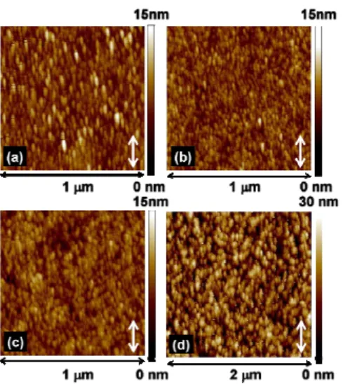
The LC/polymer films were imaged with an atomic force microscope (AFM) (Dimension 3100, Digital Instruments) at tapping mode at room temperature in air. Silicon nitride cantilevers (Nanosensors) with a resonant frequency of 260 kHz were used. The cantilevers were excited just below its resonant frequency. The apical radius of the cantilevers is about 15 nm. The AFM images of liquid crystal/polymer films with different LC concentrations are shown in Figs. 2(a)-2(d). As can be seen, the surface of the LC/polymer films shows elongated aggregation of polymer grains along the rubbing direction (indicated by arrows). The root-mean-square (RMS) roughness of the films surfaces is 1.5 nm at 10 wt% LC, 1.0 nm at 20 wt% LC, 1.5 nm at 30 wt% LC, and 5.0 nm at 40 wt% LC, respectively.
#101323 - $15.00 USD Received 9 Sep 2008; revised 10 Oct 2008; accepted 14 Oct 2008; published 16 Oct 2008
Fig. 2. AFM images of the LC/polymer composite film at (a) 10 wt% LC, (b) 20 wt% LC, (c) 30 wt% LC, and (d) 40 wt% LC.
To verify the LC directors anchored between polymer grains can be switched by the in-plane electric fields, we observed the LC/polymer films on the top of an IPS glass substrate (Fig. 1(a)) by using a polarizing optical microscope. The polarizer (P) and analyzer (A) are orthogonal to each other and the rubbing direction of the bottom IPS substrate is parallel to the transmission axis of the polarizer. As shown in Fig. 3, at V=0 Vrms the LC directors and
polymer grains tend to align along the direction of the transmission axis of the polarizer. However, the LC/polymer film still has a small light leakage because the LC directors and polymer grains are not perfectly aligned along the same direction. At 200 Vrms at f = 1 kHz,
the transmission of the LC/polymer film increases because of the birefringence effect induced by the LC reorientation. P A P A P A
Fig. 3. Microscopic photos taken from a polarizing microscope with crossed polarizers at 0 Vrms
and 200 Vrms. “P” indicates the transmission axis of the polarizer and “A” indicates the
transmission axis of the analyzer.
To observe the dynamic wettability of the LC/polymer films under in-plane electric fields, we carried out contact angle measurements using a CCD camera, as shown inFigs. 4(a) and 4(b). The CCD camera was looking at the water contact angle along the y-axis as Fig. 1 shows (or P-direction in Fig. 3). A 3 μl drop of de-ionized water was deposited on the LC/polymer films. The droplet covers over 500 electrode stripes. We applied 200 Vrms squared pulses (f =
1 kHz) to the LC/polymer film (with 60 wt% LC) for 600 ms.
#101323 - $15.00 USD Received 9 Sep 2008; revised 10 Oct 2008; accepted 14 Oct 2008; published 16 Oct 2008
(a) (b)
Fig. 4. (a)Contact angle measurement (Media 1), and (b) the image observing by CCD: the side view of water droplet on the top of LC/polymer film under 200 Vrms squared pulses (f = 1 kHz)
observed through a CCD camera (Media 2).
Figure 5 shows the measured results. We did measurements 6 times at different locations of each film and the averaged water contact angle changes periodically between 80.65o and 64.10o with periodically applied electric fields. The experimental error is ±2.5 degree. The contact angle fluctuation at the period of 0 Vrms and of 200 Vrms is a result of the elastic
bounce of the water droplet under voltage-on and voltage-off. The response time was defined as the total time duration of contact angle transition from the high degree to the low degree and then from the low degree to the high degree. It was found to be around 400 ms.
0 40 80 120 0 1 2 3 Time, second W a te r Co n tact An g le, de gr e e -200 0 200 400 600 800 A p p lie d V o lt a g e , V rm s 60 wt% LC 0 wt% LC IPS substrate Applied voltage
Fig. 5. Water contact angleas a function of time under a squared pulsed voltage (200 Vrms) with
600 ms time duration forthe LC/polymer composite films with 60 wt% LC and 0 wt% LC, and the IPS glass substrate.
In addition, the water contact angle on the LC/polymer film is electrically tunable. In Fig. 6, the difference between the maximal and minimal contact angles increases when we increase the amplitude of squared pulses of an in-plane electrical field with a fixed time duration at f = 1 kHz from 100 Vrms to 200 Vrms at 60 wt% LC. The threshold voltage is around 100 Vrms. The
total angle change is 2o at 100 Vrms (between 79o and 81o), 5o at 140 Vrms (between 75o and
80o), and 15o at 200 Vrms (between 65o and 80o).
#101323 - $15.00 USD Received 9 Sep 2008; revised 10 Oct 2008; accepted 14 Oct 2008; published 16 Oct 2008
0 20 40 60 80 100 0 0.8 1.6 2.4 3.2 Time, second W a te r C ont a c t A ngl e , de gre e 100Vrms 140Vrms 200Vrms 0 20 40 60 80 100 0 0.8 1.6 2.4 3.2 Time, second W a te r C ont a c t A ngl e , de gre e 100Vrms 140Vrms 200Vrms
Fig. 6. Water contact angle of the LC/polymer composite film with 60 wt% LC as a function of time under different squared pulsed voltage with 600 ms time duration. (f = 1 kHz)
To prove that the contact angle change results from the reorientation of the LC directors anchored among the polymer grains, we carried out the water contact experiments on pure polymer films without LC molecules. The water contact angle was found to be 57.63o. We also measured the water contact angle on the top of IPS glass substrate without LC/polymer film and it was found to be 54.45o. The measured water contact angle on the pure polymer films without LC molecules does not change with squared pulses of an in-plane electric field with a fixed time duration at f = 1 kHz, as shown in Fig. 5. Without LC, the surfaces, pure polymer film and IPS glass substrate, are more hydrophilic. Such surfaces are not suitable for electrostatic actuation. However, the water contact angle on the LC/polymer film with 60 wt% LC changes periodically with a periodically applied voltage even though the macroscopic surface is more hydrophilic. So we conclude that the orientation change of the LCs anchored between polymer grains in responding to the electric fields leads to the observed dynamic change of surface wettability. The electrostatic force can be neglected fortwo reasons: 1) the LC/polymer film is not operated in high-frequency-limit region (>10 kHz) in which dielectrophoretic (DEP) effect has influence on water droplet [18], and 2) the LC/polymer film is thick (about 12 μm), therefore, the electric field near the water-film surface is relatively weak to stretch the droplet using DEP, but it is strong enough to change LC orientations.
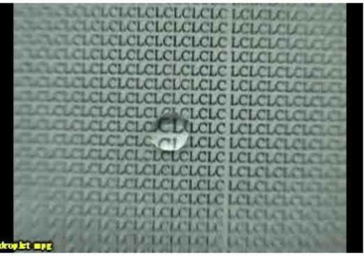
One application of LC/polymer film is the dynamic liquid lens, as Fig. 7 shows. A water droplet of ~6 μl was put on the top of the clear LC/polymer film and electrodes. The distance between the image and the substrate is 2 mm. The focal length changes periodically with the applied pulsed voltages. The measured focal length of the liquid lens is 4.2 mm at 0 Vrms and
5.3 mm at 200 Vrms. In Fig. 7, the contact angle change is along the direction of the in-plane
electric fields. In addition, the images inside the water droplet area have different magnification with applied electric field. This is because the contact angle change results in a change on the water droplet curvature which, in turn, leads to a focal length change.
#101323 - $15.00 USD Received 9 Sep 2008; revised 10 Oct 2008; accepted 14 Oct 2008; published 16 Oct 2008
Fig. 7. The top view of water droplet on a LC/polymer composite film under squared pulsed voltage (200 Vrms) with 600 ms time duration. (f = 1 kHz) A paper with printed images was put
right behind the glass substrate (Media 3).
5. Discussion
It is known that several factors can affect surface wettability, such as chemical properties of the materials, roughness, and chemical heterogeneity [19-21]. The effect of the roughness can be described by the Wenzel’s relationship [22]:
) cos( )
cos(θ1 =Rw⋅ θ2 , (1)
where Rw is the surface roughness factor, θ2 is the contact angle in the smooth surface and θ1
is the contact angle in a rough surface. Equation (1) describes the amplification of surface properties due to the surface roughness. The contact angle θ2 satisfies Young’s equation [23]:
LV SL SV
γ
γ
γ
θ
)
=
−
cos(
2 , (2)where
γ
represents the surface tension (i.e., energy per unit surface) of the interface, and S, L, and V indicate the phases of the solid, liquid and vapor. When a surface has the chemical heterogeneity and surface porosity, the contact angle (θ ) of modified Cassie’s equation can be expressed as [24]:)
cos(
)
cos(
)
cos(
θ
=
f
3⋅
θ
3+
f
4⋅
θ
4 , (3)where f3 and f4 are the fractions of the surface having inherent contact angles θ3and θ4. Here, f3 and f4 should satisfy: f3 + f4 =1. However, the water contact angle on the LC/polymer
composite film depends not only on the morphologies (both polymers and liquid crystals) but also on the orientation of LC directors which can be controlled by the applied electric fields. Thus, the contact angle (θ’) as a function of applied voltage (Vrms) in the LC/polymer
composite film should be:
)
cos(
))
(
cos(
)]
(
'
cos[
θ
V
rms=
f
lc⋅
θ
lcV
rms+
f
P⋅
θ
P , (4) LV rms L lc rms V lc rms lcV
V
V
γ
γ
γ
θ
(
))
(
)
(
)
cos(
=
,−
, , (5)where flc and fp are the fractions of LC and polymer grains for the inherent contact angles
θlc and θP, respectively. From Eq. (5), when the voltage is higher than the threshold voltage,
) ( ,L rms
lc V
γ is smaller thanγlc,L(0), because the tilts of the terminal groups of LC directors near the edge of the electrodes have a lower surface tension. By assumingγlc,V(Vrms)≈γlc,V(0), we #101323 - $15.00 USD Received 9 Sep 2008; revised 10 Oct 2008; accepted 14 Oct 2008; published 16 Oct 2008
can infer that θlc(Vrms)is smaller thanθlc(0)because cos(θlc(Vrms))>cos(θlc(0)). Therefore, the
surface wettability of the LC/polymer composite film is electrically switchable.
6. Conclusion
We have demonstrated electrically tunable wettability of an LC/polymer composite film, in which LC molecules are anchored among polymer grains. The LC reorientation among polymer grains at the LC/polymer composite film surfaces, which are switched by the electric field, is responsible for the observed tunable wettability of the LC/polymer composite film. The major advantages of LC/polymer composite film are threefold: 1) small Joule’s heating which is a common issue for DEP or electrowetting in water-based devices, 2) small hysterisis, and 3) low power consumption. The mechanism of DEP is to apply an inhomogeneous electric field to a dielectric liquid to generate a pulling force which changes the contact angle of the droplet. On the contrary, the wettability change of a LC/polymer composite film is because the molecular orientation anchored the polymer grains of the surface. The electrically switchable wettability of LC/polymer composite films has potential applications in liquid lens, windshield, polarizer-free displays, ink-jet printing, microfluidic devices, and lab-on-a-chip.
Acknowledgments
The authors are indebted to Prof. Shu-Hsia Chen of National Chiao Tung University (Taiwan) and Dr. Chih-Chung Cheng in ITRI (Taiwan) for discussions, Chi Mei Optoelectronics (Taiwan) for providing glass substrates, and Jiong-Kuan Li, Ting-Yu Chu and Chih-Ming Yang for technical assistance. This research was supported by the National Science Council (NSC) in Taiwan under the contract no. 96-2112-M-009-019-MY2.
#101323 - $15.00 USD Received 9 Sep 2008; revised 10 Oct 2008; accepted 14 Oct 2008; published 16 Oct 2008