I/Q Mismatch Using Pseudo-Offset Injection
in OFDM Systems
Ming-Fu Sun, Student Member, IEEE, Jui-Yuan Yu, and Terng-Yin Hsu, Member, IEEE
Abstract—This work presents a novel carrier frequency offset
(CFO) estimation algorithm, based on pseudo-CFO (P-CFO), to es-timate the CFO value under the conditions of I/Q mismatch for di-rect conversion structures with 2-dB gain error and 20-deg. phase error in frequency selective fading channels. To circumvent CFO with I/Q mismatch, the proposed P-CFO algorithm rotates three training symbols by adding extra frequency offset into the received sequence to improve CFO estimation. Simulation results indicate that the estimation error of the proposed method is about 0.3 ppm, which is lower than those of two-repeat preamble-based methods. Additionally, the proposed P-CFO algorithm is compatible with the conventional method, and is appropriate for SoC implemen-tation. The proposed scheme is implemented as part of an orthog-onal frequency-division multiplexing wireless receiver fabricated in a 0.13- m CMOS process with 3.3 0.4 mm2core area and 10-mW power consumption at 54-Mbits/s data rate.
Index Terms—Carrier frequency offset (CFO), direct
conver-sion, I/Q mismatch, orthogonal frequency-division multiplexing (OFDM).
I. INTRODUCTION
O
RTHOGONAL frequency-division multiplexing (OFDM) is a spectrally efficient signaling method for commu-nication over frequency-selective fading channels [1], [2]. OFDM has been utilized by many transmission systems, such as IEEE802.11a/g-based WLAN systems [3], [4], digital audio broadcasting (DAB) [5] and digital video broadcasting ter-restrial TV (DVB-T) [6]. Unfortunately, OFDM systems are sensitive to imperfect synchronization and nonideal front-end effects, leading to severe system performance degradation. Typically, OFDM is highly sensitive to carrier frequency offset (CFO), due to the Doppler shift of the radio frequency (RF) carrier, the mismatch of local oscillators (LOs) between the transmitter and the receiver, or phase noise of an oscillator. Frequency offset can introduce inter-carrier interference (ICI) in an OFDM receiver because of the loss of orthogonality between subcarriers, severely degrading the overall system performance without suitable correction. To avert performance degradation, OFDM systems have strict front-end specifications and expensive front-end implementations.Manuscript received June 30, 2005; revised June 20, 2007. This work was supported by the National Science Council of Taiwan, R.O.C., under Grant NSC94-2220-E-009-010 and NSC95-2221-E-009-093-MY2. This paper was recommended by Associate Editor G. Cauwenberghs.
The authors are with the Department of Computer Science, National Chiao-Tung University, Hsinchu 300, Taiwan, R.O.C. (e-mail: mfsun@csie. nctu.edu.tw; tyhsu@csie.nctu.edu.tw).
Digital Object Identifier 10.1109/TCSI.2008.916426
Recent investigations have concentrated on developing monolithic receiver architectures, particularly for low-cost technology [7]–[9]. Direct conversion architecture is one po-tential candidate for simple integration among various receiver architectures. However, direct conversion receivers also suffer from various impairments, including I/Q mismatch (IQ-M) of nonideal RF circuits, due to the gain and phase mismatch between in-phase (I) and quadrature-phase (Q). Specifically,
IQ-M arises when the phase and gain differences between I
and Q are not exactly 90 and 0 , respectively. IQ-M not only introduces unwanted image interference into the desired signal, but also restricts the accuracy of CFO estimation.
In practice, the simultaneous occurrence of CFO and IQ-M significantly degrades the system performance. Several schemes for OFDM systems have been proposed to handle frequency synchronization [10]–[17]. These schemes can be categorized as follows.
1) Data-aided (DA) methods, in which special training sym-bols are inserted into the transmitted data [10], [11]. 2) Nondata-aided (NDA) methods, in which the transmitted
data are used without any other additional information [12], [13].
3) Guard-interval-based (GIB) methods, in which the re-ceived data before the FFT and the inserted guard interval in the OFDM signal frame are used to handle synchro-nization [14], [15].
Some blind frequency estimators that rely on signal statistics have also been adopted to achieve frequency synchronization [16], [17]. Although these methods can work well under fre-quency offset, they do not consider the IQ-M. Therefore, in-troducing the IQ-M phenomenon into the system increases the estimation error. Tubbax et al. [18] have presented an algo-rithm that addresses both CFO and IQ-M. Their method can compensate for the mismatch with a gain error of up to 0.414 dB (10% gain error) and phase error of 10 . Fouladifard and Shafiee [19] proposed an iteration algorithm, which, however, does not guarantee the convergence condition of the estimation when considering the packet-based WLAN standards. The per-formance of their algorithm is verified in the range of 47 to 47 kHz, which is smaller than the standard requirement of 125 to 125 kHz. Gil et al. [20] developed a joint estimation of CFO, channel and IQ-M based on maximum likelihood (ML) criterion. Their proposed method has an accuracy that almost reaches the Cramer-Rao lower bound (CRLB), but is compu-tationally too expensive to be appropriate for hardware imple-mentation. Xing et al. [21] proposed a nonlinear least squares
Fig. 1. Block diagram of the referred receiver’s structure.
(NLS) frequency estimator under IQ-M which has a high com-putational complexity for NLS matrix operations. Additionally, the synchronization format (training symbols) of the proposed NLS scheme differs from the state of the art in WLAN standards such as IEEE 802.11 a/g. Therefore, NLS is incompatible with current standards.
To maintain and realize systems with imperfect RF distor-tions, this work focuses on improving the frequency offset esti-mation accuracy under the conditions of the joint impairments in both CFO and IQ-M. The proposed synchronization algorithm must also be suitable for application-specific integrated circuit (ASIC) implementation. This work develops a novel frequency offset estimation algorithm based on pseudo-CFO (P-CFO) to circumvent the large CFO estimation error generated by IQ-M. P-CFO applies only three training symbols, which are deliber-ately rotated by an additional frequency offset, to carry out fre-quency offset estimation even if IQ-M causes interference. Sim-ulation results indicate that the average estimation error of the proposed scheme is approximately 0.3 ppm, making a high per-formance receiver possible.
The rest of this paper is organized as follows. Section II de-scribes the OFDM system model in the presence of CFO and
IQ-M. Section III then introduces a novel algorithm for CFO
es-timation with IQ-M. Next, the simulation results and ASIC im-plementation are presented in Sections IV and V, respectively. Conclusions are finally drawn in Section VI.
II. SYSTEMMODEL
Fig. 1 schematically depicts a block diagram of a typical OFDM receiver in the presence of CFO and IQ-M. Based on the direct conversion architecture in [8], [19] and [22], the re-ceived signal after baseband processing with CFO and IQ-M is given by
(1) where and denote the representations of the re-ceived signal in the receiver, and additive white Gaussian noise (AWGN), respectively and and represent the gain error and phase error introduced from the front-end, respectively. The discrete-time representation of (1) after the received signal is digitized can be expressed as
(2)
Fig. 2. Preamble structure of the IEEE 802.11a/g.
where denotes the sampling period. Furthermore, (2) can be summarized as
(3) where denotes the complex conjugate operation. The re-ceived signal can thus be regarded as a gain, denoted by the signal gain (SG) , from the original signal added to the con-jugate multiplied by a delta value, called the mirror gain (MG)
. The signal and mirror gains are represented as follows.
(4) If neither gain nor phase error exist, then SG remains at unity, and MG decreases to zero. Significantly, the phase rotation is in-versed in the direction between the original signals and its con-jugate if the CFO is present. Hence, the conventional compen-sation algorithm, which simply multiplies the data by an expo-nential term, must be modified in accordance with the gain and phase errors. This work mainly focuses on extracting the CFO value with the IQ-M error.
III. ESTIMATION FORCARRIERFREQUENCYOFFSET
A. Conventional Algorithm
Many OFDM WLAN standards include two preambles for synchronization, namely short and long training symbols. Fig. 2 illustrates the preamble structure specified by the IEEE 802. 11a/g [3], [4]. The OFDM packet preamble consists of 10 iden-tical short training symbols , each containing 16 samples, and two identical long training symbols , 2, each containing 64 samples. The packet also contains a guard interval (GI2) with 32 samples. GI2 is the cyclic prefix for the long training symbol , i.e., it is the extra replica of the last 32 samples of . Short training symbols are typically applied for coarse estimation, while long training symbols are utilized for fine estimation.
All subcarriers in the first symbol of a system with CFO are rotated by the same angle to the same subcarriers in the second symbol. A basic strategy for computing the frequency offset is to employ two repeated training symbols. The following equa-tion concerning DA methods shows the CFO estimaequa-tion by two consecutive short training symbols in the time domain,
(5) where denotes the data samples of a short training symbol [2]. However, the estimation error increases when the gain or phase error at the receiver is not zero. To illustrate this effect, let
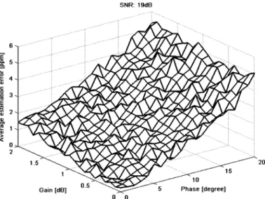
Fig. 3. CFO estimation by two-repeat preamble-based method under 19-dB SNR.
and represent two consecutive short pream-bles distorted by CFO and IQ-M, as shown below:
(6)
(7) To simplify the derivation, the noise distribution is ignored for the analysis. Because the short training symbols are periodic, , can be replaced by . The phase difference between two consecutive symbols can then be ex-pressed as
(8) where denotes the phase of its argument. The term rep-resents the interference term caused by CFO and IQ-M, given by
(9) Equation (9) indicates that a larger original CFO produces a larger estimation error. This effect always occurs if the scheme based on two identical symbols is applied. The effect is evident in Fig. 3, which illustrates the estimation of frequency offset versus the exact CFO value when the transmitting signal is dis-torted by noise, IQ-M and CFO. A modified method is devel-oped in next subsection to improve the estimation accuracy.
and are defined as three consecutive short preambles, which are distorted by CFO and IQ-M. The original frequency offset and the pseudo-frequency offset are assumed to be positive in the following mathematical derivations. The three preambles are then rotated by the pseudo-frequency offset. Therefore, the following equations hold:
(10)
(11)
(12) where denotes the pseudo-frequency offset. The extra P-CFO is used to resolve the transformation error resulting from noise disturbances, which is discussed later. The math-ematical derivation indicates the following (see Appendix for details)
(13)
(14) Equations (13) and (14) demonstrate that
(15) Since the sample time is 50 ns and the P-CFO is set to 30 ppm, is small and approximated as
. Accordingly, the following equation holds:
(16) From (16), (15) can be approximated as
Fig. 4. Inverse cosine function.
Consequently, the frequency offset can be computed from (17). The estimated frequency offset is given by
(18) The same method also indicates that
(19) From (19), the estimated frequency offset can be expressed as
(20) Therefore, the estimated of frequency offset can be averaged according to (18) and (20).
Fig. 4 shows the inverse cosine (arccosine) function for real element of in the domain [ , 1]. This figure indicates that the arccosine value should be zero if the original CFO value is 0ppm. However, there is a disadvantage of the cosine estimator . It is sensitive to even a small amount of noise dis-turbance when is relatively small. Therefore, the noise dis-turbance will have great effect on the CFO estimation and lead to transformation errors. The proposed method to solve this problem is to multiply the training sequence by an extra expo-nential term and get a larger CFO value. A larger CFO value prevents inverse cosine from being affected by noise disturbance and reduces the possibility of transformation errors accordingly. The maximum frequency error that can be estimated from a short training sequence is about 625 kHz, since the sample time is 50 ns, and the delay length is 16 [3]. The IEEE 802.11a standard specifies a maximum oscillator error of 20 ppm and a carrier frequency of approximately 5 GHz. Hence, the fre-quency difference between the transmitter and the receiver is
Fig. 5. Flowchart of the proposed P-CFO algorithm.
40 ppm, giving a maximum frequency offset of 200 kHz [3]. If the P-CFO is set to 50 ppm in the proposed algorithm, then the maximum frequency error is 450 kHz. Hence, the max-imum possible frequency error is well within the above range. For the IEEE 802.11g system, the carrier frequency may be ap-proximately 2.4 GHz, with 25 ppm (maximum) oscillator error. Therefore, the maximum frequency offset is about 120 kHz [4]. If the P-CFO is also set to 50 ppm, then the maximum fre-quency offset is 240 kHz. Although the proposed scheme uses an additional frequency offset to extract the frequency offset, it can meet the standard specification.
The frequency offset can be estimated similarly if the original CFO is negative. The sign of the CFO can be determined using the following equation:
(21) Fig. 5 shows the flowchart of the proposed P-CFO algorithm. The P-CFO estimator begins to compute the frequency offset with IQ-M after the frame detector detects a short training se-quence. The sign of the original CFO is first determined ac-cording to (21), so that the P-CFO shifter module can begin to work at the sign signal. The CFO calculation module then em-ploys the data from the P-CFO shifter module to compute the frequency offset. Since the arccosine value is positive, the esti-mated CFO from the CFO calculation module is multiplied by if the original CFO is negative. Finally, the P-CFO is sub-tracted or added from the estimated frequency offset in order to obtain the CFO. The proposed P-CFO algorithm can be summa-rized as follows:
1) If CFO , then rotate the received training symbols by an additional frequency offset based on (10)–(12); otherwise, rotate the symbols in the adverse direction.
2) Estimate the pseudo-frequency offset according to the pro-posed scheme based on (13)–(17) and (19).
3) If CFO , then subtract P-CFO from the estimated CFO as in (18) and (20); otherwise, multiply the estimated CFO by and add P-CFO.
4) Compensate for the frequency offset obtained in Step 3. After the long training symbols are successfully corrected for the effect of the frequency offset, the effect of IQ-M can be corrected by the available techniques [23].
IV. SIMULATION ANDPERFORMANCE
A typical OFDM system based on IEEE 802.11g for WLAN was adopted as a reference-design platform to evaluate the per-formance of the proposed algorithm. The parameters employed in the simulation platform were OFDM symbol length 64 and
cyclic prefix 16. IEEE 802.11g includes ten short training
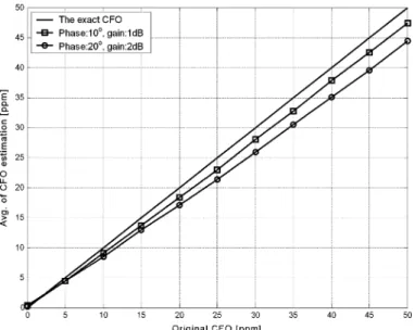
symbols for coarse estimation, and two long preambles for fine estimation. A satisfactory accuracy can usually be reached if sufficient data samples are applied to compute the estimate from the short training symbols. Consequently, the proposed method only uses short training symbols to measure the frequency offset under IQ-M conditions. In this experiment, the gain and phase errors were set to 2 dB and 20 , respectively. The CFO amount was simulated with values in the range of ppm to ppm at a carrier frequency of 2.4 GHz, and the additional P-CFO was set to 30 ppm. Table I lists the simulation parameters for frequency-selective fading channels. For a fair comparison, the two-repeat preamble-based scheme also used three training symbols to estimate the CFO value. Fig. 6 shows the estimation of frequency offset versus the exact CFO value, based on the simulation parameters in Table I. Simulation results indicate that the proposed algorithm can estimate the frequency offset more accurately than the two-repeat preamble-based scheme.
Figs. 7 and 8 illustrate the estimation errors of the frequency offset estimation under different IQ-M values, where the fre-quency offset is 50 ppm. These figures clearly demonstrate that the estimation error of the conventional (two-repeat preamble-based) method increases as IQ-M increases. The conventional method is thus insufficiently robust under different IQ-M con-ditions. Fig. 8 clearly shows that the estimation error of the pro-posed method is independent of IQ-M, and provides smaller errors than the two-repeat preamble-based approaches. Pollet
et al. [24] found that setting the maximum tolerable frequency
offset to 1% of the subcarrier spacing keeps the degradation as low as about 0.1 dB. For instance, the oscillator accuracy must be about 3 kHz or 1.25 ppm for an OFDM system at a carrier frequency of 2.4 GHz and a subcarrier spacing of 312.5 kHz. Consequently, the proposed algorithm is accurate in estimating
Fig. 6. Frequency offset estimation.
Fig. 7. CFO estimation by the two-repeat preamble-based method.
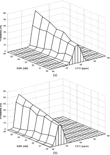
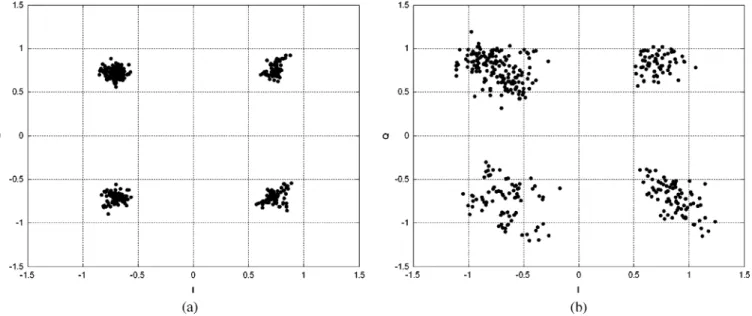
Fig. 9. PDF of 50ppm CFO: (a) P-CFO algorithm (b) Two-repeat preamble-based method.
the frequency offset with IQ-M, preventing significant perfor-mance loss.
The estimated frequency offset under IQ-M can be charac-terized by a Gaussian probability density function (PDF), as shown in Fig. 9(a) and (b). Fig. 9(a) clearly shows that the mean of the proposed P-CFO algorithm was close that of the orig-inal CFO. However, the two-repeat preamble based method, as shown in Fig. 9(b), always had bias. These figures indicate that the proposed P-CFO algorithm allows the correct CFO to be ex-tracted under IQ-M conditions. Fig. 10 shows the mean square error (MSE) of frequency estimation versus signal-to-noise ratio (SNR) under different IQ-M conditions. Fig. 10 indicates that for almost the entire SNR range, the P-CFO algorithm under the condition of 2-dB gain error and 20 phase error performed better than conventional methods under the same condition or moderate IQ-M scenario, i.e., 1-dB gain error and 10 phase error. The P-CFO algorithm thus has better estimation accu-racy under IQ-M than conventional methods. Since there are some approximations in the derivation, the MSE of the P-CFO algorithm is slightly weaker than the two-repeat preamble-based method under ideal I/Q. Table II summarizes the required SNR under 10 MSE. Fig. 11 indicates that the proposed method has a smaller estimation error than the two-repeat preamble-based method in the range 50 ppm to 50 ppm. In floating-point
Fig. 10. Mean square error (MSE) of frequency estimation versus SNR under different I/Q imbalance conditions with 50 ppm CFO.
TABLE II REQUIREDSNR
Fig. 11. Average of the estimation error.
simulations, the proposed algorithm with a deterministic CFO has the same performance as that with a randomly generated CFO. However, fixed-point simulations have some performance degradation, which is still lower than that of the two-repeat pre-amble-based scheme. Since the proposed scheme significantly reduces the impact of CFO, it can utilize IQ-M compensation more easily than conventional methods [23].
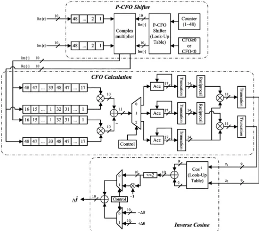
Fig. 12. Hardware architecture of the P-CFO algorithm.
V. IMPLEMENTATIONHELPFULHINTS
A. Design Methodology
The frequency estimator was implemented as a bit-and-cycle-true Matlab model, where performance simulations and algorithmic exploration were performed. In the hardware de-sign flows, the fixed-point function blocks replace the floating function blocks in the Matlab model to specify a suitable signal wordlength. The Verilog source code was generated from the fixed-point Matlab model after determining the architecture with fixed-point simulations. Additionally, a simulation en-vironment was created to verify the frequency estimator by performing an automatic comparison check on the internal signals and on the output signals between the gate-level netlists and the fixed-point Matlab model. Layout versus schematic (LVS) and design rule checking (DRC) were performed to verify the layout following its creation by the auto place and routing (APR) tools. Finally, post-layout simulations were also executed to verify the proposed design.
B. Architecture of P-CFO Algorithm
Fig. 12 illustrates the architecture of the P-CFO algorithm. The P-CFO scheme contains three main parts, P-CFO shifter, CFO calculation and inverse cosine. The P-CFO shifter module begins to work when the training symbols arrive. The P-CFO shifter module rotates the received training symbols by the pseudo-frequency offset. As shown in Fig. 12, the rotation is achieved by a look-up table and a complex multiplier. The direct implementation of the complex multiplier was modified
TABLE III COMPLEXMULTIPLIER
to lower its complexity and hardware cost. Table III clearly indicates that the direct implementation employs four multi-pliers and two adders. However, the modified implementation only requires three multipliers and five adders to lower the hardware cost (if the wordlength is sufficiently long). The CFO calculation module starts to perform CFO estimation based on the proposed algorithm when the P-CFO shifter module finishes the rotation. Fig. 12 shows that the estimation is realized by six multipliers (four for multiplication and two for division) and four adders. The output of CFO calculation module is transmitted to the inverse cosine module after the CFO is calculated. The inverse cosine module determines the angle of the correlation calculated from the CFO calculation module, and then adds or subtracts the pseudo-frequency offset to extract the final CFO. Table IV lists the synthesis results of the proposed P-CFO algorithm. Based on the proposed architecture, a test chip compliant to OFDM receiver was implemented in a standard 0.13- m CMOS technology with 10 mW power consumption, and housed in a 144-pin CQFP package. P-CFO part occupies approximately 34K gates, which
TABLE IV
COMPLEXITY(GATECOUNT)OFP-CFO
Fig. 13. Chip micrograph.
TABLE V CHIPSUMMARY
are roughly equal to 0.23 mm in 0.13- m CMOS technology. The chip micrograph is shown in Fig. 13, and its parameters are listed in Table V.
C. Verification Platform
A verification platform was constructed to measure the performance of both the proposed method and the conventional method (two-repeat preamble-based method), as shown in Fig. 14. The design was directly mapped onto the FPGA chips (Xilinx XtremeDSP, Virtex-II) with on-board 14-bit digital to analog converters (DACs) to transform the digital data into analog signals. Then the signals were transmitted by in-house RF front-end. After down-converting RF signals to baseband at RX part, the analog signals are fed to 14-bit analog to digital converters (ADCs). The received data from ADCs was processed to calculate the CFO value using both the proposed method and the conventional method. In the meantime, the received data from ADCs was also applied to the chip testing, which was performed to verify the full functionality of the
Fig. 14. Photo of platform.
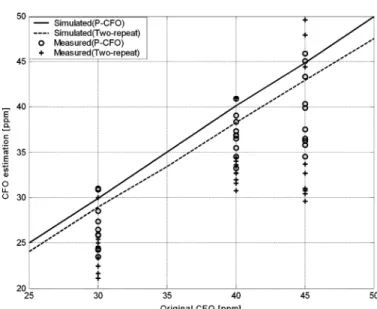
Fig. 15. Estimated CFO of measurement versus simulation.
chip using Agilent 93000 SOC Test System. After the CFO estimation and chip testing processes, the results were collected to evaluate the performance of both the proposed method and the conventional method.
The observed gain error and phase error are 0.9 dB and , respectively. Fig. 15 shows both the measured and sim-ulated CFO value. It indicates that the measured performance is a little worse than simulations since there are other spurious effects, noise, and nonlinearities in the front-end. Although there is degradation in measured performance, the proposed method is still more accuracy. Fig. 16 shows the baseband constellation for a quadrature phase-shift keying (QPSK) mod-ulation scheme. The rms error vector magnitude (EVM) for the proposed method is 7.4% [Fig. 16(a)], while the EVM for the two-repeat preamble-based is 24.4% [Fig. 16(b)]. So the proposed solution is more robust than the conventional method under IQ-M conditions.
VI. CONCLUSION
This work has proposed a novel algorithm to estimate the fre-quency offset under the conditions of IQ-M in direct conver-sion OFDM receivers. The proposed algorithm can adopt three training symbols to estimate the frequency offset from ppm to ppm under a 2.4 GHz carrier frequency with 2-dB gain error and 20 phase error in multipath environments. Simula-tion results indicate that the average estimaSimula-tion error of the pro-posed P-CFO algorithm can fulfill many system requirements,
Fig. 16. Measurements of QPSK constellation. (a) P-CFO method. (b) Two-repeat preamble-based method.
preventing obvious performance loss under different IQ-M con-ditions. The proposed design is implemented in an ASIC with 3.3 0.4 mm core area and 10 mW power dissipation at 54 Mbits/s data rate. Hence, the proposed algorithm can enhance the performance of wireless OFDM systems, enabling small low-cost systems to be achieved.
APPENDIX
DERIVATION OF(13), (14) To simplify the notation, let
Using (10)–(12), we have
(A.1)
(A.2)
Furthermore, can be
ex-pressed as
(A.3) Since the sample time is 50 ns and the P-CFO is set to 30 ppm, can be approximated as (the value of
is )
Consequently, (A.3) can be simplified to
(A.5) It is clear to know that (A.5) is the same as (13). Thus, (14) can also be derived by the same technique described above.
ACKNOWLEDGMENT
The authors gratefully acknowledge the constructive com-ments provided by the anonymous reviewers which have added much to the clarity of the paper. They also want to thank the members of the ISIP laboratory of Computer Science, National Chiao-Tung University, Taiwan, R.O.C., for many helpful sug-gestions in chip design and testing.
REFERENCES
[1] R. V. Nee and R. Parsed, OFDM for Wireless Multimedia
Communi-cation. Natick, MA: Artech House, 2000.
[2] J. Heiskala and J. Terry, OFDM Wireless LANs: A Theoretical and
Practical Guide. Indianapolis, IN: Sams, 2001.
[3] Wireless LAN Medium Access Control (MAC) and Physical Layer
(PHY) Specifications, , 1999, IEEE Std 802.11a.
[4] Wireless LAN Medium Access Control (MAC) and Physical Layer
(PHY) Specifications, , 2003, IEEE Std 802.11g.
[5] Radio Broadcasting Systems: Digital Audio Broadcasting to Mobile,
Portable and Fixed Receivers, ETSI standard 300 401, Feb. 1, 1995.
[6] Digital Video Broadcasting: Framing Structure, Channel Coding, and
Modulation for Digital Terrestrial Television, ETSI standard 300 421,
Aug. 1, 1997.
[7] B. Razavi, RF Microelectronics. Upper Saddle River, NJ: Prentice-Hall, 1998.
[8] B. Razavi, “Design consideration for direct-conversion receivers,”
IEEE Trans. Circuit Syst. II, Analog Digit. Signal Process., vol. 44,
no. 6, pp. 428–435, Jun. 1997.
[9] A. A. Abidi, “Direct-conversion radio transceivers for digital commu-nications,” IEEE J. Solid-State Circuits, vol. 30, no. 12, pp. 1399–1410, Dec. 1995.
[10] P. H. Moose, “A technique for orthogonal frequency division multi-plexing frequency offset correction,” IEEE Trans. Commun., vol. 42, no. 10, pp. 2908–2914, Oct. 1994.
[11] F. Classen and Myer, “Frequency synchronization algorithms for OFDM systems suitable for communication over frequency selective fading channels,” in Proc. IEEE Veh. Technol. Conf., Stockholm, Sweden, Jun. 8–10, 1994, pp. 1655–1659.
[12] F. Daffara and A. Chouly, “Maximum likelihood frequency detec-tors for orthogonal multicarrier systems,” in Proc. IEEE Int. Conf.
Commun., Geneva, Switzerland, May 23–26, 1993, pp. 766–771.
[13] M. Luise and R. Reggiannini, “Carrier frequency acquisition and tracking for OFDM systems,” IEEE Trans. Commun., vol. 44, no. 11, pp. 1590–1598, Nov. 1996.
[14] F. Daffara and O. Adami, “A new frequency detector for orthogonal multicarrier transmission techniques,” in Proc. IEEE Veh. Technol.
Conf., Chicago, IL, Jul. 25–28, 1995, pp. 804–809.
[15] M. Okada, S. Hara, S. Komaki, and N. Morinaga, “Optimum synchro-nization of orthogonal multi-carrier modulated signals,” in Proc. IEEE
PIMRC, Taipei, Taiwan, Oct. 15– 18, 1996, pp. 863–867.
[16] B. Chen and H. Wang, “Blind estimation of OFDM carrier frequency offset via oversampling,” IEEE Trans. Signal Process., vol. 52, no. 7, pp. 2047–2057, Jul. 2004.
[17] M. Luisem, M. Marselli, and R. Reggiannini, “Low-complexity blind carrier frequency recovery for OFDM signals over frequency-selective radio channels,” IEEE Trans. Commun., vol. 50, no. 7, pp. 1182–1188, Jul. 2002.
[18] J. Tubbax, A. Fort, L. Van der Perre, S. Donnay, M. Engels, and H. De Man, “Joint compensation of IQ imbalance and frequency offset in OFDM systems,” in Proc. GLOBECOM, Dec. 1–5, 2003, vol. 4, pp. 2365–2369.
[19] S. Fouladifard and H. Shafiee, “Frequency offset estimation in OFDM systems in the presence of IQ imbalance,” in Proc. IEEE Int. Conf.
Commun., May 11–15, 2003, vol. 3, pp. 2071–2075.
[20] G. T. Gil, I. H. Sohn, J. K. Park, and Y. H. Lee, “Joint ML estimation of carrier frequency, channel, I/Q mismatch, and DC offset in com-munication receivers,” IEEE Trans. Veh. Technol., vol. 54, no. 1, pp. 338–349, Jan. 2005.
[21] G. Xing, M. Shen, and H. Liu, “Frequency offset and I/Q imbalance compensation for direct-conversion receivers,” IEEE Trans. Wireless
Commun., vol. 4, no. 2, pp. 673–680, Mar. 2005.
[22] P. Zhang, T. Nguyen, C. Lam, D. Gambetta, T. Soorapanth, B. Cheng, S. Hart, I. Sever, T. Bourdi, A. Tham, and B. Razavi, “A 5-GHz direct conversion CMOS transceiver,” IEEE J. Solid-State Circuits, vol. 38, no. 12, pp. 2232–2238, Dec. 2003.
[23] J. Y. Yu, M. F. Sun, T. Y. Hsu, and C. Y. Lee, “A novel technique for
I/Q imbalance and CFO compensation in OFDM systems,” in Proc. IEEE ISCAS, Kobe, Japan, May 2005, pp. 6030–6033.
[24] T. Pollet, M. van Bladel, and M. Moeneclaey, “BER sensitivity of OFDM systems to carrier frequency offset and wiener phase noise,”
IEEE Trans. Commun., vol. 43, pp. 191–193, Apr. 1995.
Ming-Fu Sun (S’05) was born in Taipei, Taiwan,
R.O.C., in 1981. He received the B.S. and M.S. degrees in computer science and information en-gineering from National Chiao-Tung University, Hsinchu, Taiwan, R.O.C., in 2003 and 2005, respec-tively.
In 2005, he joined the Institute of Computer Science of National Chiao-Tung University, where he is currently working toward the Ph.D. degree. During 2006, he was a Lecturer in the Department of Electronics Engineering, Ming Hsin University of Science and Technology. His major research interests include signal processing for wireless communications, multiple-input multiple-output orthogonal frequency-division multiplexing systems, and associated VLSI architectures.
Jui-Yuan Yu was born in Taipei, Taiwan, R.O.C.,
1979. He received the B.S. degree in electronics engineering from National Chiao-Tung University, Hsinchu, Taiwan, R.O.C., in 2002. He is currently working toward the Ph.D. degree in electronics engineering in the same department.
His research interests include VLSI architec-ture, low-power SoC, and wireless communication systems, especially in OFDM-based baseband transceiver for high-speed WLAN, ultra-wide-band (UWB) systems, and low-power WBAN systems.
Terng-Yin Hsu (M’07) received the B.S. and M.S.
degrees from Feng Chia University, Taichung, Taiwan, R.O.C., in 1993 and 1995, respectively, and the Ph.D. degree from National Chiao-Tung University, Hsinchu, Taiwan, R.O.C., in 1999, all in electronic engineering.
In 2003, he joined Department. of Computer Science, National Chiao-Tung University, where he is currently an Assistant Professor. His research interests mainly include VLSI architectures, wire-less communications, multi-spec transmissions, high-speed networking, analog-like digital circuits, system-on-chip (SoC) design technology, and related ASIC designs.
![Fig. 4 shows the inverse cosine (arccosine) function for real element of in the domain [ , 1]](https://thumb-ap.123doks.com/thumbv2/9libinfo/7617296.130981/4.891.61.434.94.389/fig-shows-inverse-cosine-arccosine-function-element-domain.webp)