Analysis of die design for the stamping of a bathtub
Fuh-Kuo Chen *, Bai-Hong Chiang
Department of Mechanical Engineering, National Taiwan Uni6ersity, Taipei, Taiwan, ROC
Received 2 October 1996
Abstract
The die design for the stamping of the base of an enameled bathtub was performed using the three-dimensional finite-element method. The difficulty encountered in the stamping process is the occurrence of both fracture and wrinkling. To facilitate the analysis, a series of experiments was conducted to obtain the material properties and the forming-limit diagram for the enamel steel used for the actual production and for the finite-element simulations, the latter being first performed to analyze the metal-flow causing the wrinkles on the draw-wall. The strain distributions obtained from the finite-element simulations were also used in conjunction with the forming-limit diagram to predict the onset of fracture. In addition, the effects of blank-holder pressure and friction on the occurrence of fracture and wrinkling were investigated. An optimum drawbead distribution on the die face was then determined, according to the finite-element analysis, to avoid the formation of both fracture and wrinkles. © 1997 Elsevier Science S.A.
Keywords:Stamping die design; Bathtub; Three-dimensional finite-element method; Equivalent drawbead
1. Introduction
The stamping of the base of an enameled bathtub constitutes a deep-drawing process due to the inherent geometry of the part, as shown in Fig. 1. The stamped part, which is used as the base for the subsequent enameling process, is made of enamel steel and is to be formed by a single drawing process to avoid drawing marks caused by a multi-stamping process. Also, the flange width around the cavity of the final shape should be greater than 100 mm, required by the part design. The efforts focused on the die design for the stamping of such a deeply-drawn part are mainly to avoid major defects such as wrinkling and fracture. A successful die design generally results from an accurate prediction of the metal-flow during the forming process, which latter relies mostly on the experience and know-how of engi-neers in actual practice. However, since the two-dimen-sional finite-element method was applied to the analysis of metal-forming processes in the 1980s [1], metal-flow has been able to be predicted easily from computer simulations. In the early 1990s, the successful
applica-tion of the three-dimensional dynamic/explicit finite-ele-ment method to sheet-metal forming process made the prediction of metal flow even more accurate [2,3]. Since then, finite-element analysis has been adopted widely to simulate actual die try-outs and has become a very powerful tool and of considerable help to the die de-signer.
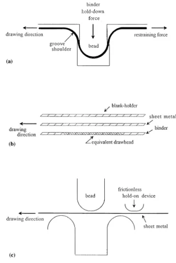
In the present study, the die design for the stamping of a bathtub, as shown in Fig. 1, was investigated using three-dimensional dynamic/explicit finite-element analy-sis. Since the part is drawn to the desired shape by only one operation, the shape of the die cavity must possess the tub geometry and leave the major concerns of die design on the sheet-blank geometry and the die face shape, i.e. the flange area of the bathtub. The die face design involves the geometry and the location of the drawbead, which is a small bead on the blank holder matched by a groove on the die surface, as shown in Fig. 2(a), the function of the drawbead being to control the metal flow from the blank holder to the die cavity. In the finite-element simulations, the sheet-metal that is pulled through the drawbead during drawing must be modeled by very small elements to reflect the effect of the bending deformation of the sheet metal around the drawbead, resulting in a large amount of computation
* Corresponding author. Fax: + 886 2 3631755; e-mail: [email protected]
0924-0136/97/$17.00 © 1997 Elsevier Science S.A. All rights reserved. PIIS 0 9 2 4 - 0 1 3 6 ( 9 7 ) 0 0 2 0 5 - 7
time. In order to cope with this dilemma, an equivalent drawbead model, which will be discussed later in this paper, was developed [4] to replace the full-scale physi-cal modeling of the drawbead in the finite-element simulations. With the equivalent drawbead model used, reasonably large elements for the sheet metal passing through the drawbead can be assigned and in conse-quence, a huge saving of computation time can be achieved.
In order to facilitate the die-design analysis, tensile tests were performed to obtain the stress – strain rela-tionships for the sheet-metal used in the finite-element simulations. A forming-limit diagram (FLD) for the sheet metal was also constructed by experiments, the forming limit diagram being used in conjunction with the finite-element results to predict the failure of the sheet metal in the stamping process.
In the present study, the 3-D finite-element simula-tions were first performed to analyze the metal flow causing wrinkles in the draw wall. In order to eliminate wrinkles without introducing fracture, the effects of the blank-holder pressure, friction and the distribution of the drawbead were investigated also. The strain distri-butions for various stamping conditions as well as the forming-limit diagram were established for designing an
Fig. 2. Drawbead configurations: (a) Actual drawbead; (b) equivalent drawbead model; and (c) finite-element model.
Fig. 1. Finite-element meshes.
optimum set of stamping dies. The die design obtained from the finite-element analysis was validated by the production part.
All of the simulations performed in the present study were run on an HP735 work-station with the use of the finite-element program PAM –STAMP.
2. Mechanical-properties tests
The bathtub is made of anamel steel (SPP) of 1.6 mm thickness. The tensile tests and the necessary experi-ments for constructing the forming-limit diagram were conducted, the results being described as follows.
2.1. Tensile tests
An accurate finite-element analysis of complex shapes of stamped metal components requires the ac-tual stress – strain relationship of the sheet metal as part of the input data. In the present study, the sheet specimens were prepared according to ASTM stan-dards. The specimens were cut along planes coinciding with the rolling direction (0°) and at angles of 45 and
90° to the rolling direction. The cut edges were polished to avoid fracture occurring at an undesired location of the specimen. The average flow stress, s¯, calculated from the equation s¯=(s0+ 2s45+s90)/4, for each measured true strain, as plotted in Fig. 3, was used for the finite-element simulations, where s0, s45 and s90,
are the flow stresses obtained from the specimens cut along the rolling direction and at 45 and 90° to the rolling direction, respectively. As seen in Fig. 3, the yield stress of the enamel steel is 160 MPa, which is as soft as for drawing-quality steel.
2.2. Forming-limit diagram
Since Keeler [5] introduced the concept of the form-ing-limit diagram (FLD) in 1963, it has been a widely accepted criterion for fracture prediction in sheet-metal forming. To determine a FLD, stretching tests were performed for sheet-metal specimens of different widths. The specimens were first electrochemically-etched with circular grids that would be deformed into ellipses after being stretched. The engineering strains measured in the directions along the major- and minor-axes of the ellipse are termed the major strain and minor strain, respectively.
In the present study, rectangular specimens having the same length of 140 mm, but with different widths ranging from 20 to 140 mm at increments of 20 mm, were tested. The sheet metal was cut along three orien-tations to the rolling direction, i.e. 0, 45 and 90°, for each size of specimen. During the tests, sheet-metal specimens clamped at the periphery were stretched to failure over a 78 mm diameter hemispherical punch. The engineering major- and minor-strains measured in the location closest to the fracture for each specimen were recorded. In order to use the forming-limit
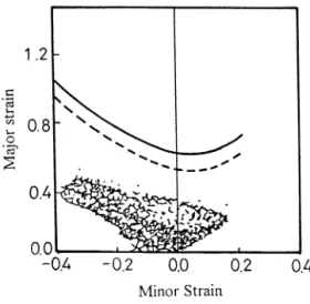
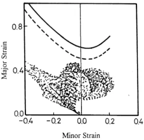
dia-Fig. 4. Forming limit curves.
gram as a fracture criterion for the finite-element analy-sis, the engineering major- and minor-strains were converted into the true major- and minor-strains ac-cording to the relationshipe=ln(1+e), where e and e were the true strain and the engineering strain, respec-tively. The true major- and minor-strains were plotted against one another with the major strain as the ordi-nate; and for a conservative prediction, the curve envel-oping the lowest points was defined as the forming limit, as shown in Fig. 4, and was termed the failure curve. In practice, the failure curve moved down by 10% was used as the design curve. Since the major- and minor-strains of the deformed ellipses coincide with the principal strains, which can be easily obtained from the simulation results, the FLD is a very useful criterion for the prediction of the occurrence of fracture, based on the finite-element analysis.
3. The equivalent drawbead model
When the punch draws the sheet metal into the die cavity after the blank-holder closure, the sheet metal passing through the drawbead is subjected to bending and subsequent unbending around the entry groove shoulder and a repeated sequence at the bead and the exit groove shoulder, as shown in Fig. 2(a). These bending and unbending deformations together with the frictional force account for the drawbead restraining force.
Since the size of a drawbead is usually very small compared to the remaining portion of the die surface, the sheet metal that is pulled through the drawbeads during drawing must be modeled by very small ele-ments to reflect the effect of the bending deformation of the sheet metal around the drawbeads. A finite-element
model with such small elements results in an increase in the number of elements and contact segments and a decrease in the minimum time step and in consequence, proves to be uneconomical in terms of computation time. In the equivalent drawbead model, the actual drawbead is replaced by its projection onto the binder surface, i.e. a flat surface which has the same width as that of the actual drawbead and a regular mesh is constructed for the flat surface, as shown by the shaded area in Fig. 2(b). The restraining force exerted by the actual drawbead is assigned distributedly to the nodes in the regular mesh of the equivalent drawbead follow-ing the virtual-work principle. The assigned restrainfollow-ing forces are then assumed to act on the sheet metal which moves through these nodes. Hence, the sheet metal passing through the equivalent drawbead model is sub-jected to the same restraining force as that exerted by the actual drawbead. The use of an equivalent draw-bead model eliminates the need for using an extremely fine mesh. Therefore, an accurate estimation of the restraining force produced by the actual drawbead is essential for setting up the equivalent drawbead model. The restraining force produced by the actual draw-bead can be obtained by the finite-element simulations with the use of the simple model shown in Fig. 2(c) [6]. In this model the bead first moves down to the blank-holder position at which the center of the bead has the same height as the center of the grooves. The position of the leading edge of the sheet metal is maintained by assigning a fixed-end boundary condition. The sheet metal is then pulled through the drawbead with an assigned velocity. The calculated restraining force is normalized by the width of strip used in the simulation so that the program can be used to estimate the total force exerted by drawbeads having different lengths. In the present study, the restraining forces were used in the finite-element analysis for the drawbead design without considering the actual drawbead shapes. The actual drawbead, which can be derived conversely from the restraining force, is required only when the opti-mum die design is achieved.
4. Finite-element model
The tooling geometries generated by a CAD program for the initial die design were provided by the die maker. The CAD file was first modified to eliminate the overlaps and gaps existing between patches, so that the finite-element mesh could be constructed. Since the tooling geometries are usually very complex, the gener-ation of the finite-element mesh requires the help of a CAD program. In the present study, the mesh systems for the finite element simulations were generated with the use of the CAD program STRIM 100.
In the finite-element simulations, the tooling is con-sidered to be rigid, and the corresponding meshes are used only to define the tooling geometries and are not involved in the deformation calculations. Hence, it is very important to use a sufficiently fine mesh to best represent the tooling geometries. On the other hand, the computation time for the simulation of a stamping process using the explicit finite-element method is mostly governed by the size of the minimum element used in the mesh of the sheet blank, since the time step for integration is limited by a critical time increment DT=L/c, where L is the characteristic length of the minimum element in the mesh and c is the wave speed traveling in the sheet metal. Therefore, the element size is desired to be as large as possible in a mesh system for the sheet metal to be analyzed.
In the present study, the four-node shell element was used to construct the meshes for both the booling and the sheet blank used in the initial die design, as shown in Fig. 1, the numbers of elements and nodes used in each entity are listed in Table 1.
In the simulation, the sheet metal was placed on the blank-holder and the die moved down to clamp the sheet metal against the blank-holder, so that the shape of the binder-wrap was formed. Next, the punch was moved up to draw the sheet metal to the desired shape with a total stroke of 400 mm. The stress – strain rela-tionship as given in Fig. 3 was used in the finite-element simulations. To facilitate the simulation, the punch speed is set to 10 m s− 1for all simulations. The other
process parameters, such as the friction coefficient and blank-holder pressure, are set differently for the differ-ent stamping conditions.
5. Results and discussion
An optimum sheet-blank shape determined by the finite-element analysis was used for all die designs. The four corners of this optimum sheet blank were cut off, as shown in Fig. 1, to facilitate metal flow at the edges [7]. To limit the length of this paper, the procedures through which the dimensions of the optimum sheet blank was obtained will not be discussed. The shape of die cavity conforming to the geometry of the bathtub
Table 1
Number of elements and nodes
Element Mesh Node 4984 Die 4580 Punch 3356 3037 999 Blank-holder 981 Blank 9604 9801 18 417 18 925 Total
Fig. 5. Simulated shape for the initial die design.
Fig. 6. Strain distributions in the simulated shape.
was also maintained as the same for all of the die face designs since the bathtub was drawn to the desired shape in one operation. In consequence, the die design was focused only on the die face. In order to analyze the metal flow, a flat surface without a drawbead was used as the initial design for the die face. The analysis of the modified die design was then performed accord-ing to the pattern of metal flow obtained from the finite-element simulations. In addition to the die face design, finite-element simulations were also conducted to study the effect of the process parameters such as friction and blank-holder pressure, on the formability of the stamping process. The simulation results are summarized and discussed as follows.
5.1. Initial die face design
A clamping force of 2.254 MN exerted by the blank holder and a coefficient of friction of 0.1 were assumed for the initial die design, the final shape that results from which design being shown in Fig. 5. As seen in this figure, significant metal flow occurs in the middle flange resulting in a relatively small flange width, less than the required width of 100 mm. Moreover, wrinkles also appear on the draw wall, as shown in Fig. 5. The major- and minor-strain distributions as well as the forming-limit diagram are shown in Fig. 6. It is seen clearly that the final shape is free from fracture, but the small flange width and the presence of wrinkles are not permitted in the actual product so that the die face must therefore be modified. Both the narrowness of the flange and the formation of wrinkles resulted from a significant metal flow at these areas. One of the efficient methods of restraining metal flow in stamping-die de-sign is to add drawbeads on the die face. However, the determination of the geometry and location of the drawbead requires the analysis of metal flow during the drawing operation.
Comparison of the initial and an intermediate step mesh systems, as shown in Fig. 7, reveals that the metal is drawn into the die cavity directly from point C to point D at the short flange and that the wrinkle area (A) results from the metal flow in the 6 direction, as
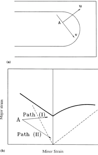
shown. It is obvious that a drawbead must be added perpendicular to the line C – D to restrain the metal flow in the small flange. As for the restraint of the metal flow causing the wrinkles, consideration of the forming-limit diagram may be helpful. Fig. 8(a) shows that the wrinkle area is under the deformation pattern of the draw mode, i.e. the major strain is in tension and the minor strain is in compression. The major- and mior-strain directions at point A coincide with the u and 6 directions, respectively, as shown in Fig. 8(a). Since wrinkles are induced by compression, a decrease in the magnitude of the minor strain is necessary to eliminate them. This can be achieved by moving point A to the right of the forming-limit diagram either through path (I) or path (II), as shown in Fig. 8(b). In path (I), the metal flow in the 6 direction is restrained so that the magnitude of the major strain is kept unchanged whilst that of the minor strain is decreased. On the other hand, the metal flow in the u direction prevails in path (II), resulting in a decrease of the major strain and an increase of the minor strain. The main purpose in both cases is to decrease the compressive stress in the wrinkle area. In the actual stamping opera-tion, there are several possible steps to obtain the metal flow described in paths (I) and (II), such as an increase in the blank-holder pressure, an increase in friction at the interface between the blank and the die and the addition of drawbeads on the die face.
Fig. 8. Forming-limit diagram analysis: (a) Directions of the major-and minor-axes; major-and (b) paths to increase the minor strain.
Fig. 9. Strain distributions for different processes: (a) Increase of the blank-holder pressure; and (b) increase of friction.
5.2. Drawbead design
In order to eliminate the wrinkles without causing the problem of fracture, an optimum design of the size and the location of drawbeads on the die face proves itself as an efficient method to achieve this goal. Fol-lowing the observation of the metal flow obtained from the finite-element results, the drawbead was divided into four portions, as shown in Fig. 10, denoted db1, db2, db3 and db4, so that a more precise control of metal flow could be achieved. In the finite-element simulations, the equivalent drawbead model was used and the restraining force produced by the actual draw-bead was assumed, instead of considering the actual geometry of the drawbead. The advantage of using the equivalent drawbead model is two-fold: One is the large saving of computation time, and the other is that there is no need to deal with the actual drawbead shapes until Finite-element simulations were performed to study
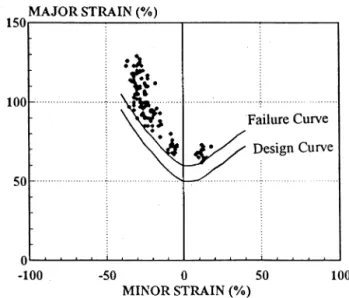
the effect of the blank-holder pressure on the occur-rence of wrinkles. The wrinkles disappear when the blank-holder pressure is increased from 2.254 to 4.9 MN, according to the simulation results. However, the major- and minor-strain distributions plotted on the forming-limit diagram, as shown in Fig. 9(a), indicate that the sheet-metal is close to fracture since many of the strain points are above the forming-limit curves. An increase in friction at the blank – die interface results in the same effect as that of an increase in the blank-holder pressure, the finite-element simulation results showing that the presence of wrinkles can be prevented when the coefficient of friction is increased from 0.1 to 0.3. However, the major- and minor-strain distribu-tions, as shown in Fig. 9(b), also indicate the risk of tearing for the sheet metal under the coefficient of friction of 0.3. Hence, neither of these methods yields a sound product and the addition of drawbeads on the
Fig. 11. Simulated shape according to the optimum die design.
Fig. 13. Relationship between restraining force and drawbead radius.
the optimum restraining forces are determined. The design shape of the drawbeam can then be derived from the optimum restraining force that the drawbead will produce.
The drawbead lengths and the restraining forces pro-duced by the drawbeads were modified repeatedly ac-cording to the analysis of metal flow obtained from the finite-element simulations until an optimum combina-tion was achieved. The determined lengths and restrain-ing forces are: 300, 800, 300 and 600 mm; and 0, 0.15, 0 and 0.09 kN mm− 1; for drawbeads db1, db2, db3 and
db4, respectively. The final shape obtained from the finite-element simulation with the use of the optimum drawbead design explained above is shown in Fig. 11, from which it is seen clearly that the wrinkles disappear and that the calculated flange width is greater than 100 mm. As for the major- and minor-strains computed from the finite-element simulation, as shown in Fig. 12, the corresponding points are all below the forming-limit curves. This indicates that a defect-free part can be
produced under the stamping conditions, such as the sheet blank shape, the blank-holder pressure, the coeffi-cient of friction and the drawbead locations, obtained form the finite-element analysis. However, the actual radii of the drawbeads corresponding to the optimum restraining forces are yet to be determined.
5.3. Drawbead shapes
The restraining force produced by the drawbead is a function of the material properties of the sheet metal, the shape of the drawbead and the friction at the interface between the bead and the sheet metal. Quite a few research works on the drawbead restraining force have been reported [8 – 12] since Nine [9] proposed the drawbead simulator in 1982. Most of them are experi-mental analyses and a closed-form equation for describ-ing the relationship between the drawbead shape and the corresponding restraining force produced is not available to date. The configurations of drawbeads used in the stamping operations vary a lot, depending on the stamping requirements. For simplicity, the typical drawbead, in which the drawbead shape can be charac-terized by the radius of the bead (or the groove shoul-der) as shown in Fig. 2(a), was adopted in the present investigation. The relationship between the radius of the drawbead and the corresponding restraining force was established by the finite-element simulations, as shown in Fig. 13, with the same material properties as those of the sheet metal and the same coefficient of friction as that used in the die design. The approximate drawbead radius for the corresponding restraining force can be estimated from Fig. 13 and can be confirmed by the finite-element simulation. The drawbead radii for the corresponding restraining forces of 0.15 and 0.09 kN mm− 1, obtained from Fig. 13 and confirmed by the
finite-element simulations, are found to be 8.5 and 13 mm, respectively.
With the modified die design and the drawbead radii obtained from the finite-element analyses, the actual stamping dies for production purpose were manufactured and the production part was made. As predicted by the finite-element analysis, the produc-tion part is free from defects. The actual part shape also agrees very well with that obtained by the finite-element simulation. The defect-free product confirms the advantage of using finite-element analysis for stamping die design.
6. Conclusions
The die face design for stamping the base of an enameled bathtub was investigated using 3-D finite-el-ement simulations. To facilitate the analysis, a series of experiments was conducted to obtain the material properties and the forming-limit diagram for the enamel steel used for the actual production as well as the finite-element simulations. In the investigation, the cause of the formation of wrinkles was studied on the basis of the metal flow obtained from the simulation results. The forming-limit diagram was also used in conjunction with the finite-element results to predict the occurrence of fracture. In addition, an equivalent drawbead model was applied to the finite-element sim-ulations to save computation time. With the use of equivalent drawbeads, the actual drawbead shapes are not considered until the optimum design is achieved, resulting in an efficient approach for drawbead appli-cation.
In the present study, an optimum die design, in-cluding the size and location of drawbeads, was per-formed on the basis of finite-element analysis. The defect-free products, manufactured from the stamping dies following the optimum die design, validate the finite-element analysis. The agreement between the simulation results and those observed in actual prac-tice further indicates the accuracy of finite-element analysis.
Acknowledgements
The authors wish to thank the National Science Council of the Republic of China for their grant NSC-84-212-E002-081 which made this project possi-ble. They also wish to thank FT Tooling for bringing up the problem for analysis.
References
[1] C.H. Toh, Y.C. Shiau, S. Kobayashi, Analysis of a test method of sheet metal formability using the finite element method, J. Eng. Ind. 108 (1986) 3 – 8.
[2] P.C. Galbraith, S.R. Finn, S.R. MacEwen, A.R. Carr, K.M. Gatenby, T.L. Lin, G.A. Clifford, D. Stillman, Evaluation of an LS-DYNA3D model for deep-drawing of aluminum sheet, BDI bericht NR 894, pp. 441 – 466.
[3] E. Haug, E. Di Pasquale, Industrial Sheet Metal Forming Simu-lation Using Explicit Finite Element Methods, Proc. Int. VDI Conf., Zurich, 1991.
[4] S. Aita, E.L. Khaldi, L. Fontaine, T. Tamada, E. Tamura, Numerical simulation of a stretch drawn autobody: Part I — as-sessment of simulation methodology and modelling of stamping components, SAE Paper No. 920639, 1992.
[5] S.P. Keeler, W.A. Backofen, Plastic instability and fracture in sheets stretched over rigid punches, Trans. Am Soc. Met. 56 (1963) 25 – 48.
[6] F.K. Chen, J.H. Liu, Analysis of an equivalent drawbead model for the finite element simulation of a stamping process, Int. J. Mach. Tools Manuf. 37 (1997) 409 – 423.
[7] F.K. Chen, C.K. Chuang, Blank design for the deep drawing of a square cup, Bull. College of Engineering, National Taiwan University, (1997) in press.
[8] H.D. Nine, The applicability of Coulomb’s friction law to draw-beads in sheet metal forming, J. Appl. Met. Work. 2 (3) (1982) 200 – 210.
[9] N.M. Wang, A mathematical model of drawbead forces in sheet metal forming, J. Appl. Met. Work. 2 (3) (1982) 193 – 199. [10] N. Triantafyllidis, B. Maker, S.K. Samanta, An analysis of
drawbeads in sheet metal forming: Part I — problem formulation, J. Eng. Mater. Technol. 108 (1986) 321 – 327.
[11] B. Maker, S.K. Samanta, G. Grab, N. Triantafyllidis, An analysis of drawbeads in sheet metal forming: Part II — experimental verification, J. Eng. Mater. Technol. 109 (1987) 164 – 170. [12] N.M. Wang, V.C. Shah, Drawbead and performance, J. Mater.
Shaping Technol. 9 (1991) 21 – 26.