Adaptive beam forming without signal cancellation
in the presence of coherent jammers
J.-H. Lee, BE, MSc, PhD J.-F. WU, BE, MSC
Indexing terms: Array processing, Antennas (arrays) (adaptive), Interference
Abstract: Adaptive beam forming using spatial smoothing has been proposed to combat coherent jammers. Recently, it has been found that this adaptive beam forming technique cannot avoid signal cancellation phenomena while also rejecting coherent jammers. In the paper, an approach is presented to eliminate the interaction between the desired signal and coherent jammers during the adaptation of spatial smoothing. As a result, the proposed beam former can effectively null coher- ent jammers without signal cancellation. More- over, the resulting output signal-to-noise ratio provides the information about the existence of the desired signal. Computer simulations confirm the theoretical work.
1 Introduction
Research on the use of an adaptive phased-array to receive a desired signal in the look direction while nulling jammers has provided a lot of useful techniques [l]. However, these techniques are only effective in an inco- herent jamming environment. Coherence between the desired signal and jammers can completely destroy the effectiveness of conventional adaptive array systems such as those proposed in References 2-7. Coherent jammers are present in many practical situations, e.g. when multi- path propagation is present or when smart jammers induce coherent interference by retrodirecting the desired signal energy to the receiving system.
To tackle the coherent jamming problem, an adaptive beam former that combines conventional adaptive array techniques with the concept of spatial smoothing has been proposed [8]. The idea of spatial smoothing was first used [9] for direction finding in coherent source situ- ations. In the approach of Shan and Kailath
[e],
an array is divided into overlapping subarrays. The coher- ence between signals is then destroyed by adopting the spatially smoothed correlation matrix to find the optimal weight vector. Due to the fact that a coherent interferer can be viewed as a scaled and delayed version of the desired signal, the output SNR of an adaptive beam former in a coherent jamming situation is in effect SNR = P S + J P n , where P,,, is the output power due to the desired signal and the coherent jammers and P, is the output power due to noise. Thus, the SNR should be high when the desired signal is present and low other- Paper 6664F (E16), first received 10th March 1988 and in final revisedform 8th February 1989
The authors are with the Department of Electrical Engineering Nation- al Taiwan University, Taipei, Taiwan, Republic of China
IEE PROCEEDINGS, Vol. 136, Pt. F , N o . 4, A U G U S T 1989
wise. However, it has been shown by Reddy et al [ l l ] that the spatial smoothing technique of Shan and Kailath [SI cannot cope with the coherent jamming problem without signal cancellation. Therefore, the output SNR cannot be used to indicate the existence of the desired signal. Furthermore, the performance of the array would not be satisfactory when the power level of coherent jammers is low. Hence, the signal cancellation effect due to the interaction between the desired signal and the coherent jammers in an adaptive beam former has been attracting much attention. Widrow et al. [lo] have pro- posed an adaptive beam forming scheme using two beam formers (master and slaved beam formers) to separate the signal and the jammers during adaptation. The Frost adaptive beam former is employed to generate a suitable set of weights to satisfy the look-direction gain constraint and to minimise the output power. The weights are then deployed in the slaved beam former to provide jammer rejection without signal cancellation. Recently [12], the spatial smoothing scheme of Shan and Kailath [8] has been modified and used to replace the conventional Frost adaptive beam former in the structure of Reference 10.
In this paper, we propose an algorithm which can create an adaptive beam former to reject coherent jammers while providing the desired signal reception in the look direction. The desired signal is removed from the received signal in an adaptive process which is additional to the adaptive procedure of the spatial smoothing scheme. After the spatial smoothing process, we obtain an appropriate set of weights and an estimate of the desired signal. A slaved beam former based on the set of weights is then utilised to achieve the goal of coher- ent jammer rejection while simultaneously preserving the desired signal.
2
Consider the collinear array of L equally spaced elements shown in Fig. 1. K
+
1 coherent signals are incident on it in plane waveform at different angles{ek,
k = 0, 1,.
..,
Formulation of the new adaptive beam former
broadside
I k ( t )
I
s ( t )\e*
e , /
m
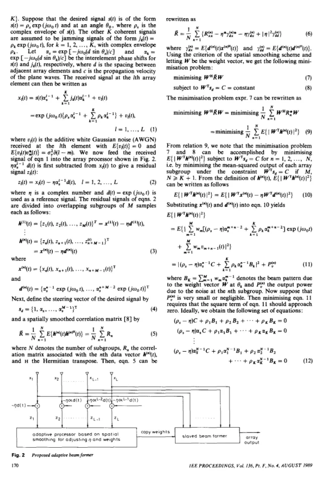
Fig. 1 Array scenarioK}. Suppose that the desired signal s(t) is of the form
s(t) = ps exp (jo,t) and at an angle B o , where ps is the complex envelope of s(t). The other K coherent signals are assumed to be jamming signals of the form j&) =
p k exp (ioo t), for k = 1, 2,
. . .
, K, with complex envelopepk
.
Let a, = exp [ -jw,(d sin BJ/c] and at =exp [ -jwo(d sin Q/c] be the interelement phase shifts for
s(t) and jk(t), respectively, where d is the spacing between adjacent array elements and c is the propagation velocity of the plane waves. The received signal at the Ith array element can then be written as
I
adaptive processor based on spatialsmoothing for adjusting r~ and welghts
where vr(t) is the additive white Gaussian noise (AWGN) received at the Ith element with E{oXt)} = 0 and E{uXt)u$(t)} = u:&i - m). We now feed the received signal of eqn 1 into the array processor shown in Fig. 2. qaf-' d(t) is first subtracted from xdt) to give a residual signal zdt):
(2) where q is a complex number and d(t) = exp
(ioo
t) is used as a reference signal. The residual signals of eqns. 2 are divided into overlapping subgroups of M samples each as follows:zl(t) = xdt) - qaf-'d(t), I = 1 , 2, ..., L
copy weights
array output slaved beam former
h(l)(t) = {zl(t), z2(t),
. . .
, zDl(t)JT = x ( l ) ( t ) - qd(l)(t), h(")(f) = {zn(t), z m + l(tb. . .
> z i ! M - 1)' = X(")(t) - qd'"'(t) (3) where x(")(t) = {xm(t), xn+l(t)? . . . ? x n + M - l ( t ) } ' andd(")(t) = {a;- exp (ioo t),
. . .
, a;+M - 2 exp ( j w , t)}'Next, define the steering vector of the desired signal by
sd = {I, a,,
...,
(4) and a spatially smoothed correlation matrix [8] byrewritten as
where
yg
= E{d(")(t)x(")"(t)} and y$ = E{d'")(t)d("JH(t)}. Using the criterion of the spatial smoothing scheme and letting W be the weight vector, we get the following mini- misation problem:minimising WnR W
subject to W's, = C = constant
The minimisation problem expr. 7 can be rewritten as 1 " N n = 1 minimising WHR W = minimising -
1
W " R ~ W 1 " =minimising -1
E{I
WTh(")(t)1')
N n = 1 (9) From relation 9, we note that the minimisation problem 7 and 8 can be accomplished by minimisingE{
I
WTh(")(t)12} subject to W's, = C for n = 1, 2,.
.., N, i.e. by minimising the mean-squared output of each array subgroup under the constraint W's, = C if M, N 3 K+
1. From the definition of h(")(t), E{I
W'h'")(t)1')
can be written as follows
(IO)
E{
I
W'h'"'(t) 12) = E {I
W'X(")(t) - qW'd'"'(t)J2}Substituting xcn(t) and d(")(t) into eqn. 10 yields E {
I
W'h'"'(t) 12)M K
= E { !
1
w,[(p, - q)ar+"-2+ 1
pka;+"-'] exp(jw,t)m = l k = I M n = l
+
W m u m + n - l ( t ) 1 2 1 K = I(p,-q)a:-'C+ CpkaE-'B,12 + P ? ) (11) k = lwhere B , = w,a;-' denotes the beam pattern due to the weight vector W at Or and P?) the output power due to the noise at the nth subgroup. Now suppose that P f ) is very small or negligible. Then minimising eqn. 11 requires that the square term of eqn. 11 should approach zero. Ideally, we obtain the following set of equations:
@ - q ) C
+
piBi+
~ 2 B 2+
...
+
P K B K= O
( p s - tl)a,C
+
Q l a l B ,+
" '+
P x a K B x = o(p, - q)a;-'C
+
plaY-'Bl+
p 2 a f - ' B 2 where N denotes the number of subgroups, R, the correl-ation matrix associated with the nth data vector h(")(r),
and H the Hermitian transpose. Then, eqn. 5 can be
+
...
+
pKa2-'BK = 0 (12)Fig. 2 Proposed adaptive beamformer
170
I
IEE PROCEEDINGS, Vol. 136, Pt. F , No. 4, A U G U S T 1989
-
If we consider the term ps - q as a variable
B,
then eqns. 12 form a set of linearly homogeneous equations with variables /I, E , ,...,
B,. Furthermore, since (1, a,,...,
and (1, a,,
...,
a:-l}T, k = 1,...,
K, are linearly independent, the solution of eqn. 12 will beB
= B , = B , =...
= B , = 0 provided that M , N>
K+
1. There- fore, the resulting array pattern has nulls in the directions of the jammers,el,
02,. . .
, 0, while satisfying the main beam constraint. Moreover, since = ps - q = 0, i.e.q = p s , the complex envelope of the desired signal can be
estimated. This additional information is useful for deter- mining the existence of the desired signal.
3 Implementation of the new adaptive array
In this Section, we consider the implementation of the proposed array described above. As shown in Fig. 2, the reference signal with unknown envelope qd(t)a:- is sub- tracted from the received signal x,(t) at the Ith sensor to form the difference signal zl(t) of eqn. 2. The difference signals zdt) are then fed into the adaptive beam former to adaptively adjust the variable q and array weights, w l , wz ,
. . .
, w M to achieve the minimisation expressions 7 and 8.Let us proceed with eqn. 10. From the definition of d'"'(t), the term WTd'"'(t) of eqn. 10 is given by
WTd'"'(t) = a:-' exp (jo, t)WTsd (13)
WTd'"'(t) = Ca:-' exp (jo,t) d,(t) (14)
E{
I
WTX'"'(t) - qWTd'"'(t) 12)Substituting the constraint eqn. 8 into eqn. 13, we have
Consequently, eqn. 10 can be rewritten as
= E {
I
WTX'"'(t) - qdn(t)1')
(15) From eqn. 15 we obtainE{
I
WTx(")(t) - qd.(t)1')
= WHRi"!W-qWHyr,-q*WTyd",+ 1q12)C12 (16) Therefore, the minimisation problem becomes :
U
minimising e2 =
2
E(I
WTx"'(t) - qd.(t)12} (17)" = l
subject to WTsd = C (18)
Next, we introduce the Lagrange multiplier I to obtain the equivalent unconstrained minimisation problem as follows:
l N
N n = 1
minimising e: = -
1
E{I
WTx'"'(t) - qd&)12}
- I( WTs, - C)* - I*( WTsd - C ) (19)
Eqn. 19 indicates that the performance measure is a real quadratic function of W and q. Using the gradient method, we take the derivatives of e: with respect to the weight vector
W
and the variable q, respectively, and let C equal one. The results are given as follows(20) V,,,(e:) = 2(1, W -
vu*
-h:)
and
a&aq = -2(
wT'y
- q / N ) whereIEE PROCEEDINGS, Vol. 136, Pt. F , No. 4, A U G U S T 1989
and
Letting eqn. 21 equal zero gives the optimal value of q in terms of the optimal weight vector WO,,
Substituting eqn. 22 into eqn. 20 and letting
ode:)
equal zero, we obtain the optimal weight vectorWO,,
=A(R,
- Ny*fT)-'$ (23)The optimal weight vector is then utilised in a slaved beam former to generate the array output. We note from eqn. 23 that the effect of subtracting qa;-' exp ( j w o t )
from x,(t) as given by eqn. 2 is to eliminate the contnbu- tion of the desired signal component to the spatially smoothed correlation matrix by
fi*fT.
Furthermore, eqn. 23 reveals that the desired signal can be excluded iteratively during the minimisation procedure. Therefore, the resulting array processor tends to suppress all signals involved in the correlation matrixl?,
besides the signal coming from the direction constrained by the steering vector s d . Consequently, the array pattern due to the optimal weight vector will provide a peak in the con- straint direction no matter whether the desired signal exists or not.In the following, we consider the adaptive algorithm for the proposed beam former. Since the associated per- formance measure of the minimisation problem in eqn. 19 is in quadratic form, therefore any gradient-based algorithm can be employed to iteratively adjust the weight settings and the variable q. For instance, the iter- ative equations using the gradient-based method are given as follows:
de2
wdk
+
1) = w,(k) - ii >, i = 1, 2,..
., Mawi
with initial values w,(O) = q(0) = 0, i = 1, 2,
...,
M , where 2 is the step size parameter. The gradients de:/awi and de:/dq are given in eqns. 20 and 21, respectively. Alterna- tively, the direct method may be considered. In this case, what we have to compute at the kth iteration is{l?,
- N y * y T } - ' . A simple recursive equation, such as the
RLS algorithm utilising matrix inversion formulae can be used to estimate the value of {l?,(k) - Nf*(k)fT(k)}-
'.
4 Computer simulations
Several simulation examples are presented in this Section to demonstrate the performance of the proposed adaptive beam-forming algorithm. These simulations were per- formed under the following coherent source environment. The desired signal with complex envelope ps = 6
+
j8 was at an angle 0, = 0". Two coherent jammers withp1 = (10)'l2 and p, = (-0.8
+
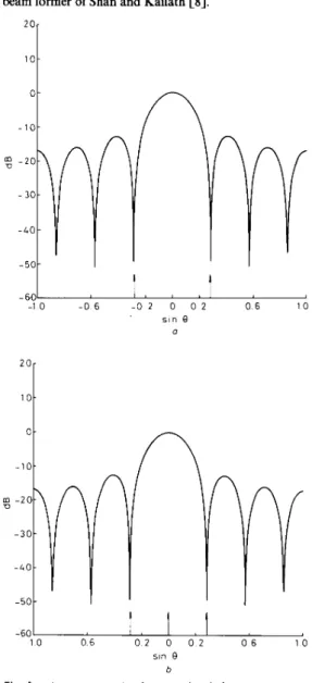
j0.6) (IO)'" arrived at angles O1 and 0, such that sin = -0.29 and sin 0, = 0.29, respectively. The signal-to-each-jammer power ratio was thus 10 dB and the input signal-to-noise ratio (SNR) was set equal to 20 dB. A ten-element linear array was partitioned into four subgroups with a size of seven ele- ments. For all simulations, 800 snapshots were used to estimate the correlation matrices R , of eqn. 5.Fig. 3 shows the resulting array beam patterns using the conventional spatial-smoothing algorithm
[SI.
1 0 -
posed adaptive beam former is greater than that of the beam former of Shan and Kailath
[SI.
1 0 -
I
I 1 I , , , I - 1 0 - 0 6 - 0 2 0 0 2 0 6 1 0 s i n Q a -60 0 6 1 0 -1 0 - 0 6 - 0 2 0 0 2 sin Q a 10 - 6 0 -10 - 0 6 - 0 2 0 0 2 0 6 1 0 s i n e b Fig. 3a Desired signal absent b Desired signal present
Array patterns using spatial smoothing method
Although the array pattern is acceptable when the desired signal is absent, the signal cancellation effect is very severe when the desired signal is present. Moreover, the output SNR is about -122 dB when there is no desired signal, whereas it is about 21 dB when the desired signal is present. In contrast, the array beam patterns using the proposed adaptive beam former are shown in Fig. 4. These two array patterns are almost identical, regardless of the existence of the desired signal. The cor- responding output SNR and qOFt are about - 113 dB and zero, respectively, when the desired signal is absent. They are about 31 dB and 6
+
j 8 , respectively, if the desired signal is present. We see that the output SNR of the pro--60
1 0 0 6 0 2 0 0 2 0 6 1 0
sin Q
b
Fig. 4
a Desired signal absent b Desired signal present
Array patterns using the proposed method
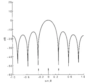
Next, we present an example for a modulated signal to demonstrate the effectiveness of the proposed technique. In this case, the desired signal is p,(r) exp ( j o , t ) with the time-varying complex envelope p&) being given by
(6
+
j 8 ) exp (-0.01~). After about 2 s, the proposed algo-rithm converged to its optimum. Then the resulting optimal weight was employed to operate on the current received signal data to generate the corresponding array beam pattern shown in Fig. 5. The output SNR is about 30 dB and the complex envelope is about 5.9
+
j7.8 for the example. It can be seen that the array pattern is almost the same as that of Fig. 4, where the desired signal is unmodulated. Therefore, the proposed technique iseffective in the case of a modulated signal whose complex envelope is slowly time varying. All the above results confirm the theoretical work presented in Section 2.
direction. Theoretical analysis shows that the complex envelope of the narrowband desired signal can be found exactly as soon as the optimal constrained weight vector solution has been obtained. Moreover, the output signal- to-noise ratio is also useful for determining the existence of the desired signal. Computer simulations support the theoretical work
6 References
2 0
1 MONZINGO, R.A. and MILLER, T.W.: ‘Introduction to adaptive arrays’ (Wiley, New York, 1980)
2 HOWELLS, P.W.: ‘Explorations in fixed and adaptive resolution at G E and SURC‘, IEEE Trans., 1976, AP-24, pp. 575-584
3 APPLEBAUM. S.P.: ‘AdaDtive arravs’. IEEE Trans.. 1976 AP-24.
- 6 0
- 1 0 - 0 6 - 0 2 0 0 2 0 6 1 0 sln,8
Fig. 5 Array pattern for modulated signal using the proposed method
5 Conclusions
In this paper, we have presented one approach to curing the signal cancellation phenomenon inherent in the spatial smoothing algorithm. The resulting adaptive beam former can not only reject coherent jammers effec- tively, but can also preserve the desired signal in the look
967, 55, pp. 2 1 4 3 L13Y
5 APPLEBAUM, S.P., and CHAPMAN, D.J.: ‘Adaptive arrays with main beam constraints’, IEEE Trans., 1976, AP-24, pp. 6 5 M 6 2 6 FROST, O.L.: ‘An algorithm for linear constrained adaptive array
processing’, Proc. IEEE, 1972.60, pp. 926935
7 GRIFFITHS, L.J., and JIM, C.W.: ‘An alternative approach to lin- early constrained adaptive beamforming’, IEEE Trans., 1982, AP-30, pp. 27-34
8 SHAN T.-J., and KAILATH, T.: ‘Adaptive beamforming for coher- ent signal and interference’, IEEE Trans., 1985, ASSP-33, pp. 527-536
9 EVANS, J.E., JOHNSON, J.R., and SUN, D.F.: ‘Application of advanced signal processing techniques to angle of arrival estimation in ATC navigation and surveillance systems’. Lincoln Lab. Tech. Rep. 582, June 1982
10 WIDROW, B., DUVALL, K.M., GOOCH, R.P., and NEWMAN, W.C.: ‘Signal cancellation phenomena in adaptive antennas: causes and cures’, IEEE Trans., 1982, AP-30, pp. 469-478
11 REDDY, V.U., PAULRAJ, A., and KAILATH, T.: ‘Performance analysis of the optimal beamformer in the presence of correlated sources and its behaviour under spatial smoothing’, IEEE Trans., 1987, ASSP-35, pp. 927-936
12 PEI, S.-C., YEH, C.-C., and CHIU, S.-C.: ‘Modified spatial smooth- ing for coherent jammer suppression without signal cancellation’, to be published in IEEE Trans., ASSP
IEE PROCEEDINGS, Vol. 136, Pt. F , No. 4, AUGUST 1989
1
T-
173