Automatic Co-Registration of Optical Satellite
Images and Airborne Lidar Data Using Relative and
Absolute Orientations
Tee-Ann Teo and Shih-Han Huang
Abstract—Co-registration of 2-D images and 3-D lidar points in a common area is an important task in data fusion as well as other applications. As the information acquired by image and lidar sys-tems are not the same, the registration of heterogeneous sensors is a challenging issue. The objective of this study is to perform the co-registration of 2-D images and 3-D lidar points using relative and absolute orientations. The proposed method performs image matching between stereo images for relative orientation modeling and generates a matched 3-D surface model. Then, an automatic least squares 3-D surface matching is applied between matched 3-D surface model and lidar 3-D points. Finally, the precise object-to-image transformation and orthoobject-to-images can be generated via rel-ative and absolute transformation. The test data include World-View-2 image, QuickBird image and lidar data. The experimental results indicate that the relative orientation may reach subpixel ac-curacy while the absolute orientation may reach 1 pixel acac-curacy. Moreover, the geometric consistency between orthoimages is better than 0.5 m on the ground.
Index Terms—High resolution satellite images, least squares 3-D surface matching, lidar point clouds, registration.
I. INTRODUCTION
A
CTIVE and passive sensors are two commonly used sen-sors. Active sensors provide their own energy source for illumination; for example, the lidar system uses a laser scanner to acquire three-dimensional (3-D) point clouds of land surface. In comparison, passive sensors are used to detect energy that is naturally available; for example, optical sensors acquire two-di-mensional (2-D) images of land surface. Therefore, the informa-tion acquired by passive optical and active lidar sensors is not the same. In many applications, different sensors must be de-ployed in the same area for interpretation and analysis to gain more useful knowledge for the application. Hence, co-registra-tion is an important preprocessing [1] step in data fusion.The development of high resolution satellites not only fo-cuses on improving spatial and spectral resolution, but also time resolution. As most high resolution satellites are capable of body rotation to acquire in-track multi-look images, their agility en-hances the capability to acquire multiple images over a given location in a single path. Moreover, the satellite constellation
Manuscript received August 10, 2012; revised November 16, 2012; accepted December 17, 2012. Date of publication January 18, 2013; date of current ver-sion September 20, 2013. This work was supported in part by National Science Council of Taiwan. (Corresponding author: T.-A. Teo.)
The authors are with the Department of Civil Engineering, National Chiao Tung University, Taiwan (e-mail: tateo@mail.nctu.edu.tw).
Color versions of one or more of the figures in this paper are available online at http://ieeexplore.ieee.org.
Digital Object Identifier 10.1109/JSTARS.2012.2237543
also offers acquisition and revisiting capacity using a number of satellites. The improved time resolution of recent satellites such as QuickBird and WorldView series can be used in object reconstruction [2], change detection [3], object tracking [4], and other applications.
Lidar is a well-established technique for deriving 3-D infor-mation for mapping and GIS tasks. The lidar system integrates a laser scanner, a Global Position System (GPS) and an Inertial Navigation System (INS), and thus is an effective technology to obtain 3-D surface models. In addition, it has a high preci-sion laser ranging and scanning orientation made for decimeter ground surface accuracy. The accuracy of lidar data is generally sufficient to be used as reference data for geometric correction of satellite images.
In order to compensate for orientation errors of satellite im-ages, lidar data can be applied to improve the positioning ac-curacy of satellite images. Moreover, the digital surface model (DSM) from lidar can be used to correct the relief displacements in ortho-rectification of satellite images. Hence, the benefits of integrated satellite images and lidar are the accuracy and au-tomation improvement in geo-processing.
The co-registration of satellite images includes radiometric and geometric process. The radiometrical co-registration is used to obtain uniform radiometric response between images [5]. Ge-ometrical co-registration is necessary to correct for relief dis-placement of terrain and distortion arising from the viewing ge-ometry. Geometrical co-registration of lidar and images aims to provide accurate transformation between 2-D image space and 3-D lidar object space, but the process can be challenging for several reasons. The lidar system acquires shape information, while an image sensor acquires spectral information. Moreover, the acquired lidar data is in the form of 3-D points using ob-ject coordinates, while the acquired image is in the form of 2-D grid using image coordinates. Both lidar and image capture the information of land surface, but display with different represen-tations. The lidar data uses an orthographic projection while the image data uses a perspective projection.
The direct approach to achieving co-registration of the lidar data and the imagery data would be to identify well-defined feature points which can be located in both the lidar 3-D ject model, and in the 2-D imagery. The coordinates of an ob-ject point in both lidar and image data are called registration point. Registration points are used to calculate the transforma-tion coefficients in co-registratransforma-tion. However, it is not easy to measure well-defined feature points from irregular lidar point clouds. In order to overcome the problem of registration points, Habib et al. [6] proposed to use linear features as registration
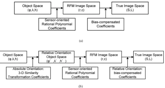
Fig. 1. Comparison of the traditional and proposed image transformation. (a) Traditional image space transformation (b) Proposed object-to-image space transformation.
entities for the registration of lidar and aerial images. Several re-searchers have reported on the registration of lidar and a single image. Abedini et al. [7] and Toth et al. [8] used the scale-in-variant feature transform (SIFT) approach for the registration of lidar intensity data and optical imagery. Palenichka et al. [9] used salient image disks (SID) to extract the control points for the registration of lidar range data and a QuickBird image. Kwak et al. [10] performed the registration of aerial imagery and lidar data using centroids of plane roof surfaces. Lee et al. [11] minimized the summation of absolute difference between the edges from lidar and satellite images. Most of the studies fo-cused on direct matching between lidar and single image via fea-ture-based matching; relatively few studies discussed the regis-tration of lidar and satellite stereo images.
The traditional stereoscopic mapping procedures for aerial stereo images include relative and absolute orientations [12]. Relative orientation performs image matching between stereo images, and the extracted tie point is then used to establish the relative model between stereo images [13]. It is used to deter-mine the relative rotation angles and positional displacements between two overlapped images, as well as to obtain a relative stereo model without true world coordinates. Absolute orienta-tion uses 3-D similarity transformaorienta-tion to transform the relative model into an absolute model representing a true 3-D model [14]. It uses ground control points to align the relative stereo model into real world coordinate system.
In this study, we propose an automatic approach for the reg-istration of lidar and satellite stereo images, inspired by tradi-tional aerial image processing. The objective is to develop an automatic co-registration procedure for lidar and satellite stereo images using relative and absolute orientations. In order to over-come the problem of different information captured from dif-ferent sensors, the proposed method performs image matching between stereo images for relative orientation modeling and generates the matched 3-D surface model. Then, an automatic least squares 3-D surface matching [15] is applied between the stereo image of 3-D surface model and lidar 3-D points. Finally,
the precise object-to-image transformation and orthoimages can be generated via relative and absolute transformations.
The satellite sensor model in this study is the rational function model (RFM). The coefficients of RFM are called sensor-ori-ented rational polynomial coefficients (RPCs), which are pro-vided by a satellite vendor and recorded in the metadata of satel-lite images. Due to the standardization and simplicity, RFM has been widely used for high resolution satellite image [16]. A comparison of the traditional and proposed object-to-image space transformation (Fig. 1) shows that the traditional approach extracts the registration points between lidar and image directly and calculates the bias-compensated coefficients from registra-tion points. In Fig. 1(a), “object space” is the ground coordinates of a point while the “true image space” indicates the real image coordinate without RFM’s model errors. The 3-D ground co-ordinates can be transformed to RFM image coco-ordinates using sensor-oriented RPCs in the metadata. As the sensor-oriented RPCs contain errors, we need additional bias-compensated co-efficients to transform a point in RFM image space to true image space. In this approach, the sensor-oriented RPCs are recorded in the metadata while the bias-compensated coefficients are cal-culated from registration points between lidar and image.
Fig. 1(b) shows the idea of the proposed method. The pro-posed method is a two-step transformation (i.e., relative and ab-solute orientations) in which an object point in object space is transformed to the relative model; the point in the relative model is then further transformed to image space. In this approach, the coefficients of absolute orientation are calculated from the lidar surface and stereo image surface. The bias-compensated coef-ficients are calculated from registration points between satellite images. The proposed method comprises three major steps: (1) relative orientation between satellite stereo images; (2) DSM generation from satellite stereo images; and (3) absolute orien-tation using lidar points and image matched DSM.
Today the geolocation accuracy of high resolution satellites refers to the accuracy of the on-board global positioning system (GPS) and inertial navigation system (INS) to support direct
platform orientation. For example, QuickBird and WorldView-2 are capable of 23 m [17] and 3.5 m [18] geolocation accuracy without using ground control points (GCPs). For medium res-olution satellites such as SPOT-1 to SPOT-4, the geolocation accuracies without GCPs are about 350 m [19]. The geoloca-tion accuracy of high resolugeoloca-tion satellite is relatively better than medium resolution satellite image. Several studies indicate that the sensor-oriented rational polynomials coefficients of satellite images have high relative accuracy [20] and, consequently, the image matched 3-D surface model closely resembles the object surface model. Moreover, the initial alignment between stereo images for relative orientation is sufficient that a manual initial tie point is not needed in these types of high resolution satellite images [21]. The initial disorientation between QuickBird and WorldView-2 images refers to the geolocation accuracy. The au-tomatic coarse-to-fine image matching based on image pyramid is able to handle the disorientation [21].
The main motivation of this research is to verify the possi-bility of the co-registration of RFM-based satellite stereo im-ages and lidar point clouds using relative and absolute orien-tations. The major contribution of this research is to propose an automatic procedure for the registration of lidar and satellite stereo images via relative and absolute orientations. The pro-posed method does not perform matching between image and lidar directly. It generates the matched 3-D surface from satel-lite stereo images and then applies a 3-D surface matcher to the image matched 3-D surface and lidar 3-D points for absolute orientation. This process is used to avoid the problem of dif-ferent information between images and lidar.
The scope of this research is the automatism of data co-regis-tration between stereo images and lidar point clouds. This study assumes that the stereo images contain sufficient image features for image matching and 3-D surface generation. Moreover, the 3-D surface model contains sufficient variation in height di-rection. The surface matching needs different elevations to de-termine the absolute orientation. In other words, the proposed method is not suitable for flat terrain with very little variation in elevation.
II. THEPROPOSEDSCHEME
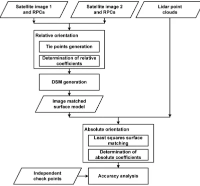
The proposed method comprises three major steps: (1) rela-tive orientation; (2) DSM generation; and (3) absolute orienta-tion. The workflow of proposed method is shown as Fig. 2 and the details of each step are given below.
A. Relative Orientation
Relative orientation improves the relative consistency be-tween stereo images and also generates geometric constrained stereo model for absolute orientation. Relative orientation includes two major parts. First, area-based image matching is used to generate tie points between stereo images; second, relative orientation is carried out using the rational function model and bias compensation function [20], [22].
An area-based image matching, which calculates the simi-larity of gray values, is selected for tie-point generation using satellite stereo images. The initial matching uses normalized cross correlation (NCC) [23] while the precise matching uses least squares image matching [24]. In order to reduce the
pull-in-Fig. 2. Work flow of proposed method.
range at the stage of image matching, we employ an image pyramid to refine the matching results iteratively.
The RFM uses the ratio of two cubic polynomials to describe the relationship between object space and image space [25]; the RFM bias compensation model is selected for this study [26]. The bias compensation can be performed in either object space [22] or image space [26]. The object space model compensates the biases in absolute positioning via ground control points. In this study, we only have tie points as the ground control points are not available. Hence, the image space model is selected in relative orientation. Relative orientation of RFM determines the bias compensation coefficients using tie points. Equation (1) is the mathematic model of RFM. The coefficients of RFM are available in the metadata. In this study, RFM is used to describe the relationship between object coordinates and RFM’s image coordinates. Equation (2) is the bias compensation equation for relative orientation. The bias compensation equation is to min-imize the using bias compensation coefficients. The observations are the image coordinates of matched tie points while the unknown parameters are the bias compensation coef-ficients and object coordinates of tie point [22]. For a stereo pair, a tie point can establish four observation equations. When the number of tie points is greater than 12, a least squares adjustment technique is applied to solve the un-known parameters.
(1)
(2) (3)
where
are the image coordinates in RFM image space; are the object coordinates;
are polynomial functions in third-order polynomials;
are the image coordinates in true image space; are the biases in image space;
are the bias compensation coefficients; is number of point; and
is number of image. B. DSM Generation
The image matching in relative orientation is used to deter-mine a small number of well distributed tie points. The role of extracted tie points is to determinate the bias compensation coefficients in relative orientation. After relative orientation, the relationship between stereo images is established. We use a hierarchical template matching strategy for automatic DSM generation using satellite stereo images. It is used to determine dense tie points for space intersection. A coarse global DSM and image pyramid are applied to reduce the pull-in-range in image matching [27]. Image matching and DSM generation are proceeded with a coarse-to-fine strategy. Least squares image matching also applied to refine the matching accuracy [24]. Blunder error detection uses geometrical constrain to remove outliers with large disparity points. An interpolation after image matching is also applied in DSM generation. The final product of DSM generation is a large number of irregular 3-D points and interpolated DSM. Notice that, the coordinates of the generated DSM are not the true object coordinates. C. Absolute Orientation
The relative orientation of satellite images only applies tie points. No additional ground control points are involved in rel-ative orientation. Therefore, the coordinates of image-matched DSM are still a relative model. As the very high resolution satel-lite images usually have good geolocation accuracy, the coordi-nates of the image-matched DSM are similar to the real world coordinate. On the contrary, the lidar-derived DSM in this study represents a DSM in a real world coordinates. So, we use the lidar DSM to provide ground control information and transform the image-matched DSM from relative coordinates to the real world coordinates.
Absolute orientation is used to build up a transformation be-tween image-matched DSM and lidar-derived DSM. Three-di-mensional similarity transformation function is widely used in absolute orientation. As both data represent the shape of the sur-face, a least squares 3-D surface matching is applied to deter-mine the transformation parameters from relative model to ab-solute model.
The traditional absolute orientation measures the 3-D regis-tration points between image-matched and lidar surfaces; the
transformation coefficients are then calculated from 3-D reg-istration points. As the aim of this research is to improve the automation of the data co-registration, we use a least squares 3-D surface matching approach to find the conjugate surfaces between image-matched and lidar surfaces.
Least squares 3-D surface matching was developed by Gruen and Akca [15]. This method assumes that two surfaces are created from the same object by different processes. In this study, one surface acquired by lidar is called the template surface , while the other surface from image matching is called the search surface . If the error function is zero, these two surfaces should be the same, and all the patch surface in the template surface can correspond to the patch surface in the search surface as shown in (4).
In reality, the two surfaces are not totally equal. We use error function to describe the inconsistency between the two conjugate surfaces. Hence, (4) can be rewritten as (5). In order to minimize the error function , the coordinate system of the image-matched DSM are being sub-jected to a general 3-D translation, scaling and rotation trans-formation (the so called “similarity transtrans-formation”). It is used to minimize the integrated squared error function between these two conjugate surfaces over a well define common spatial do-main. The transformation parameters of similarity transforma-tion include a translatransforma-tion vector , three rotation an-gles and one scale factor. These parameters are used to minimize the errors between these two conjugate surfaces.
(4) (5)
(6) where
and are the template and search surfaces; is error vector;
are the coordinate system of lidar-derived surface;
are the coordinate system of image-matched surface;
, and are the three translation parameters along three axes;
are elements of the rotation matrix formed by three rotation angles , and around three axes; and
is the scale factor we assume is close to 1. The image matched 3-D points and lidar 3-D points are struc-turalized by a voxel structure. The points located in a voxel are used to calculate the normal vectors and plane equations for surface matching. We iteratively minimize the sum of squared errors between image-matched and lidar surface using least squares 3-D matching approach. A more in depth description of
TABLE I
INFORMATIONRELATED TOTESTIMAGES
Fig. 3. Test data and matched result. (a) QuickBird Image. (b) WorldView-2 Image. (c) Lidar 3-D Points. (d) Matched 3-D Points.
the least squares adjustment details, in regards to the parameters determination can be found in Akca (2007) [28].
III. EXPERIMENTALRESULT
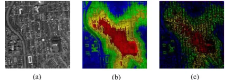
The test data include very high resolution satellite images and lidar data from the IEEE 2012 Data Fusion Contest [29]. The test area is located in downtown San Francisco, California.
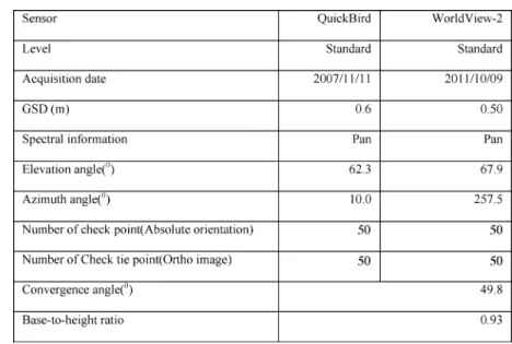
The satellite images are WorldView-2 and QuickBird panchro-matic satellite images provided by DigitalGlobe. The test im-ages (Fig. 3(a) and (b)) show that the base-to-height ratio for this stereo pair is about 0.93. The related parameters for the rest of the images were summarized (Table I). The lidar data acquired by Optech ALTM 3100 in June 2010 (provided by USGS) show that the area of lidar data is about 30 km and the average point density is about 2 pts/m . The elevation of the test site has about 70 m relief (Fig. 3(c)).
The validation experiments are carried out in three parts. First, the geometrical consistency after relative orientation is evaluated; second, the absolute accuracy is examined and third, orthoimages generated from the proposed methods are checked. The independent check points for absolute accuracy and check tie points for orthoimage assessment are acquired by manual measurements.
A. Accuracy of Relative Orientation
The first step of relative orientation is to extract tie points by image matching. The image pyramid has five layers. The target and search windows for NCC are 7 pixels and 21 pixels, respec-tively. The correlation threshold of NCC is 0.8. After NCC ini-tial matching, least squares image matching is applied to refine the matching results. The window size for least squares image matching is 21 pixels.
As these two images are 100% overlapped, 39 well-dis-tributed tie points are extracted and checked manually. Since these two images are georeferenced by satellite’s on-board data, the initial geolocation of these two images is more accurate than 23 m without terrain effect [17], [18]. The result indicates that all of the automatic tie points are correct.
These tie points are used to calculate the bias compensation coefficients – in (3). Equation (7) is used to evaluate the curacy and suitability of this bias compensation model. The ac-curacy of relative orientation using an automatic matching and RFM bias compensation model (Table II) show that the
root-Fig. 4. Error vector of relative orientation modeling. (a) Error vector of Quick-Bird (b) Error vector of Worldview-2.
TABLE II
ACCURACY OFRELATIVEORIENTATION(UNIT: PIXEL)
mean-square errors (RMSEs) for both images achieved subpixel accuracy. These results (Table II) indicate that the bias compen-sation model is suitable for relative orientation. Moreover, the matching tie points for relative orientation may reach subpixel accuracy. Fig. 4 shows the error vector of relative orientation modeling.
(7) where
are the residuals of relative orientation in image space
are the image coordinates in RFM image space; are the image coordinates of tie points in true image space; and
are the bias compensation coefficients.
B. Accuracy of Absolute Orientation
After relative orientation, this study uses a commercial soft-ware ERDAS eATE [30] to generate surface models. The area for image matching is the same as lidar data, and the test area is about 10 km 5 km. The total number of matched 3-D points is 3 801 376 and the average point density is 0.2 pts/m . As these two satellite images were taken in 2007 and 2011, some changed areas may affect the matching results. The matching rate in this study is about 62%, indicating that the feature is significant and correlation is high. The matching rate means the successful rate in image matching. The study area covers homogeneous ocean
Fig. 5. Comparison of lidar and matched 3-D points. (a) Reference image. (b) Lidar points. (c) Matched points.
area. The homogeneous area usually does not have significant features for matching. As the ocean area is about 40% of study area, 62% matching rate is relatively high in this study case. We subset a small area of matched and lidar points for com-parison (Fig. 5). We only have two images for image matching and, consequently, the point density is lower than lidar, espe-cially in the homogeneous area. In addition to the point density, these two surface models look similar and can be used for sur-face matching.
We employ least squares 3-D surface matching, an auto-matic surface registration process that iteratively minimizes the difference between image-matched and lidar surfaces, to determine the coefficients of 3-D similarity transformation. The stopping criterion of the iterative process depends on whether the unknown parameters are the same during the iteration. Although the point density of lidar and matched points of building and road profiles before and after surface matching are not the same (Fig. 6), surface matching is able to transform the matched points into lidar object space.
We carefully select 50 independent check points collected from lidar surface, lidar intensity, and satellite images to eval-uate the object-to-image transformation. To avoid the problem of height discontinuous in check point selection, we mainly se-lect the well-defined check points on the ground surface. These check points are mainly located at the area of road marks. The elevation of check points is ranged from 0 m to 70 m. The ob-ject-to-image transformation (Fig. 1(b)) integrates the coeffi-cients of 3-D similarity transform, sensor-oriented rational poly-nomial coefficients provided by satellite vendor, and bias-com-pensation coefficients in relative orientation.
The accuracy of object-to-image transformation using the proposed method (Table III) shows that before absolute orientation the RMSEs of check points for QuickBird and WorldView-2 in sample and line direction are ranged from 1 to 9 pixels; after absolute orientation, the RMSE of check point improved to 1 pixel. The RMSE for both images achieved 1 pixel accuracy in the sample and line direction, respec-tively. The experimental results indicate that the 3-D similarity transformation is suitable for the transformation from relative model to absolute model. Moreover, least squares 3-D surface matching is able to build up the relationship between the two surfaces. Fig. 7 shows the error vector of absolute orientation modeling. The directions of error vectors indicate that no systematic error in the absolute orientation.
In the computation time analysis, we use a personal computer with a 3.60 GHz CPU and 16 GB Memory for relative tion, DSM generation and absolute orientation. Relative
orienta-Fig. 6. Comparison of lidar and matched 3-D points before and after surface matching. (a) Building profile before surface matching (Blue: lidar; Green: orig-inal point). (b) building profile after surface matching (Blue: lidar; Red: trans-formed point). (c) road profile before surface matching (Blue: lidar; Green: orig-inal point). (d) road profile after surface matching (Blue: lidar; Red: transformed point).
tion includes image matching for tie points and parameter deter-mination for bias compensate model. The total time is about 10 minutes and most of the computation time is spent on pyramid image matching. DSM generation is time consuming, as it is a dense-points extraction process. It takes 180 minutes to ex-tract 3.8 million points on a 10 km 5 km area. Absolute orien-tation includes structuralization of irregular points, calculation of plane equation from voxel and least squares 3-D matching for similarity transformation. The computation time for abso-lute orientation is about 60 minutes and most of the computa-tion time is spent on plane equacomputa-tion calculacomputa-tion. In this study, we have spent 250 minutes computation time to obtain high ac-curate transformation parameters between satellite images and lidar data automatically.
C. Effect of Point Density
In image matching, the difference between spatial resolution images, called scale factor, is important. This problem also oc-curs in 3-D surface matching, in which the difference of point density between two surfaces is also an important factor.
In order to evaluate the impact of point density, we reduce the lidar and matched points into different point densities. The image matching usually matches the top of the object; hence, the point reduction only samples the highest point in different
Fig. 7. Error vectors of absolute orientation modeling. (a) Error vectors of QuickBird. (b) Error vectors of Worldview-2.
TABLE III
ACCURACY OFABSOLUTEORIENTATION(UNIT: PIXEL)
grid sizes. The highest density of the image matched surface is 0.2 pts/m ; therefore, the point densities in this analysis are 0.2, 0.1, 0.05, and 0.025 pts/m . We use 50 manually selected independent check points to evaluate the object-to-image trans-formation. A summary of different point densities (Table IV) in-dicates that the accuracy of check points improved as the point density increased and that the point density is a significant factor in 3-D surface matching.
D. Geometric Consistency of Orthoimages
The objective of this research is to generate accurate trans-formation coefficients between images and lidar. Besides, we can also use the transformation coefficients in orthorectification. In order to check the geometric consistency between 2-D im-ages and 3-D lidar data, we use lidar DSM in satellite image orthorectification. The coefficients of object-to-image transfor-mation are the results of relative and absolute orientations. If
TABLE IV
ACCURACY OFABSOLUTEORIENTATION INDIFFERENTPOINTDENSITIES(UNIT: PIXEL)
the images and lidar are well co-registrated, then, the tie point appears at the same position in orthoimages.
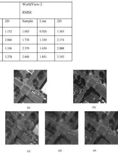
We generate three types of orthoimages. The first uses only the sensor-oriented rational polynomial coefficients (RPCs) to generate orthoimages; the second integrates RPCs and coeffi-cients of relative orientation; the third combines RPCs and co-efficients of relative and absolute orientations. Orthoretification is used to remove the terrain distortion and convert the perspec-tive projection into orthographic projection. The orthorectifi-cation yields map-accurate image with real world coordinates. The research generates QuickBird and WorldView-2 orthoim-ages from orientation parameters (relative and absolute orien-tations) and lidar surface models. Then, we overlap these two orthoimages to check the geometric consistence. The discrep-ancy in orthoimages is small when the transformation between image and lidar is accurate. These three types of orthoimages (Fig. 8) indicate that orthoimages that use only RPCs may cause significant displacement (Fig. 8(c)). This phenomenon is espe-cially obvious when the terrain is steep. Relative orientation im-proves the relative accuracy between images (Fig. 8(d)); how-ever, there is no connection between relative orientation and lidar surface. High consistency is evident between the two or-thoimages as the absolute orientation establishes the relation-ship between image-matched and lidar surfaces (Fig. 8(e)).
We manually select 50 check tie points in orthoimages to evaluate the geometric consistency and choose a pair of tie points that appeared in the two orthoimages. The distance between these two ground positions is used to evaluate the discrepancy (Table V). The result of RPC is about 25 m, but after relative orientation, the discrepancy is reduced to 5 m. Finally, the discrepancy is reduced to 0.5 m (about 1 pixel) when absolute orientation is applied. The experimental results indicate that the proposed method can achieve high accuracy.
IV. CONCLUSION
In this study, we proposed an automatic co-registration procedure for very high resolution satellite stereo images and lidar point clouds. The proposed method consists of three major steps: (1) image matching for relative orientation, (2) image matching for DSM generation, and (3) 3-D surface matching for absolute orientation. The proposed method does not per-form the matching between image and lidar data directly. The
Fig. 8. Comparison of different types of orthoimages. (a) WorldView-2 image. (b) QuickBird image. (c) Overlapped orthoimages (RPCs only). (d) Overlapped orthoimages (RPCs and relative orientation). (e) Overlapped orthoimages (RPCs, relative and absolute orientations).
TABLE V
COMPARISON OFGEOMETRICALCONSISTENCYBETWEENQUICKBIRD AND WORLDVIEW-2 IMAGES(UNIT: METER)
advantage is to avoid the problem of different acquired infor-mation between images and lidar; the limitation of this research is that the images in use should be multi-images. Moreover, flat terrain with very little elevation variation is not suitable for absolute orientation. In this study, the test images have high geolocation accuracy, therefore, there is no need for initial manual-measured tie points. In case the geolocation accuracy of images is not good enough, manual intervention is needed.
The experimental results indicate that relative orientation may reach subpixel accuracy while absolute orientation may reach 1 pixel accuracy. Moreover, the geometric consistency
between orthoimages may reach 0.5 m on the ground. Test re-sults indicate that the proposed method is feasible and rigorous. This study also analyzes the impact of point density in 3-D surface matching. The quality of image-matched 3-D points may affect the registration accuracy.
This model can be applied to other satellite images and sur-face data. This study uses optical images to generate matched DSM for surface matching. As the radar images can also gen-erate DSM, future work will focus on the co-registration of stereo radar images and range data.
ACKNOWLEDGMENT
The authors would like to thank DigitalGlobe and USGS for providing the imagery used in this study, and the IEEE GRSS Data Fusion Technical Committee for organizing the 2012 Data Fusion Contest.
REFERENCES
[1] B. Zitová and J. Flusser, “Image registration methods: A survey,”
Image and Vision Computing, vol. 21, no. 977–1000, 2003.
[2] G. A. Licciardi et al., “Retrieval of the height of buildings from World-View-2 multi-angular imagery using attribute filters and geometric in-variant moments,” IEEE J. Sel. Topics Appl. Earth Observ. Remote
Sens., vol. 5, no. 1, pp. 71–79, 2012.
[3] F. Bovolo, “A multilevel parcel-based approach to change detection in very high resolution multitemporal image,” IEEE Geosci. Remote
Sens. Lett., vol. 6, no. 1, pp. 33–37, 2009.
[4] B. Salehi, Y. Zhang, and M. Zhong, “Automatic moving vehicles in-formation extraction from single-pass WorldView-2 imagery,” IEEE
J. Sel. Topics Appl. Earth Observ. Remote Sens., vol. 5, no. 1, pp.
135–145, 2012.
[5] Y. Li and C. H. Davis, “Pixel-based invariant feature extraction and its application to radiometric co-registration for multi-temporal high-resolution satellite imagery,” IEEE J. Sel. Topics Appl. Earth Observ.
Remote Sens., vol. 4, no. 2, pp. 348–360, 2011.
[6] A. F. Habib et al., “Photogrammetric and LIDAR data registration using linear features,” Photogramm. Eng. Remote Sens., vol. 71, no. 6, pp. 699–707, 2005.
[7] A. Abedini, M. Hahn, and F. Samadzadegan, “An investigation into the registration of LIDAR intensity data and aerial images using the SIFT approach,” Int. Archives Photogrammetry, Remote Sensing and Spatial
Information Sciences, vol. 37, no. B1, pp. 169–174, 2008.
[8] C. Toth, H. Ju, and D. Grejner-Brezezinsk, “Matching between dif-ferent image domains,” Lecture Notes on Computer Science, vol. 6952, pp. 37–47, 2011.
[9] R. M. Palenichka and M. B. Zaremba, “Automatic extraction of control points for the registration of optical satellite and lidar images,” IEEE
Trans. Geosci. Remote Sens., vol. 48, no. 7, pp. 2864–2879, 2010.
[10] T.-S. Kwak et al., “Registration of aerial imagery and aerial LiDAR data using centroids of plane roof surfaces as control information,”
KSCE J. Civil Eng., vol. 10, no. 5, pp. 365–370, 2006.
[11] J. Lee, C. Lee, and K. Yu, “Autoregistration of high-resolution satellite imagery using lidar intensity data,” KSCE J. Civil Eng., vol. 15, no. 2, pp. 375–384, 2011.
[12] P. R. Wolf and B. A. Dewitt, Elements of Photogrammetry with
Appli-cations in GIS, 3rd ed. New York: McGraw-Hill, 2000.
[13] T. Liang and C. Heipke, “Automatic relative orientation of aerial im-ages,” Photogramm. Eng. Remote Sens., vol. 62, no. 1, pp. 47–55, 1996. [14] D. Rosenholm and K. Torlegard, “Three-dimensional absolute orien-tation of stereo models using digital elevation model,” Photogramm.
Eng. Remote Sens., vol. 54, no. 10, pp. 1385–1389, 1988.
[15] A. Gruen and D. Akca, “Least squares 3D surface and curve matching,”
ISPRS J. Photogramm. Remote Sens., vol. 59, no. 3, pp. 151–174, 2005.
[16] OGC, “The OpenGIS abstract specification—Topic 7: The earth im-agery case, version 4,” OpenGIS Consortium pp. 14–16, 1999. [17] DigitalGlobe, QuickBird Spacecraft Datasheet. 2012 [Online].
Avail-able: http://www.digitalglobe.com/downloads/QuickBird-DS-QB-Web.pdf
[18] DigitalGlobe, WorldView-2 Spacecraft Datasheet. 2012 [On-line]. Available: http://www.digitalglobe.com/downloads/World-View2-DS-WV2-Web.pdf
[19] CNES, “Accuracy and coverage combined of SPOT image,” SPOT Image. 2005 [Online]. Available: http://www.isis-cnes.fr/pages/sta-tique/spotProduct_en.pdf
[20] C. S. Fraser and H. B. Hanley, “Bias-compensated RPCs for sensor ori-entation of high-resolution satellite imagery,” Photogramm. Eng.
Re-mote Sens., vol. 71, no. 8, pp. 909–915, 2005.
[21] S. R. Lee, “A coarse-to-fine approach for remote-sensing image regis-tration based on a local method,” Int. J. Smart Sens. Intell. Syst., vol. 3, no. 4, pp. 690–702, 2010.
[22] H.-G. Sohn, C.-H. Park, and H. Chang, “Rational function model-based image matching for digital elevation models,” Photogramm. Rec., vol. 20, no. 112, pp. 366–383, 2005.
[23] T. Schenk, Digital Photogrammetry. Laurelville, OH: TerraScience, 1999.
[24] A. Gruen, “Adaptive least squares correlation: A powerful image matching technique,” South African J. Photogramm., Remote Sens.
Cartogr., vol. 14, no. 3, pp. 175–187, 1985.
[25] C. V. Tao and Y. Hu, “A comprehensive study of the rational function model for photogrammetric processing,” Photogramm. Eng. Remote
Sens., vol. 67, no. 12, pp. 1347–1357, 2001.
[26] C. S. Fraser and H. B. Hanley, “Bias compensation in rational function for IKONOS satellite imagery,” Photogramm. Eng. Remote Sens., vol. 69, no. 1, pp. 53–57, 2003.
[27] L. C. Chen and J. Y. Rau, “A unified solution for digital terrain model and orthoimage generations from SPOT stereopairs,” IEEE Trans.
Geosci. Remote Sens., vol. 31, no. 6, pp. 1243–1252, 1993.
[28] D. Akca, Least Squares 3D Surface Matching. ETH Zurich, Switzer-land: Inst. Geodesy and Photogrammetry, 2007.
[29] IEEE, “2012 IEEE GRSS data fusion contest,” [Online]. Available: http://www.grss-ieee.org/community/technical-committees/data-fu-sion/data-fusion-contest/
[30] “User’s guide of enhanced automatic terrain extraction (eATE),” Erdas Imagine p. 48, 2010.
Tee-Ann Teo received the M.S.E. and Ph.D. degrees
from the Department of Civil Engineering, National Central University, Taiwan, in 2002 and 2008, respectively.
He was with the Center for Space and Remote Sensing Research, National Central University, as a Postdoctoral Research Fellow in 2008. He is cur-rently an Assistant Professor with the Department of Civil Engineering, National Chiao Tung University, Hsinchu, Taiwan. His research activities are focused on cyber city modeling, geometrical data processing for remotely sensed data, and lidar processing.
Shih-Han Huang received the B.S. degree from the
Department of Geomatics, National Cheng Kung University, Taiwan, in 2010, and the M.S.E. degree from the Department of Civil Engineering from National Chiao Tung University, Taiwan, in 2012.
His research activities are focused on lidar pro-cessing.