A direct approach to the modeling of polydihexylsilane as a contrast enhancement
material
Wenan Loong and Hongtsz Pan
Citation: Journal of Vacuum Science & Technology B 8, 1731 (1990); doi: 10.1116/1.585148 View online: http://dx.doi.org/10.1116/1.585148
View Table of Contents: http://scitation.aip.org/content/avs/journal/jvstb/8/6?ver=pdfcov Published by the AVS: Science & Technology of Materials, Interfaces, and Processing
Articles you may be interested in
Modeling of high contrast partially electroded resonators by means of a polynomial approach J. Appl. Phys. 114, 124502 (2013); 10.1063/1.4821768
The role of graphene in enhancing the stiffness of polymeric material: A molecular modeling approach J. Appl. Phys. 113, 243503 (2013); 10.1063/1.4812275
Applications of contrast enhancement material to photobleachable deep ultraviolet resist J. Vac. Sci. Technol. B 7, 1072 (1989); 10.1116/1.584596
Excimer laser lithography using contrast enhancing material J. Vac. Sci. Technol. B 6, 559 (1988); 10.1116/1.584399 Contrast Enhancement
A direct approach to the modeling of polydihexylsilane as a contrast
enhancement material
Wen-an Loong and Hong-tsz Pan
Institute 0/ Applied Chemistry, National Chiao Tung University, Hsinchu 30050, Taiwan, Republica/China
(Received 29 May 1990; accepted 25 July 1990)
In our study the polydihexylsilane(PDHS), as a contrast enhancement material, we found that
the values of A, B, and C of Dill's modeling parameters ofPDHS are irregularly dependent on its
film thickness, and also refractive index decreases during exposure. These difficulties make Dill's model inadequate for the simulation of contrast enhanced lithography. A new model was derived to simulate the nonlinear photobleaching curves ofPDHS with varying thickness. Linearity was found with parameters in this equation as a function ofPDHS film thickness. The thicker PDHS film does not improve the contrast within the usually used thickness range of 0.1-0.6 /-Lm. This equation also models the nonlinear bleaching curve of p-diazo-N,N-dimethylaniline-chloride zinc chloride and the reported bleaching curve of CEM-2 quite well.
I. INTRODUCTION
Dill's modeling parameters, I namely, A, B, and C are
gener-ally used for the modeling and profile simulation of contrast
enhanced lithography (CEL). 2-4 In our study of
polydihex-ylsilane (PDHS) as a contrast enhancement material
( CEM), 5 it was found that the measured values of A, B, and
C of PDHS thin film bleaching curves were irregularly de-pendent on its thickness. This is contrary to the
diazo-novo-lac based positive photo resists whoseA, B, Cvalues are
inde-pendent of their thickness. In addition, the refractive index of PDHS thin film was found to decrease during exposure. Therefore, difficulties result when attempting to model the behavior of CEL by using Dill's parameters. Although Babu
and Baroucho,7 have reported the exact solutions for
expo-sure bleaching of nonlinear resist material, it is still very difficult to apply to simulations of CEL. A direct approach was used in this paper to solve these difficulties. An equation with four parameters was derived to do the eEL modeling of
PDHS. The PROLITH program~l was modified to perform the
sidewall profile simulations along with this equation. This
equation can fit the reported data of CEM-2 (other name of
CEM-388) very well. This equation can also simulate the nonlinear bleaching resist material of p-diazo-N,N-dimethy-laniline chloride zinc chloride quite well.
II. EXPERIMENTAL
The PDHS was prepared as follows. The Grignard rea-gent of n-hexylmagnesiumbromide was formed by the reac-tion of n-hexylbromide and magnesium powder in dry ether, then, by titration, two moles of this freshly prepared Grig-nard reagent was reacted with one mole oftetrachlorosilane in n-heptane to form the di-n-hexyldichlorosilane. PDHS was prepared by sodium mediated Wurtz coupling of di-n-hexyl dichlorosilane. PDHS has an average Mw of 66 000
(by GPC, relative to polystyrene). p-diazo-N,N-dimethy-laniline chloride zinc chloride is obtained from Tokyo Kasei. Bleaching measurements were performed by using an Oriel 500 W deep UV illuminator equipped with an Oriel 365 nm
narrow band interference filter. The apparatus is similar to Ref. 4. PDHS was spincoated on a thin quartz plate which was not treated to match the refractive index ofPDHS. Film thickness measurements were made with a Dektak IIA pro-filometer. The refractive index ofPDHS thin film was taken using a Rudolph EL-III automatic ellipsometer.
III. RESULTS AND DISCUSSION
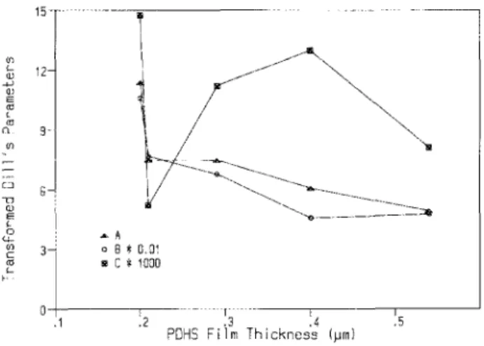
The measured Dill's values of A, B, and C ofPDHS thin
film spincoated on quartz plate are shown in Fig. 1 and indi-cate that their values are irregularly dependent on its thick-ness. The nonlinear photobleaching curves of PDHS with different thicknesses are shown in Fig. 2, from which the Dill's values are measured. The sampling time is 0.5 second in Fig. 2 and the bleaching curves are continuous lines. For the purpose of clarity and comparison with simulated val-ues, only a few data points are shown for each of the five bleaching curves in Fig. 2. The refractive index of PDHS
Q1
:r
'--(l) -'-' OJ E'"
,'"
n 9' I ,f/l , - ,oj
u"
(l) E,
0'-'-"
:-c'"
'--f· .1 • A o 8*
O. a, ~ C*
1080 " '" i .3 .4 .5 PDHS Film Thickness (~m)FIG. 1. Measured Dill's parameters A,B,C are irregularly dependent on PDHS film thickness.
1732 W. Loong and H. Pan: ModeHng of polydihexylsilane as a contrast enhancement material 1732 j ~
Ir~'7'
7~l
.9 .8 .7 f-~ W .6 U Z « .5 f-f- 50 .4 ::;: if) 1: 0.20 ~m Z .3 + « 2: 0.21 ct: 3: 0.29 f- .2 4: 0.40 .1 5: 0.54 r -300 oDD 900 1200 1500 INCl[Jf.N I [JOSE (mJ/cm2 )FIG. 2. Experimental (0, for purpose of clarity) and simulated (--) pho-tobleaching curves ofPDHS with various thickness.
film decreases from about 1.68 down to 1.45 with exposure
doses up to about 240 mJ/cm2 because of the cleavages of
a-bonds ofSi-Si backbones. The automatic modeling and pro-file simulation are impractical for eEL studies in such a case.
An equation was derived to fit these nonlinear
photob-leaching curves {Table 1]. Both thin film transmittance at specific incident doses and transmitted doses can then be calculated. The fitting results are shown as solid lines in Fig.
2. Four parameters, namely P, Q, R, and S are used in this
equation. P is defined as a transmittance change related
rameter before and after bleaching, and is similar to the rameter A of Dill's model. Q is a film thickness related
pa-rameter, R the transmittance of the unbleached film, and S
the slope related parameter at the inflection point of the bleaching curve. Linear relationships were found for these
TABLE I. Equations used for modeling and simulations.
TeD,)
P(l -
~
exp [(D, 1 ] 1/2 ---~-- +R Q)/Sj-" I 'r
D D, =Jo
T(D,)dD, = 2PSln(,11+
e"+
,/':h I~"+
RD" T(D,): film transmittance at D" D,: incident dose, D,: transmitted dose,P: transmittance change parameter, Q:film thickness related parameter, R:transmittance of unbleached film, S:slope related parameter at inflection point,
D, - Q
u~--S~'
uo=~
~ S,
J. Vac. Sci. Techno!.
e,
Vol. 8, No.6, Nov/Dec 1990en '-IlJ -W IlJ E
'"
'-m D-CJ :D"
5 "-UJ c <0 '-f~ ~lor
-~-p*
1O---~ o "*
0.01 8 R*
Ie '" S*
8.1 I? _ ...---FIG. 3. Linear relationships of simulation parameters as a function of thick-ness of PDHS thin films.
four parameters as a function ofPDHS thin film thickness as shown in Fig. 3 within the usually used thickness range for eEL. This equation can apply to different thickness of PDHS film based on this linearity which Dill's model does not take into account.
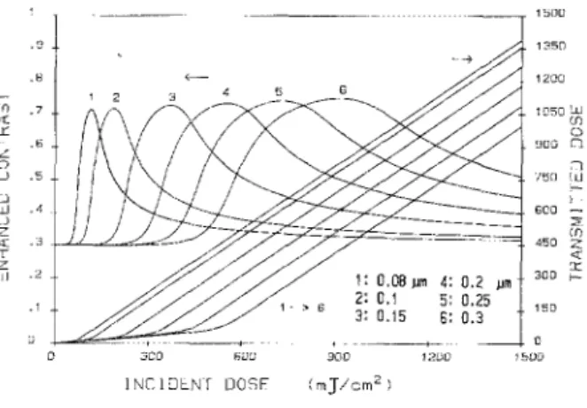
The enhanced contrasts calculated for different PDHS film thickness are shown in Fig. 4 using 0.3 for contrast of the aerial image. Transmitted doses calculated from the de-rived equation are also shown. From Fig. 4, we can find that the enhanced contrast does not improve further with thicker PDHS film. A three-dimensional (3D) plot of enhanced contrast versus different contrast level in the aerial image and dose is shown in Fig. 5. The range of maximum en-hanced contrast becomes much broader for aerial image contrast higher than 0.6. This is certainly an advantage for the process control of exposure dose. The gain is the ratio
-" f-en .7 .-( 0:: f- .0 ;5 U .5 u W .4 U '-<[ .3 T Z 'd .2 :JeD !'01J!] INCIDeNT DOSF + -900 1:WO CmJ/cm2) 1~OO 1~5[] 12C!O 1[150 ':.LJ (f) o ~lOG [')
.,
"/5[) lu 15D j~OOFIG. 4. Simulated curves of enhanced contrasts (using 0.3 for aerial image) and transmitted doses as a function of incident doses for different thickness of PDHS thin films.
1133 W. Loong and H. Pan: Modeling of polydihexylsilane as a contrast enhancement materia! 1733 fi 1 .. thickness: 0.15 i"" .8
...
"'
'"'"
.6 >-z 0 u c Ul u :zi
wFIG. 5. 3D plots of enhanced contrast vs incident doses for various contrasts
of aerial images.
between enhanced contrast and aerial image contrast as il-lustrated in Fig. 6. The results indicate that the gain is nearly independent on its thickness for PDHS. The very high
expo-sure doses (higher than 900 mJ/cm2
) cannot be used
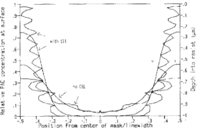
be-cause of the phenomenon ofsclf-development ofPDHS film. For the studies of CEL, the parameters in Table II are used for the simulations of photoactive compound (AZ-135OJ) concentration at the surface of the bottom layer, and
sidewall prOfile (1 !-lm thickness of AZ-135OJ) after wet
de-velopment (Fig. 7), PRO LITH was recompiled and
modi-fied to do the simulations along with the use of the above-mentioned equation. The results of Fig. 7 show that the use ofPDHS as a contrast enhancement layer does improve the sidewall angle somewhat. The dra wback is the need for high-er exposure dose.
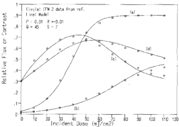
Figure 8 shows that the reported nonlinear bleaching
::>' ::J ::>' X « L z « l'l ~ (f] « n:: ~ z 0 u 5 r
-4.5t
:'5~~
:.~1
2t
"5t
:5
r
. _ -PO~S f;]m thickness A: 0.1511" 8: 0.25/1m L -~-- f-~ -.t---~.---r-~ ----+--- t -o .1 .2 .3 .4 ,5 .6 .1 .8 .9AERIAL IMAGE CONTRAST
FlO. 6. Plots of gains vs contrasts of aerial images.
J. Vac. Sci. Technol. B, Vol. 8, No.6, Nov/Dec 1990
I
-"
TABLE n. Nominal parameters used for CEL modeling and profile
simula-tion. Projection system: Wavelength = 365 nm NA~0.3J5 if ., 0.7 Space - 0.5 lim Pitch = 1.0)tm Defocus,~ 0 CEL parameters: Thickness·c 0.11 iJ.ffi
C (aerial image contrast) = 0.60
C' (enhanced contrast) =' 0.91 Exposure doses ~. 870 mJ/cm" Transmitted doses <c. 300 mJ/cm" P: 0.838 R: 0.130 Q: 140 S: 14.20 p~ 0.127 Xthickncss(pm)
+-
0.824 Q = 2247 X thickness (lIm) - 106.7 R = - 0,()934xthickness(pm)+
0.140 S',~ 95.6 X thickness (/lm) -I 3.682Resist parameters (AZ-1350]): A 0.9,um; B=0.316/lm-1 C c, 0.012 cm1/mJ Refractive index = 1.65 Thickness c-' 1.0)tm Developer conditions: Develop time = 11 s Rrnax ~ 500 nm/s Rrn;n c_ 0.5 nm/s 11 ~ 5.0 mTHc.O.6J
curve ofCEM-2 can be modeled quite well by the use ofthis equation. The values of fitted parameters are also shown. The same equation can also simulate the nonlinear bleaching curves of p-diazo-N,N-dimethylaniline chloride zinc chlo-ride very well and will be presented in another paper soon.
IV. CONCLUSIONS
The parameters of the derived simulation equation are linear with PDHS film thickness within nominal thickness
range ofO.l-O.6pm for eEL. Based on this linearity,
simula-tion of CEL behavior is more accurate than those using Dill's model. The enhancement of contrast seems to be
inde-FIG. 7. Simulated concentrations of photoactive compound (PAC), (AZ-1350J), at surface after exposure, and sidewall profiles after wet develop-ment with and without eEL.
1734 W. Loong and H. Pan: Modeling of polydlhexylsllane as a contrast enhancement material 1734 -'-'
'"
<!J,
-'-' L 0 l ) <-0 x :::J "--'lJ > -'-' m Q) et: .9 .R .7-.5 .5 .4-.j . 2 . 1CinJe: C:fM 2 data fram ref.
line: Model
FIG. 8. Reported (0, data from Ref. 4) and modd simulated (solid line) curves of CEM-2: transmitted flux at maximum (a), at minimum (b); instantaneous (c) and integrated (d) contrast.
J. Vac. Sci. Technol. B, Vol. 8, No.6, NovlDec 1990
pendent of thickness ofPDHS within these ranges. The same equation also fits the reported nonlinear photobleaching curve of CEM-2 quite well.
'F. H. Dill, IEEE Trans. Electron Devices, ED-22, 440 (1975) .
1M. M. O'Toole, IEEE Electron Device Lett. EDL-6, 282 ( 1985).
3c.
A. Mack, J. Vac. Sci. Techno!. A 5, 1428 (1987) .4B. E Griffing and P. R. West, Polym. Eng. Sci. 23, 947 (1983). 5D. C. Hofer, R. D. Miller, C. G. Willson, and A. R. Neurcuther, Proc.
SPIE, 469, 108 (1984).
6S. V. Bahu and E. Barouch, IEEE Electron Device Lett. EDI~-7, 252 ( 1986).