A Scheme to Enhance the Error-Correcting Capability of
Encoded Quantum Information
Han-Wei Wang
∗, I-Ming Tsai*, Chih-Neng Chung*, and Sy-Yen Kuo*
∗ Department of Electrical Engineering, National Taiwan University, Taiwan,
E-mail: sykuo@cc.ee.ntu.edu.tw, Tel.: +886-2-23663577, Fax: +886-2-23688247.
Abstract − In a noisy quantum channel, burst errors
usually causes multiple bit-phase flips that are adjacent to each other [1-2]. This effectively makes some quantum error-correcting codes to be unusable. In this paper, the concept of interleaving qubit transmission is proposed. By using the interleaving method in a quantum information transmission process, burst errors in a quantum channel are re-arranged into different time slots. This relocation makes the error bits non-adjacent and hence increases the probability of information recovery. Note that although this scheme enhances the error-correcting capability of the encoded quantum information, it does not increase the redundancy of the code, because only the qubit sequences are relocated. In addition to the interleaving scheme, implementation of the proposed scheme at the circuit level is also discussed in this paper.
1 INTRODUCTION
Quantum channel coding has been studied extensively recently. The purpose of quantum channel coding is to avoid errors occurred during the transmission of quantum bits. Several quantum error-correcting codes [3-8] have been proposed to prepare the codeword for transmission, but for what happens during the transmission, there is still room for improvement.
Quantum coding methods deal with encoding and decoding bits in the microscopic world. In a microscopic two-level system, one of the eigenstates is denoted as |0>, and the other eigenstate is denoted as |1>. A state can be represented as a superposition of these two eigenstates, and is modeled as a|0>+b|1>, with a and b complex numbers. This means, unlike classical binary logic, these two eigenstates coexist at the same time. Upon a measurement, we can get only one of the eigenstates, with probability |a|2 and |b|2 respectively. Such a
two-level quantum state is described as quantum bit, or qubit for short. In this kind of quantum system, a qubit is represented into the Hilbert space [9] and can be used as an information carrier. Unlike the classical repetition codes, the quantum error-correcting codes are constructed by making a vector in the Hilbert space, instead of making several copies. This is due to the no-cloning theorem that an unknown qubit state can not be copied. As a result, the coding scheme is to map a small Hilbert space into the
subspace of a larger Hilbert space C. For example, the quantum repetition code maps |0> to |000> and |1> to |111>.
However, the problem is that the codeword would be destroyed if a burst error occurs. The classical cyclic codes are developed for protecting burst error. It is based on the linear shifter feedback register. But in a quantum system, the feedback operation does not work. So, we propose the time-spreading and interleaving transmission schemes to protect the burst error using a straightforward construction.
2 QUANTUM COMMUNICATION MODEL
We can consider a simple communication model as shown Fig.1. At the source station, the information is prepared as qubits at the transmitter side and encoded with an encoder. Then the encoded qubits are sent to quantum channel and transmitted to the receiver side. In this model, the quantum channel can be taken as a quantum operation. The errors occur because the noise is introduced from the channel. In the classical world, an error is a bit-flip from 0 to 1 or 1 to 0. However, in a quantum mechanical world, the errors consist of bit-flip, phase-flip, bit-and-phase flip and their linear combinations.
Generally speaking, bit flip means an exchange of the ground and excited state. For example, a bit-flip changes the quantum state a|0>+b|1> to a|1>+b|0>. On the other hand, the phase-flip introduces a rotation along the z-axis in the Hilbert space. A typical example is a 90o rotation from a|0>+b|1> to
a|0>+ib|1>. Usually, a random flip consists of bit and phase flips. Quantum error-correct coding has been developed to protect these errors. However, if only error-correct coding is applied, the information would still get lost with burst errors in the channel. That is because a burst error involves multiple qubits, so usually it can not be recovered by the error coding mechanism.
Figure 1: Communication model.
3 CHANNEL CODING SCHEME
3.1 A simple encoder and decoder
As an example, a simple quantum repetition code is described as follows. In this code, the information of one qubit is encoded into a subspace of three qubit Hilbert space. If error occurs, majority voting can be used to recover the original information. More specifically, the basis |0> and |1> are substituted by |000> and |111>, so an arbitrary state a|0>+b|1> is mapped to a|000>+b|111>. If an error occurs, it can be corrected by simply do a majority voting.
In this method, each symbol is represented using three qubits. If there is no error during the transmission, all three qubits will give the same quantum state after the measurement. If an error does occur, by majority voting, the original quantum state can be recovered if the channel is not too bad. A typical scenario is shown in Fig. 2. First, we copy the quantum state of the first qubit to the second and third qubit by control-not gates. Then these qubits are sent to the destination via the quantum channel. On the other end of the channel, the receiver performs the decoding procedure using three control-not gates. The result is recovered in the first qubit. Notice that, the coding scheme can protect single bit-flip errors. The information will get lost with burst errors.
Figure 2: The encoder and decoder for the quantum repetition codes.
3.2 Old transmission model and drawbacks
Using quantum error-correcting code for information storage and transmission are different. In most cases, the transmission is done from the source to the destination in a parallel fashion. This means the qubits representing one bit of information are transmitted at the same time. A power flash or a
suddenly EM wave will cause a burst of adjacent errors on the channel. As a matter of fact, burst errors occur frequently during transmission.
In the parallel transmission model, a qubit will be encoded as three qubits for transmission. Although they are transmitted via different paths, each qubit is transmitted in the same time slot. In such a case, the noise in one time slot covers three qubits and is actually a burst-error. Because of too many errors occurs in one symbol, the information of this qubit can not be recovered. A parallel transmission scenario is shown in Fig. 3. In the following section, we will propose a coding scheme that is safe against the burst error. The information of coding symbols would be spread to and transmit in different time slots to avoid the burst error.
Figure 3: Original encoding symbol transmission.
4 TIME-SPREADING TRANSMISSION
MODEL
Fig. 4 shows the basic idea of the time-spreading transmission. To spread the information to different time slots, we need to construct the time delay unit in order to store the qubit for transmission. With this scheme, the transmission model is changed form Fig. 1 to Fig. 5. A shifter block is added after the encoder and a de-shifter block is inserted before the decoder. The shifter and de-shifter blocks can be used to perform the time-spreading and recovery operation.
The classical cyclic code for protecting burst errors is generated by cyclic shifter operation that is implemented with linear shifter feedback register. But in the quantum system we can only do straightforward transmission. There is no feedback for the delay unit.
Figure 5: Process of quantum time spreading transmission model.
4.1 Encoding and Decoding
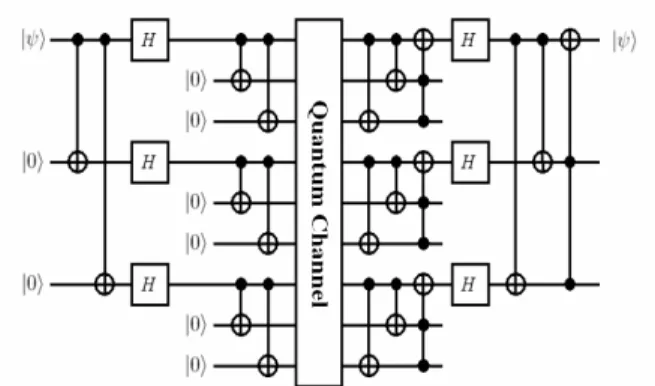
In the following description, we will use a generalization of the repetition code, proposed by Shor, in order to correct bit-flips as well as phase-flips. This quantum error-correcting code uses nine qubits to encode one qubit of information. The encoding circuit is shown in the left of Fig. 6. It transforms the basis of |ψ> into
(1)
Again, the decoding scheme is achieved by majority voting. The implementation of circuit is shown in the right of Fig.6. But if there are more than one qubits get contaminated, the coding scheme does not work. Shor’s quantum error-correcting code corrects bit-flip, phase-flip and a combination of these errors. But only errors on one single qubit can be protected, we need to find another method to protect burst errors. The spreading of codeword comes into play and can be used to enhance its error-correcting capability.
Figure 6: Encoder and decoder of Shor’s code. 4.2 Shifter and delay unit
The idea of a shifter is described as follows. Via the shifter, the qubits of each symbol are relocated into different time slots to protect them against burst errors. It uses the time delay unit to spread the qubit for transmission and achieve the goal of information time-spreading effect. A shifter and its delay unit are shown in Fig. 7.
Figure 7: The architecture of a shifter.
A delay unit is shown in Fig. 8. Two control-not gates are used to swap the quantum information and achieve the goal of delay. In this delay circuit, the input register is set to be |0> initially. Otherwise, three control-not gates with the middle one up-side-down are required. The whole swap operation is performed once at each clock cycle.
Figure 8: Time delay unit. 4.3 Analysis
The burst error correcting capability is defined as the length of consecutive errors that can be corrected. In Shor’s coding scheme, if error occurs on more than one qubit, the coding scheme does not work. So, the ability of burst error correcting is 1 bit. As a result, if we make each delay as two time slots, then the ability of burst error correcting increases to be 2 (with a delay penalty).
We can make the decision of how many time slots we take for each delay by measuring the maximum burst error length of our device. The more time slots for each delay, the more burst error correcting capability the device has. Assume the delay time slots is N, and the number of qubits in each code is M. Then, the delay penalty in total transmission time will be N (M 1)× − , which is a very good bargain.
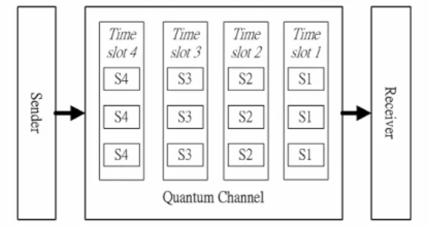
Since a total of nine qubits are used in the code, nine quantum channels have to be used for the transmission. To save the number of quantum channels, the qubits can be sent in an interleaving fashion. For example: If each symbol contains three qubits and the transmitting sequence is (A1), (B1 A2), (C1 B2 A3), (D1 C2 B3). The parallel sequence can be combined into A1, B1, A2, C1, B2, A3, D1, C2, B3, as shown in Fig. 9.
Figure 9: Serialized transmission method.
5 CONCLUSIONS
In this paper, we proposed a generalized concept and example circuits for quantum burst-error-correcting method. In this method, the physical location of each qubit is re-located into different time slots so that the codeword would not be destroyed by burst errors. On the receiving end, qubits are replaced to their original positions using a de-shifter so that any errors that have occurred are spread out. This turns a burst error into a random error which can be easily recovered.
References
[1] F. Vatan, V. R. Raichowdry and M. Anantram, “Spatially Correlated Qubit Errors and Burst-Correcting Quantum Codes”, IEEE Transactions on Information Theory, Vol. 45, pp. 1703-1708, 1999.
[2] M. Grassl and T. Beth, “Cyclic quantum error-correcting codes and quantum shift registers”, Proceedings of the Royal Society London A, 456, pp. 2689-2706, 2000.
[3] Chau H. F., “Quantum convolutional codes”, Physical Review A 58, 905-909, 1998.
[4] A. R. Calderbank, P.W.Shor, “Good quantum error-correcting codes exist”, Physical Review A, 54(2):1098-1105, August 1996.
[5] A. M. Steane, “Error Correcting Codes in Quantum Theory”, Phys. Rev. Lett. 77, 793, 1996.
[6] Markus Grassl, Willi Geiselmann and Thomas Beth, “Quantum Reed-Solomon Codes”, AAECC 1999: 231-244. 1998.
[7] E. Knill and R. Laflamme, “Theory of Quantum Error-Correcting Codes”, Phys. Rev. A 55, 900, 1997.
[8] D.A.L., D.Bacon and K.B. Whaley,
“Concatenating Decoherence-Free Subspaces and Quantum Error Correcting Codes”, Phys. Rev. Lett. 82, 4556, 1999.
[9] Charles Bennett and Peter W. Shor, “Quantum Information Theory”, IEEE Trans. Info. Theory 44, 2724, 1998.