國立交通大學
電子工程學系電子研究所碩士班
碩
士 論 文
用正規描述語言設計與實現
IEEE 802.16d
媒介存取控制層的通訊協定
Design And Implementation Of IEEE
802.16d MAC Protocol Using SDL
研
究 生:莊子宗
指導教授:黃經堯
博士
用正規描述語言設計與實現
IEEE 802.16d媒介存取控制層的通訊協定
Design And Implementation Of IEEE 802.16d MAC Protocol Using SDL
研究生:莊子宗
Student:Tzu-Tsung Chuang
指導教授:黃經堯
Advisor:Ching-Yao Huang
國
立 交 通 大 學
電子工程學系電子研 究所碩士班
碩
士 論 文
A ThesisSubmitted to Department of Electronics Engineering & Institute of Electronics College of Electrical and Computer Engineering
National Chiao Tung University in Partial Fulfillment of the Requirements
for the Degree of Master
in
Electronics Engineering August 2007
Hsinchu, Taiwan, Republic of China 中華民國 九十六年九月
- i -
用正規描述語言設計與實現
IEEE 802.16d媒介存取控制層的通訊協定
學生:莊子宗
指導教授:黃經堯 博士
國立交通大學電子工程學系電子研究所碩士班
摘
要
正規描述語言(SDL)是一個擁有規範及物件導向的語言,我們常用
它來建構即時互動式的系統。由於透過圖像式的描述方式以及可以自動
將正規描述語言的模型轉換成C模型,所以可以有效減少設計的時間。
於是我們採用正規描述語言來當作我們的設計方法學,並以此來實現
IEEE 802.16d 媒體接取控制層(MAC)中基地台的通訊協定。
在本論文中,我們定義 IEEE 802.16 MAC 基地台通訊協定模組架
構,並且描述功能模組化的原因。接著,我們點出了在正規描述語言上
面驗證無線環境傳輸的問題並嘗試用簡化的傳輸方式來解決。 我們採
用了伺服器模型實現此通訊協定並對此模型做優先權、時間管理以及資
料結構的最佳化。最後,針對通訊協定的行為做訊息流程及時間流程的
驗證。
- ii -
Design And Implementation Of IEEE 802.16d MAC Protocol Using SDL
Student:Tzu-Tsung Chuang
Advisor:Dr. Ching-Yao Huang
Department of electronics Engineering
Institute of Electronics
National Chiao Tung University
ABSTRACT
Specification and Description Language (SDL) is a formal
object-oriented language for modeling real-time interactive systems. It
reduces the design time through graphical representation and automatic
translation of the SDL model into C model. For realizing a communication
system, we utilize the design methodology using SDL to implement the
IEEE 802.16d MAC protocol with base station.
In this thesis, we define the BS architecture of IEEE 802.16d Medium
Access Control (MAC) protocol and describe the reasons to modulize each
function of the protocol. To verify the wireless protocol with SDL, we point
out the issue about the transmission behaviors in wireless environment and
provide a simplified method of transmission to solve this issue. The protocol
is implemented based on the concept of the server model that is optimized
by the priority, timer management and data structures. Finally, the behaviors
of the protocol are verified by the message flow and time flow.
- iii -
誌
謝
時間過的很快,剛入學至此兩年的歷程到了終點。初入學之時,感謝老師 黃經堯教 授的收容,才能開啟了自己對於無線通訊領域的摸索,雖然不知日後的發展會否繼 續摸索下去,但是可以慶幸的是,學習的路至此為止雖然走的長了點,卻沒有走偏。 從學習什麼是研究開始,直到現在,過程中一直有著不少的盲點。至此,最重要的 除了感謝 黃經堯老師平日的指導之外,也要感謝老師能夠撥冗參加我的報告,點破 我思考上的盲點,也讓我的研究內容能更趨完整與豐富。除了鄭重的感謝老師們的 指導外,更想要跟一起過日子的朋友們說聲感謝。 首先,就是要感謝實驗室裡面有問必答的學長們,SWAM、文嶽、傑堯、LEMON、 槍A、八屌、域晨、宗奇、俊宇、宗翰及亦琦,因為你們讓我在研究的時候多了很 多的靠山並指引了我很多重要的觀念,再來是陪我一起走過兩年研究的同學、學弟 們,阿虎、小丁丁、玠原、CGI、LC、士恆、家弘、Qmo、宗耿、ARZER、彥甫, 因為你們才能夠讓我在苦悶的實驗室裡得到精神上的歡樂。 再來,感謝我的好友們,路加大隊裡的每位成員,英傑、鉦倫、媚玲、筱媛、秋香、 香穎等…,每次當我無聊要找人歡樂時,你們都義無反顧的挺身而出。感謝中央智 囊團們,KOKA、智超、宏宇、聖偉、育澤、中廷、叔叔,無論身在何方都會無條 件對我伸出援手,讓我不至於流落台北、新竹街頭。感謝mimi7251,多謝你提供我 最大的活力泉源,巧克力。有了你們,才讓我的研究所生活更多采多姿、更加順利。 最後,感謝我的爸媽以及家人,謝謝你們的支持與關懷,沒有你們就沒有現在的我。 2007年 莊子宗撰- iv -
CONTENTS
摘 要 ...i ABSTRACT ...ii 誌 謝 ... iii Contents ...iv Figures...vi Chapter 1 Introduction ...1Chapter 2 Overview of 802.16d system...3
2.1 Fundamentals of 802.16d...3
2.2 PHY Frame Structure...4
2.3 MAC PDU Formats ...5
2.4 Fragmentation and Packing ...5
2.5 QoS Based Service Classes ...6
2.6 Request-and-Grant Mechanism...7
2.7 Network Entry and Initialization of 802.16d...9
2.7.1 Scanning and Synchronization ...10
2.7.2 Acquisition of Downlink and Uplink Parameters ...11
2.7.3 Ranging and Automatic Adjustments ...11
2.7.4 Basic Capabilities Negotiation, Authentication and Key Exchange...12
2.7.5 Registration...12
2.7.6 Establishment of IP Connectivity, Time of Day and Transfer Operational Parameters ...13
Chapter 3 Overview of Specification and Description Language ...14
3.1 Theoretical Model And Structure...14
3.1.1 Definition...14 3.1.2 Theoretical Model...14 3.1.3 Structures...15 3.1.4 Communication ...15 3.1.5 Behavior...17 3.1.6 Summary ...17
3.2 SDL Modeling For Protocol Architecture ...18
3.2.1 Protocol Architecture ...18
3.2.2 TCP/IP Reference Model ...18
3.2.3 Implementation Strategies From SDL...19
3.2.4 Server Model...19
3.2.5 Communication Extended Finite State Machine (CEFSM)...21
Chapter 4 DEVELOPMENT METHODOLOGY FOR COMMUNICATION SYSTEM...26
4.1 Specification Analysis ...26
4.2 Architecture Design ...26
4.3 SDL Modeling ...27
4.4 System Synthesis...28
- v -
5.1 Motivation...30
5.2 Behaviors Correspond To Wireless Environment...30
5.2.1 Transmission Behavior In MAC Layer ...30
5.2.2 Broadcast And Unicast ...31
5.2.3 Contention Period and Contention-Free Period...32
5.3 Architecture Design ...33
5.3.1 WiMAX BS MAC Protocol Model ...33
5.3.2 Data plane...34
5.3.3 Control Plane ...35
5.3.4 Deconcatenation Process...36
5.3.5 Message Management And Control Mechanism Process ...38
5.3.6 UL Scheduler Process...38
5.3.7 DL Scheduler Process...39
5.4 Implementation with SDL ...41
5.4.1 Server Model...41
5.4.2 Timer Management ...42
5.4.3 Message And Data Structures...44
5.4.4 Message And Data Flow ...45
5.4.5 Time Flow ...46 Chapter 6 Conclusion ...48 6.1 Conclusion ...48 6.2 Future Work...48 References...49
- vi -
FIGURES
Figure 2-1 Frame Structure... 4
Figure 2-2 Fragmentation ... 6
Figure 2-3 Packing ... 6
Figure 2-4 Six Steps for a SS to Join The Network ... 10
Figure 2-5 Message Exchanges for Network Entry ... 12
Figure 3-1 SDL Structure-System Block Process Procedure ... 15
Figure 3-2 SDL Communication Interface ... 16
Figure 3-3 SDL Behavior Model-EFSM ... 17
Figure 3-4 The Basic Server Model... 20
Figure 3-5 Basic Component of Server Model ... 21
Figure 3-6 Basic of EFSM... 22
Figure 3-7 EFSM Of Predicate After Action ... 23
Figure 3-8 CEFSM With Timers... 24
Figure 3-9 Translation Of Basic CEFSM Into SDL ... 25
Figure 3-10 Translation Of CEFSM With Predicates After Action Into SDL... 25
Figure 3-11 Translation Of Predicates After Actions Into SDL ... 25
Figure 4-1 RTDS and Project Manger ... 28
Figure 4-2 SDLRT Debugger... 28
Figure 4-3 Rapid Prototyping Design Process ... 29
Figure 5-1 Real World ... 31
Figure 5-2 SDL World ... 31
Figure 5-3 Channel Behavior ... 32
Figure 5-4 BS MAC Protocol Architecture... 34
- vii -
Figure 5-6 Message Management And Control Mechanism Process... 37
Figure 5-7 BS UL Scheduler Process ... 39
Figure 5-8 BS DL Scheduler Process ... 40
Figure 5-9 BS Server Model... 42
Figure 5-10 Timer Management ... 43
Figure 5-11 Message And Data Structures... 45
Figure 5-12 Message And Data Flow ... 46
CHAPTER 1
INTRODUCTION
The communication system we proposed to realize is the standard of Worldwide Interoperability for Microwave Access (WiMAX) [1][2], which promise to deliver high data rate over metropolitan areas to people with different service requirements instead of best effort. The physical (PHY) layer improvements enable selective robustness and efficiency via Medium Access Control ( MAC ) layer negotiation. With the overall Quality of Service (QoS) framework, [3][4] proposes a design approach to implement QoS related architecture.
To investigate the methodology of implementing different protocols, [5][6][7] propose different implementation skills but have the same concept of the implementation in Specification Description Language (SDL)[8][9][10]. To implement WiMAX MAC, the author proposes a System on PC (SoPC) platform for prototype implementation after automatic translation of the SDL model into a C model. And the authors also implement the protocol of 802.15.3 Ultra Wide Band (UWB) and 802.11 MAC protocol through the design methodology using SDL[6][7]. The author in [11]analyzes the timing constraint, time division multiple access (TDMA) MAC protocol based on WiMAX in SS side and depicts some strategies with the optimization of software and accelerator of hardware to implement the standard.
An object-oriented methodology based on an integrated environment for real-time systems [12] is composed of six phases: requirement analysis, system analysis, system design, object design, implementation and testing. In recently years, there is an advance methodology called ESL to improve the efficiency between the design phase, the author shows a taxonomy for ESL tools and methodologies that combines UC Berkeley's platform-based design terminologies with Dan Gajski's Y-chart work [13].
To model the protocol to the SDL model, [14] represents the dynamic aspect of the software architectures by modeling the asynchronous communication in application specific hardware. The efficiency of the server model which is the implementation model used by a known co-design approaches based on SDL [15][16] present several design patterns for Communicating Extended Finite State Machines (CEFSM) [17] which are useful to model the behavior of telecommunications systems.
Our contribution is to provide a method to implementation the communication system, the BS of WiMAX MAC, using a formal language, SDL. To realize the design, we do the protocol analysis of WiMAX MAC, architecture design, the server model using SDL and the optimizations for the timers and data structure. Finally, we verify the protocol by showing the message flow and the time flow.
The rest of this thesis is organized as follows: In Chapter 2, we introduce the protocol of WiMAX MAC. In Chapter 3 we introduce the basic concept for design using SDL. In Chapter 4, we propose a methodology of a design flow to realize the design of a communication system. In Chapter 5, we provide the architecture design and software implementation. Finally, the conclusion and future work are drawn in Chapter 6.
CHAPTER 2
OVERVIEW OF 802.16D SYSTEM
In this chapter, the overview of PHY and MAC layer of 802.16d are first introduced, the frame structure of OFDMA and PHY slot is briefly discussed. In MAC layer, MAC PDU formats, fragmentation and packing, automatic retransmission request (ARQ), QoS based service classes, request-grant mechanism and network entry are investigated.
2.1 Fundamentals of 802.16d
The IEEE 802.16d is a standard for broadband wireless communication for metropolitan area networks. It specifies two modes to share the wireless medium: Point-to-Multi Point (PMP) and Mesh. In this thesis, we focus on the PMP mode. In the PMP mode, the nodes are organized into a centralized structure where a base station (BS) serves a set of subscribe stations (SSs) within the same transmission range in a broadcast manner.
In an IEEE 802.16d system, the downlink (or BS-to-SS) and uplink (or SS-to-BS) transmissions are scheduled in a frame-based structure that time is partitioned into sub-frames in fixed durations. All the SSs listen to the data transmitted by the BS in the downlink sub-frame. On the other hand, in the uplink sub-frame, the SS transmits data to the BS in a TDMA manner. Downlink and uplink sub-frames are duplexed using either FDD or TDD. SS can be either full-duplexed or half-duplexed.
To meet the QoS requirements of multimedia applications, the IEEE 802.16d standard specifies five different scheduling services: Unsolicited Grant Service (UGS), real-time Polling Service (rtPS), extended real time Polling Service(ertPS), non-real-time Polling Service (nrtPS), and Best Effort (BE).
With these fundamentals, IEEE 802.16d targets to guarantee quality of services in broadband wireless communication in metropolitan areas. To support this target for subscribe services, the SSs should perform capability and requirement negotiation before acquiring services from the BS.
2.2 PHY Frame Structure
The OFDMA physical layer is different from other options. The resource usage is more flexible and efficient than SC and OFDM physical layer because of the two-dimension resource allocation. Besides, it can overcome the multi-path effect by guard interval and the design of equalizer and receiver can be much easier due to orthogonal subcarriers and flat narrow band channels.
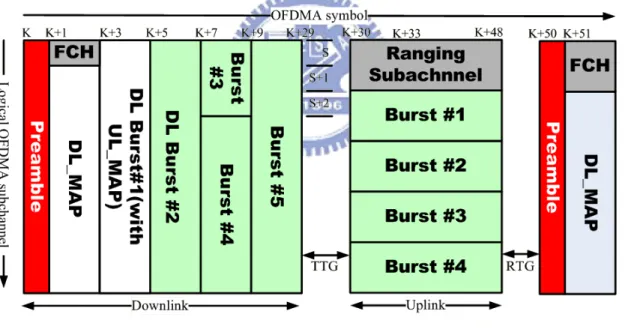
In TDD frame structure, the frames makes system separate downlink and uplink from time index. In Figure 2-1, a frame is divided into two parts. First part is downlink sub frame, it contains preamble, Frame Control Header (FCH), DL_MAP, UL_MAP and DL burst. FCH, DL_MAP, and UL_MAP are used to broadcast control message to each active SS. DL burst is allocated dedicatedly for user data transmission. Second part is uplink sub frame, in uplink sub frame, the ranging channel for network entry procedures and bandwidth request is included. The user can transmit data or may need to feedback-required information to BS in uplink sub frame. Besides ranging channel, there are other control channels in uplink sub frame, such as fast as feedback channel, sounding zone, and etc.
Figure 2-1 Frame Structure
In the beginning of the frame, it is consisted of preamble and some control information. The preamble is used for synchronization. The FCH contains DL_Frame Prefix, and specifies the length of the DL-MAP message that immediately follows the DL_Frame_Prefix and the repetition coding used for the DL_MAP message. The DL_MAP and UL_MAP completely describe the contents of the DL and UL sub frames. The DL_MAP and UL_MAP are used for resource allocation of DL and UL
data bursts, by which the SS can know the required information (modulation and coding schemes, frequency and time shift of the burst).
The UL_MAP also grants bandwidth to specific MSs. Therefore, the MSs can transmit data in the assigned uplink allocation. The DL bursts and UL bursts are used for data transmission of different users. The ranging subchannel is used for initial ranging, periodic ranging, and bandwidth requests. The initial ranging transmission shall be initiated by the SS to synchronize the system channel for network entry procedure.
Different from initial ranging, registered MSs are required to do periodic ranging for system time and power update. Bandwidth requests transmissions are for requesting uplink allocation from the BS. Ranging subchannels are dynamically allocated by the MAC layer and indicated in the UL_MAP. The transmit/receive transition gap (TTG) is a gap between the downlink burst and the subsequent uplink burst. The receive/transmit transition gap (RTG) is a gap between the uplink burst and the subsequent downlink burst.
2.3 MAC PDU Formats
The MAC PDU is a data exchanged unit between the MAC layer of the BS and MSs. A MAC PDU consists of a 48bit MAC header, a variable length data payload, and an optional 32 bits Cyclic Redundancy Check (CRC). Sometimes some MAC PDU will not include payload and CRC bits. These kinds of PDUs are used only in the uplink to transmit control message. Those MAC signaling headers include bandwidth request, uplink transmit power report, CINR report, CQICH allocation request, PHY channel report, uplink sleep control, SN report, and feedback functionalities. MAC PDUs also include some subheaders. Those subheaders will be inserted in MAC PDUs following the generic MAC header. Those subheaders help system perform grant management, packing, ARQ feedback, and etc.
2.4 Fragmentation and Packing
In 802.16d system, MAC SDUs coming from CS will be formatted according to the MAC PDU format in the CPS, possibly with fragmentation and packing. That’s due to the precious radio resources and system hopes to utilize the resources efficiently.
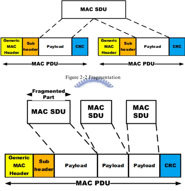
Fragmentation process means to divide a SDU into different PDUs payload areas. That is because the MAC PDU size is limited by standard, 2048 bytes. Besides, larger PDU size may causes error occurs more easily. Therefore, divide SDU properly
according to the channel condition will avoid transmission errors and save the resource used for retransmission. Figure 2-2 shows the process of fragmentation.
Packing process is to pack several SDUs into a single PDU payload. In this way, system may avoid resource waste due to the overhead caused by MAC header and CRC. Figure 2-3 shows the process of packing.
Both processes may be initiated by either a BS for a downlink connection or a SS for and uplink connection.
Figure 2-2 Fragmentation
Figure 2-3 Packing
2.5 QoS Based Service Classes
The WiMAX 802.16d standard provides several QoS classes for system supports different kinds of service. For different classes, system sets different parameters and transmission/request methods to let system maintain the QoS requirement for different kinds of service. Here will introduce these classes:
Unsolicited Grant Service (UGS)
The UGS is designed to support real-time service flows that generate fixed-size data packets on a periodic basis, such as T1/E1 and VoIP without silence suppression. There are several parameters used for this service: Maximum Sustained Traffic Rate, Maximum Latency, Tolerated Jitter, Uplink Grant Scheduling Type and the Request/Transmission Policy.
Real-time Polling Service (rtPS)
The rtPS is designed to support real-time service flows that generate variable size data packets on a periodic basis, such as moving pictures experts group (MPEG) video. It is used for VBR service. There are several parameters used for this service: Maximum Sustained Traffic Rate, Minimum Reserved Traffic Rate, Maximum Latency, Uplink Grant Scheduling Type, and the Request/Transmission Policy.
Extended Real-time Polling Service (ertPS)
Extended rtPS is a scheduling mechanism that builds on the efficiency of both UGS and rtPS. The Extended rtPS is designed to support real-time service flows that generate variable size data packets on a periodic basis, such as Voice over IP services with silence suppression. The parameters are Maximum Sustained Traffic Rate, Minimum Reserved Traffic Rate, Maximum Latency, and the Request/Transmission Policy.
Non-real-time Polling Service (nrtPS)
The nrtPS is designed for non-real-time service that can tolerate more delay, such as FTP, web-browsing, etc… There are several parameters used for this service: Maximum Sustained Traffic Rate, Minimum Reserved Traffic Rate, Maximum Latency, and the Request/Transmission Policy.
Best Effort Service (BE)
BE service is with the lowest QoS level. These kinds of service are designed to support data streams for which no minimum service level is required and therefore may be handled on a space-available basis. The mandatory QoS service flow parameters for this scheduling service are Maximum Sustained Traffic Rate, and Request/Transmission Policy.
2.6 Request-and-Grant Mechanism
The Request-and-Grant mechanism is different form QoS classes because of their characteristics and requirement.
In downlink, it is much easier to handle these procedures. BS has the precise information about traffic requirement. Therefore, BS can easily allocate bandwidth to downlink traffic. There is no need to do request and grant. BS will do everything. In uplink, it is more complicated to do request-and-grant.
MSs use Request to indicate the BS that they need uplink bandwidth allocation. The Bandwidth Request message may be transmitted during any uplink burst, except during any initial ranging interval. In the message right of sending the size of opportunities will be requested.
The Bandwidth Request message could be controlled through polling mechanism. Polling is the process by which the BS allocates to the MSs bandwidth specifically for the purpose of making bandwidth requests. SS can be polled individually, that is called unicast polling. MSs can also be formed into a group and polled together, that is called multicast polling or broadcast. It is used when the bandwidth is insufficient for unicast polling. Besides polling, some SS get bandwidth through contention in the ranging subchannel. Only if SS contents successfully, they can get bandwidth to transmit.
After BS receives bandwidth request message, BS will allocate bandwidth to MSs according to their request if possible. However, some services may get uplink transmission bandwidth even if they do not send request message. This kind of service called Unsolicited Grant Service. System will allocate transmission opportunity in a constant period for users to transmit.
After introducing the Request-and-Grant mechanism, the mechanism used for different QoS classes:
Unsolicited Grant Service (UGS)
SS is prohibited from using any contention request opportunities for this connection. BS assigns resource to SS to transmit in an unsolicited way in a prescribed interval. The BS shall provide unicast grants in an unsolicited manner. Real-time Polling Service (rtPS)
The service offers real-time, periodic unicast request opportunities, which meet the flow’s real-time needs and allow the SS to specify the size of the desired grant. If SS needs uplink transmission, it will send request message in the opportunities polled by BS. SS is prohibited from using any contention request opportunities for that connection.
Extended Real-time Polling Service (ertPS)
The BS shall provide unicast grants in an unsolicited manner like in UGS, thus saving the latency of a bandwidth request. However, whereas UGS allocations are fixed in size, ertPS allocations are dynamic. The BS may provide periodic uplink allocations that may be used for requesting the bandwidth as well as for data transfer. By default, size of allocations corresponds to current value of Maximum Sustained Traffic Rate at the connection. The SS may request changing the size of the uplink allocation.
This kind of service offers unicast polls on a regular basis, which assures that the service flow receives request opportunities even during network congestion. The BS typically polls nrtPS on an interval on the order of one second or less. The BS shall provide timely unicast request opportunities but SS is allowed to use contention request opportunities.
Best Effort Service (BE)
BE service is with the lowest QoS level. It can’t get resource through polling. It only get resource in the contention way.
2.7 Network Entry and Initialization of 802.16d
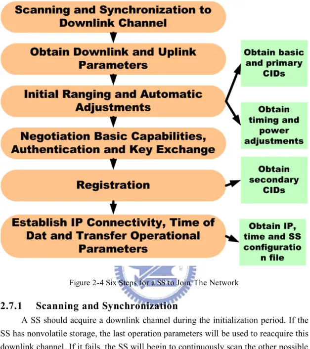
There are six steps shown in Figure 2-4 for a SS to join the network. For each step, there are different purposes as shown in the right boxes in the figure that there are three management connections, basic CID, primary CID and secondary CID, will be maintained through the six steps, scanning and synchronization, obtain downlink and uplink parameters, initial ranging and adjustment, negotiation basic capabilities, authentication and key exchange, registration and establish IP connectivity. By the message exchange using the management connections between the SS and the BS, the SS and BS can communicate with each other with suitable parameters and reliable connections. Later, We discuss the detail processes of network entry shown in Figure 2-4 and message exchange during network entry shown in Figure 2-5.
Figure 2-4 Six Steps for a SS to Join The Network
2.7.1 Scanning and Synchronization
A SS should acquire a downlink channel during the initialization period. If the SS has nonvolatile storage, the last operation parameters will be used to reacquire this downlink channel. If it fails, the SS will begin to continuously scan the other possible channels until it finds a downlink signal in the downlink channel. Then the SS listens to the channel to find the necessary frames without sending anything to the BS.
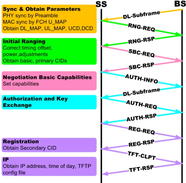
Synchronization could be separated into PHY synchronization and MAC synchronization. When the SS detects the preamble of each frame, PHY synchronization is achieved at the bit-stream level. But the implication of the bit stream is unknown before the MAC synchronization can achieve. The FCH burst followed by the preamble has fixed coding and modulation to point out the following broadcasting MAC control messages especially the DL-MAP message. When the SS receives the DL_MAP message, the associated slot allocation will be informed. As a result, the MAC synchronization is achieved after receiving downlink channel descriptor (DCD) and uplink channel descriptor (UCD) messages. The MAC control
messages are DL-MAP, UL_MAP, DCD and UCD containing in the beginning slot of the frame in order.
2.7.2 Acquisition of Downlink and Uplink Parameters
The downlink and uplink parameters are broadcasted periodically. Each MAP and channel descriptors has a counter number. The earlier the descriptor and MAP are sent, the smaller counter number they have. During the interval that the descriptor with counter number i, the next descriptor with counter number i+1 is also sent to let the SS know the parameters renewed to adjust in the next interval. When the MAP with counter number i+1 is received, the new parameters are used.
The DL-MAP message contains the source BS ID, which the SS can know which BS is synchronized with itself in the downlink channel. The DCD contains the parameters used for the SS to know the downlink burst profile. A SS MAC remains in synchronization as long as it continues to successfully receive the DL_MAP and DCD messages in the downlink channel.
The uplink parameter acquisition depends on the UCD and UL_MAP messages. The UCD messages should be received after the DL-MAP message is received. The UCD message contains the initial ranging and bandwidth request back-off parameters. The back-off values in the UCD message are between 0 to 15. The SS randomly selects a number N within its back-off window that is limited within the back-off parameters as the 2N. The SS will transmit a ranging request message (RNG-REQ) to
the BS in the Nth transmission opportunity. The time slots allowed all MSs to transmit are informed in the UL_MAP, including the allocations. The number of transmission opportunities is informed in the UCD messages. With the UL_MAP messages, the SS knows when to send RNG-REQ to the BS for ranging.
2.7.3 Ranging and Automatic Adjustments
Ranging is the process of acquiring the correct timing offset and power adjustments between the BS and SS. For these two purposes, ranging messages are not only exchanged during the network entry, but should be exchanged periodically when the connections still exist. The SS should set its initial ranging offset to the amount of internal fixed delay.
The ranging request (RNG-REQ) is sent to the BS during an Initial Ranging Interval that is also a contention interval. The CID field is set to the non-initialized SS value (zero). The SS should send the RNG-REQ at a power below the maximum transmission power level. If the SS can’t receive a ranging response (RNG-RSP), it will resend the RNG-REQ at a higher power level unless the maximum transmission power level is reached, and the RNG-REQ will decrease to lower level.
Ranging messages do not only exchange on initialization but also during the normal operation after initialization. Periodically adjusting timing offset and power provides the best signal quality in downlink and uplink channels.
Figure 2-5 Message Exchanges for Network Entry
2.7.4
Basic Capabilities Negotiation, Authentication and Key
Exchange
Each BS or SS supports functions may be different, the SS informs the BS of its available capabilities by sending the SS basic capability request (SBC-REQ) to the BS, then the BS responds with the capabilities set to on of the SS within the SBC-RSP message. And then the SS will authenticate with the BS by exchange some messages.
Registration is the process to allow the SS to enter the network. The SS transmits the registration request (REG-REQ) to the BS. If the SS completes all the initialization messages exchange, the BS will send the REG-RSP containing a secondary management CID for the SS transmitting Dynamic Host Configuration Protocol (DHCP) and Trivial File Transfer Protocol (TFTP) messages and may indicate the IP version. If the IP version is not indicated, the default is IPV4. With the secondary management connection, the SS can get the upper layer management information from the servers in the network and becomes a managed SS.
2.7.6 Establishment of IP Connectivity, Time of Day and
Transfer Operational
ParametersA managed SS will invoke the DHCP mechanisms to obtain the IP address and obtain the time and other transfer operational parameters from time server and TFTP server through the secondary management connection. After completing all the parameter adjustments, the SS will transmit a TFTP complete (TFTP-CPLT) massage to the BS. And then the SS will transmit the dynamic service addition request (DSA-REQ) to request to setup the provisioned service flows. The downlink service connection will be maintained just after the DSA-RSP is sent from the BS and the uplink service connection will be maintained just after the DSPACK is sent from the SS. Besides, the dynamic service addition is possible to be requested by the BS. All the messages exchange between the BS and the SS during the initialization process are shown in Figure 2-5.
CHAPTER 3
OVERVIEW OF SPECIFICATION AND
DESCRIPTION LANGUAGE
This chapter discusses the applications and method for the use of specification and description language (SDL). Recent years, the size of produced software has increased dramatically. More and more systems are multi-process and distributed, and they execute in a heterogeneous environment. It is increasingly accepted within a steadily growing range of industrial segments that the best way to meet the needs of these systems is through formal methods. Therefore, the formal methods should be internationally standardized. Telecommunications software engineers have developed such methods and tools for the development of complex real-time software.
3.1 Theoretical Model And Structure
3.1.1 Definition
Specification and description language (SDL) is an object-oriented, formal language defined by The International Telecommunications Union– Telecommunications Standardization Sector (ITU–T) as recommendation Z.100. The language is intended for the specification of complex, event-driven, real-time, and interactive applications involving many concurrent activities that communicate using discrete signals.
3.1.2 Theoretical Model
The basic theoretical model of an SDL system consists of a set of extended finite state machines (FSMs) that run concurrently. These machines are independent and communicate each other with the discrete signals. An SDL system consists of the following components: 1) Structures like system, block, process, and procedure hierarchy. 2) Communication signals with optional signal parameters and channels or signal routes. 3) Behaviors like processes. 4) Data structures like abstract data types.
3.1.3 Structures
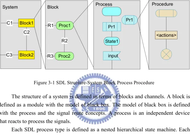
In SDL system, we divide a system into a system, block, and process hierarchy is called partitioning a system depicted in Figure 3-1. The objectives of partitioning include the following:
• Hide information and move the detail into lower level. • Create a correspondence with software.
• Reuse the existing specifications.
Figure 3-1 SDL Structure-System Block Process Procedure
The structure of a system is defined in terms of blocks and channels. A block is defined as a module with the model of black box. The model of black box is defined with the process and the signal route concepts. A process is an independent device that reacts to process the signals.
Each SDL process type is defined as a nested hierarchical state machine. Each sub-state machine is implemented in a procedure. The procedures can be recursive and they are local to be a process or they can be globally available depending on their scope. SDL processes have separate memory spaces. This is a highly important aspect that dramatically reduces the number of deficiencies and increases robustness.
3.1.4 Communication
SDL does not use any global data. SDL has two basic communication mechanisms. The first is asynchronous signals and the other is synchronous remote procedure call. Both mechanisms can carry parameters to interchange and synchronize information between SDL processes and the SDL system with the environment.
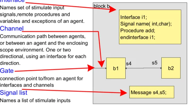
Figure 3-2 SDL Communication Interface
In Figure 3-2, SDL defines a clear interface between blocks and processes by means of a combined channel and signal route architecture. This communication architecture with formally clear signal interfaces simplifies large team development and ensures consistency between different parts of a system.
SDL defines time and timers in a smart and abstract manner. Time is an important role in all real-time systems and also in most distributed systems. An SDL process can set timers that expire within certain time periods to implement timeout events when exceptions.
When an SDL timer expires, the process that started the timer receives a notification in the same way when it receives any other signal. Actually an expired timer is treated exactly as a signal. SDL time is abstract that it can be efficiently mapped to the time of the target system as an operating system timer or hardware timer. This makes it possible to simulate time in SDL models before the target system is available. Other aspects of the signaling concept in SDL are as follows:
Signal and process priorities are not within the scope of SDL. These issues are left instead to the implementation phase where the user with special directives can assign signal and process priorities. An SDL signal can only be sent to one specific process instance at a time. To enable broadcasting the user can include a package with some general-purpose functions that will provide a broadcasting mechanism in the implementation.
3.1.5 Behavior
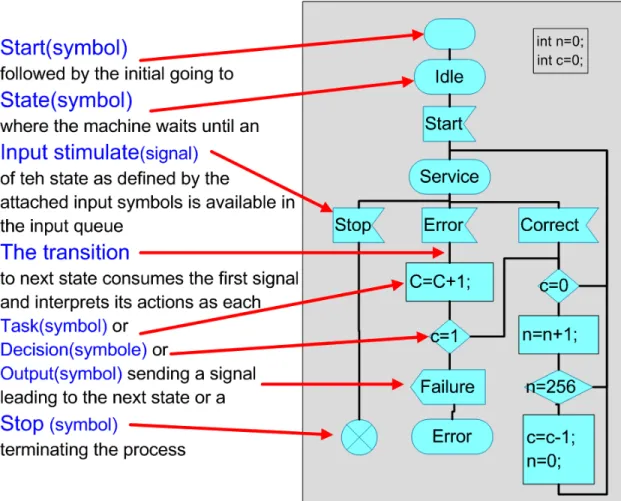
A process itself is specified as an extended finite state machine (EFSM, Figure 3-3) that consumes incoming signals and in turn produces output messages. The behavior in an SDL system is described in the processes. The system/block hierarchy is only a description of the system structure. Processes in SDL can be created at system start or created and terminated at run time. More than one instance of a process can exist. Each instance has an unique process identifier (PId). This makes it possible to send signals to individual instances of a process. The concept is that the processes and process instances that work independently and concurrently.
Figure 3-3 SDL Behavior Model-EFSM
3.1.6 Summary
SDL is a modem high level programming language using object-oriented and graphical design approach that has been used for modeling, simulation and verification of communication protocols for a long time. Especially, SDL is particularly useful in realization of a real-time, interactive and distributed system.
System is described as several processes running simultaneously and communicating via asynchronous signals. Each process is viewed as extended finite
state machine (EFSM) that consists of a number of states and transitions. The state transitions are triggered by receiving a signal from other process with an input queue. During the state transition, the data manipulation and computation may be executed. Timer event can also be configured to generate signals automatically at pre-defined period. A FIFO (First-In- First-Out) input buffer in each process is used to queue the received signals and also the timer events.
The hierarchical structure of SDL system allows the decomposition of a large system into blocks and processes. Signal exchanges between blocks are through channels, and from one process to another via signal routes. A process may contain lowest level components in the functional hierarchy, known as procedures. Hierarchical structure is important for modularization in protocol stack design. Each smaller process and block can be separately developed, verified, implemented, and maintained as individual components. The resulting protocol structure is extendible and reusable.
3.2 SDL Modeling For Protocol Architecture
3.2.1 Protocol Architecture
Communicating systems, especially communication protocols, are the most complex systems to develop. In addition, the tight performance requirements of communicating systems have a major impact on the development of systems. Thus, performance engineering plays an important role in the development of the systems. For these reasons, and because communicating systems are the prevailing application area for the formal description technique SDL, we focus on communication protocols and protocol architectures rather than giving a general description of the design and implementation of parallel and distributed systems.
The communication protocols are highly critical from the performance viewpoint. The performance of parallel and distributed systems is highly influenced by the efficiency of the protocol implementation, the design and the selected protocol mechanisms. Many of the problems and the strategies described here to improve the performance of protocol implementations are also applicable to parallel and distributed systems in general. In order to support this, we concentrate on general issues of protocol design and implementation rather than going into the very details of communication networks.
3.2.2 TCP/IP Reference Model
The TCP/IP model is a descendant of the ARPANET sponsored by the US Department of Defense. A major design goal of the TCP/IP model was to support communication in the presence of failures of some links or hardware components.
Thus, reliability and fault-tolerance have been major issues. Unlike the OSI reference model, the TCP/IP model is less generic and more specific about the services provided. The TCP/IP model focuses on the following layers:
Application layer comprising application-oriented higher-level protocols, supporting file transfer (FTP), terminal emulation (TELNET), electronic mail (SMTP), domain name services (DNS), transfer of hypertext (HTTP), and other services.
Transport layer comprising two important protocols, namely TCP (Transmission Control Protocol) that supports reliable connection-oriented communication, and UDP (User Datagram Protocol) supporting unreliable connectionless transmissions.
Data link layer providing point-to-point connection establishment, error detection and correction, and flow control, Internet layer with the connectionless Internet Protocol (IP) supporting the detection of erroneous headers, routing and forwarding, and segmentation.
Physical layer dealing with the transmission of raw bits over a physical medium
3.2.3 Implementation Strategies From SDL
CEFSM represented in a state transition diagram is easy to understand because it describes the states, the events, and the actions clearly. It can also describe the behavior precisely and formally. The formal description can provide several advantages in the tool support for the patterns and the design evaluation of the initial design made by the patterns. We will show the implementation of the patterns in a specific language SDL. We show that this specific implementation will be helpful with potential to be further reused in a real application.
3.2.4 Server Model
3.2.4.1 Object-Oriented Development Process For Real-Time Systems
The design phase is divided into the system design and the prototyping design. The purpose of the system design is to define implementation structure of the system and identify overall design strategies. The purpose of the object design is to create a complete and formally verified description of the behavior of the system. A set of major rules in the conversion is reported below:
Treat the SDL instances, such as block instance, channel instance and process instance, as objects. Treat the abstract data structures of processes as objects inheriting from the process objects. Represent state transitions and data structure manipulations as object method. Identify common methods between objects to derive a common object that the objects with common methods can be inherited from.
Represent the processes inside a block, or blocks inside a super block as a component of the high level object with aggregation relationship.
Above all, we should understand the system architecture and the conditions of the target environment, and then we could model this design using object-oriented. Afterward we use this concept to set up our knowledge for model the design of communication system.
3.2.4.2 Server Model Basic principles
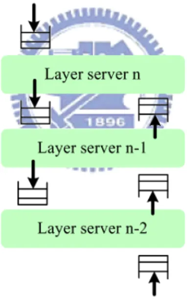
This implementation principle is called the server model. The principle is graphically displayed in Figure 3-4. The server model provides a straightforward mapping of the layered design with implementation. Protocol processing within protocol architecture can be viewed as follows: there are a number of active entities, in the following called servers, each entity implementing a protocol layer or a sub-layer. The servers are asynchronously executing units, communicating with each other through a clearly defined interface. Communication is also asynchronous, employing buffering to decouple sending and receiving entities.
Figure 3-4 The Basic Server Model
3.2.4.3 Implementation of servers
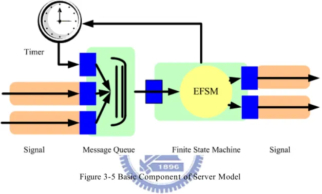
In the server model, each SDL process is implemented as a single RTOS task in SW, respectively as a separate VHDL entity in the HW implementation, with its own message queue. The server model maps each SDL process to one HW. A typical hardware architecture is implemented as one SDL process according to the server model shown in Figure 3-5. One input interface for each communication channel receives SDL messages with the channel's protocol. The message is put at the end of
the queue. The extended finite state machine is implemented in an infinite loop with two nested case-statements. In turn a message is taken from the queue, the transition belonging to message type and process state executed, and, if necessary, a new SDL message is sent via an output channel.
The server model is a straightforward, semantically correct implementation of SDL. While the EFSM part has to be generated for each new SDL model, the message queue, timers, and the entire interprocess communication can be implemented from a library of reusable components.
Figure 3-5 Basic Component of Server Model
3.2.5 Communication Extended Finite State Machine (CEFSM)
When programmers develop software systems, they often find many similar situations that happened in previous developments. A design pattern provides a generic solution for the recurring problems. This is one of the motivations for using design patterns in software development. In other words, a design solution that has worked well in a particular situation can be used again in similar situations in the future. Therefore, design patterns can improve software quality and reduce development time through experience, reusability, and modularity of patterns.
In the early development phases of reactive systems such as telecommunications systems, designers model the desired behavior of a system at an abstract level, and then implement the model in an implementation language. Complex behavior can be obtained by combining simpler building blocks: receiving an event from outside, performing a computation in response to the event, and generating output events.
The patterns describe behavioral patterns both informally and using a formal description technique, communicating extended finite state machines (CEFSMs).
3.2.5.1 CEFSM Definition
CEFSMs consist of a finite set of states and transitions between the states. They communicate with each other via telecommunications paths through signals flow. A CEFSM moves from one state into another by an input event while performing actions during the transition. For a transition, the system must receive an event from environment, and then it performs corresponding actions for the event. After the actions, the system produce output signals if it has something to notify to the environment. We consider deterministic behavior, which means that the system has only one next state for an event.
3.2.5.2 Basic EFSM
A CEFSM can be represented by a state transition diagram that is a direct graph whose vertices correspond to states and whose edges correspond to transitions. Figure 3-6 shows a basic CEFSM and its state transition diagram in which there are two states, S1 and S2, and two transitions. The arrow without a source state points to the initial state S1, and the arrow indicates the initial transition describing the actions and output signals during initialization. Transitions that do not alter the state are indicated by an arc that points to itself. The transition is labeled with an event, action list, and output signals. It is denoted by event (parameters)/actions/outputs. The event may have parameters passing information from other entities. Note that all events except the event of initial transition are mandatory while actions and outputs of transitions are option. The ‘-’ symbol in a transition indicates that there is no corresponding value at that field.
3.2.5.3 Predicates
A CEFSM can have predicates to control the behavior of the CEFSM so that some similar states can be grouped to reduce the total number of states. Upon receiving an event, the machine checks a predicate that is composed of variables, logical operators such as AND, OR, and comparison operators such as equal to, less than, and greater than. If the predicate is true, the entity performs actions and produces output signals if it has something to notify to the outside entities. In short, the CEFSM with predicates decides its next behavior based on the predicates.
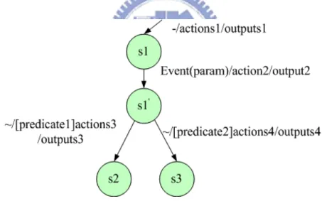
In the CEFSM with predicates, an event is followed by predicates to decide next transition. But in some cases decisions need to be made after performing some actions. In other words, after performing a sequence of actions for an event, an entity decides its next transition depending on the result of the actions. So the entity needs predicates after the actions. Figure 3-7 shows a state transition diagram for this type of CEFSM in which there are four states, S1, S1', S2, and S3. Note that the actions2 and outputs2 of the transition from state S1 to state S1' is followed by the predicates predicate1 and predicate2. The control goes to a transition depending on the result of predicates. Note also that the transitions from S1' do not have an event field.
Figure 3-7 EFSM Of Predicate After Action
3.2.5.4 Timers
A CEFSM can be supplemented with timers and timer-related operations. During a transition, the entity sets a timer with a time value. If the timer is not cancelled by the entity, the timer will generate a time expiration signal after the time duration has been exceeded. Generally, the entity handles the time expiration by either sending an error notification or requesting a resubmission of the event. When an event that is wanted by an entity occurs before the time expiration, the entity cancels the
timer and proceeds normally. There are two timer-related operations, set and reset. Set (v, T1) associates a time value v with a timer T1. Reset (T1) cancels the associated timer T1.
The CEFSM with timers has the same definition as the basic CEFSM except it includes timers and operations for the timers. Timer is an element of variable set. Figure 3-8 shows a CEFSM with a timer and its state transition diagram. During the initial transition, a timer T1 is set with a time value v. On timeout for the timer T1, the entity moves to the state S2 performing actions actions2 and outputting signals outputs2. If the entity receives an event e that is wanted by the entity, it resets the timer and then performs the remaining transition.
Figure 3-8 CEFSM With Timers
3.2.5.5 Translation Into SDL
The translation of a CEFSM into SDL can be done by a mechanical one-to-one mapping. Figure 3-9 shows an SDL diagram fragment for the basic CEFSM of Figure 3-6.The initial transition is converted to a start symbol and a state symbol S1. The initialization actions actions1 and output signals outputs1 are located between them. A transition is represented by an input signal, tasks, and a sequence of output signals of SDL. In the figure, when the state S1 receives an input event with a parameter p, it performs a task actions2 and outputs outputs2. Figure 3-10 shows an SDL diagram fragment for the basic CEFSM of Figure 3-7. Figure 3-11 shows an SDL diagram fragment for the basic CEFSM of Figure 3-8.
Figure 3-9 Translation Of Basic CEFSM Into SDL
Figure 3-10 Translation Of CEFSM With Predicates After Action Into SDL
CHAPTER 4
DEVELOPMENT METHODOLOGY FOR
COMMUNICATION SYSTEM
In our thesis, we integrate much concept of design methodology to implement a communication system, like wireless protocol in MAC layer and provide a design flow to verify our design step by step. The design flow starts with specification analysis based on the protocol that we want to implement. We do some verification for the protocol to guarantee the performance of algorithm. After it, we plan the architecture of the protocol and use functional verification with SDL modeling to verify the system. And then translate the SDL model to C or C++ model.
4.1 Specification Analysis
In our thesis the specification is the protocol in WiMAX MAC. This specification forms the basis for analyzing the system requirements and for the high-level description of the system functionality. From the specification the first high-level formal description is generated. This description depicts systems functionality, in most cases, as a hierarchical mixed data/control flow diagram. System-level simulation or formal verification achieves validation and exploration of algorithms and systems functionality. The purpose of this phase is to analyze the architecture of the system. Essentially the issue of the system analysis is to find out what are the objects needed to implement to meet the requirements of the system.
4.2 Architecture Design
The second step is to refine high-level inter-module communication, including protocol selection. Some design alternatives needed to be identified and need to meet the system constraints. The choices of architecture are made by the user generally. Once the architecture is decided, the functional specification is mapped into an abstract architectural model. This model may include one or more process.
According to the system we want to design, we need to consider many issues, like verification environment, protocol design with communication system and object-oriented and reusable module design. After considering the issues, we start to work out our architecture to achieve the objectives we proposed.
4.3 SDL Modeling
During this part of the design process, the requirements of the analysis are transformed to a formal specification. The formal specification is a full functional specification in SDL. An automated transformation of requirements to SDL leads to an integrated co-design specification in SDL.
Simulation in the phase will help us understand and debug the behavior of our system. The simulator comprises a code generator and a simulator library. The library comes in versions for discrete simulation, real time simulation, and simulation including the system environment.
The main purpose of the SDL is to specify the behavior of systems, which may include the use of data if necessary. First, the logical view describes the functions and services that the system provides to its end users. Secondly, the process view describes the network of independently executing processes that comprise the system, and how they interact and synchronize. SDL specification includes a set of hierarchical block interaction diagrams. Blocks communicate through delaying or non-delaying channels. Each block is defined with a set of SDL processes communicating through nondelaying signal-routes. Each SDL process is an independently executable entity. The SDL flattening function converts the hierarchical block diagrams into one diagram consisting of interacting SDL processes. This flattened SDL system specification diagram provides a process view of the entire system’s software architecture. Third, the physical view describes the mapping of the software components to the hardware. The rule for using SDL to specify software architecture in physical view is to put the processes of different computers on different blocks communicating through delaying channels. Fourth, the development/structural view describes the static modular structure of the software code.
A typical screenshot of RTDS with a SDL system diagram, system organizer and simulator is shown in Figure 4-1 and Figure 4-2. The timing constraints, i.e. deadlines, event streams and event dependencies, are annotated to the SDL specification.
Figure 4-1 RTDS and Project Manger
Figure 4-2 SDLRT Debugger
4.4 System Synthesis
In Figure 4-3, we show an overview of the rapid prototyping design process. And in out design stage, the SDL tool we used is RTDS ( Real Time Development Suite ) that is provided by PragmaDev. The synthesis flow starts with a specification in SDL, using the RTDS for editing, syntax checking and functional level simulation.
After this, Code Generator provided in the tool chain of RTDS translates the SDL semantic to C language or C++ language. In the Code Generator, there are many options of different RTOS ( real-time operating system ) that developers can choose to meet requirement of the target system. Besides, after code generated, we can add some function call coded by hand to the design of C or C++ model. If the design can not meet the requirement, we can optimize the design through buffer management, data management and timer management. Finally, generate the binary code (image) by compiler and linker and then port the binary code to the verification platform, like PC or embedded system.
Through the synthesis flow we can simplify our loading in system level design by Code Generator. And if we have another target platform to port, we can easily translate the SDL to C code according to the RTOS we want to port.
CHAPTER 5
A CASE STUDY: WIMAX MAC BS
5.1 Motivation
Cause the WiMAX MAC BS is complicated in the protocol and the architecture, we need to provide an analysis of protocol and the modulization of the architecture to achieve the module reusable and design effort reducing. Due to the implementation of communication system in detail not considering in previous introduction, we need to develop a methodology to realize IEEE 802.16d MAC protocol by integrating the concepts of SDL, the protocol and server model.
5.2 Behaviors Correspond To Wireless Environment
Due to WiMAX belong to a wireless communication protocol, we could verify the transmission behavior in software and make sure that the behavior in software is the same in wireless environment. According to the protocol in the MAC layer and the behaviors in WiMAX, we add some features to meet the operating requirements in software.
5.2.1 Transmission Behavior In MAC Layer
Considering the implementation of wireless environment, we it is difficult to represent the actual transmission behavior in the software platform shown in Figure 5-1. In order to the SDL implementation, we compare the actual behavior of a system operation and data transmission in SDL wireless environment. According to the specification and concept of SDL, the behavior of such a system is based on software functional verification. But in TCP/IP reference model, we find the data is transmitted from layer to layer in which MAC layer pass the data through PHY layer by channel coding and modulating scheme. Afterward, PHY layer deliver the data to every subscribe station through air medium. Due to our system is to verify the protocol in MAC layer, we will not consider the behaviors in PHY layer.
Base on our assumption, we utilize the concept of transmission between BS MAC to SS MAC in ideal environment shown in Figure 5-2. This assumption can be utilized in the software platform to verify the functions in SDL. We transmit data burst from BS MAC to SS MAC through the simulated channel. Through our proposed channel, we can add some assumption features to make our verification environment more completed. The features we added are about the transmission
behavior in WiMAX such as the transmission behaviors between broadcast and unicast and between contention period and contention free period.
Figure 5-1 Real World
Figure 5-2 SDL World
5.2.2 Broadcast And Unicast
Transmission behaviors in downlink can be separate to two types. One is to broadcast the messages with broadcast CID, 0XFFFF, to all SSs and another is to broadcast data burst of unicast or multicast CID to correspond SSs. The transmission behaviors of the two types in wireless environment are the same due to the broadcasting. But with the software verification, we cannot broadcast the data to all SSs at the same time. So the transmitting data burst using broadcast or unicast are done by software methods. The broadcast in software means copy data to all devices or nodes in proper sequence and the unicast in software means copy data to one device or node. The behavior is shown in Figure 5-3. We can use this behavior on our verification platform to validate the data burst is actually received by two sides. When BS starts to transmit within broadcast period, BS copy data to all SSs. On the other hand, if the BS transmits data burst within unicast period, the BS copy data burst to
correspond SS only. The transmission behavior has some defects for degrading the system performance due to transmit data bursts more times within broadcast period.
5.2.3 Contention Period and Contention-Free Period
The UL sub-frame can be separated into two parts, contention region and contention-free region. The contention region is used to support users for initial ranging and bandwidth request. As the definition of contention, there might have multiple users sending the same CDMA codes simultaneously on the same resource units of the contention region. In that case the collisions will happen so that the requests transmission to BS will be fail. In order to reduce the probability of collision, the back-off procedure is defined in IEEE 802.16d standard, in which when the collision happened, the SSs select a random back-off timer for next transmission. Consequently, the collision probability will be reduced significantly. In contention-free region, each subscribe user will transmit data in the burst assigned by BS in UL_MAP.
For the same reason, the software can’t allow the data burst transmitted at the same time during the contention period. To verify the behavior of detecting collision during contention period, we need to add some tags that not specified in the SPEC. The tag shown in Figure 5-3 is the slot number, which SS predicts to transmit during contention period. Each SSs transmit the CDMA code tagged a slot number to BS through channel. The channel has the ability of collision detecting by receiving the CDMA codes from each SS. When the channel receive the same CDMA codes tagged the same slot number during the contention period, it can determine the CDMA codes are collision and discard the CDMA codes. Or channel passes the CDMA codes of no collision to BS.
5.3 Architecture Design
For MAC protocol design, we provide a guideline to modulize the functions of the protocol. We can briefly divide the functions of MAC into control plane and data plane. According to different protocols in wireless communication, we can partition the functions into some necessary parts and optional parts to modulize the functionality of MAC shown in Figure 5-4. Afterward, we analyze functions of each module to show the flow we proposed.
5.3.1 WiMAX BS MAC Protocol Model
We find the protocol and the architecture of MAC have the same property in wireless communication. Based on the properties and functions in MAC layer, we can divide the properties into data processing and message processing for data plane and control plane.
The data plane deal with the packets fragmented from upper layer to lower layer and the bursts defragmented from lower layer to upper layer. The basic components of data plane are fragment, defragment, assembler and classifier and the optional component are ARQ or other functions provided by other protocol. With our implementation, ARQ is supplement in WiMAX MAC. We can replace the ARQ component with other functions when we apply the architecture to other protocol.
The control plane is responsible for the negotiation with other devices through message passing. To complete the negotiation in MAC layer, there are many functions to go through, like message analysis, producing and flow control. Based on the basic processes of control plane, we divide it into two parts. One is called message management responsible for message analysis and producing, like FCH, DCD, UCD, REQ and RSP. Another is called control mechanism responsible for flow control, like network entry, handover, dynamic service, and timer management. As long as we have some flow control functions that need to add to the protocol of MAC, we can add it to the control mechanism and add some correspond functions of message analyzing and processing to the message management.
Although we can divide the functions of MAC into data plane and control plane, there are still some functions that can’t be divided clearly, like uplink scheduler and downlink scheduler. Cause the two schedulers deal with the bandwidth arrangement for downlink sub-frame and uplink sub-frame and the arrangement involve data fragmentation and messages collection, we need to reconstruct the flow between fragmentation and scheduler to fit the requirement of scheduling policy. So we put the fragment and concatenation together inside the downlink scheduler. On the other hand, to simplify our implementation, we put the uplink scheduler isolated to collect the bandwidth requests and schedule uplink bandwidth. If implementation need, we still
can merge the uplink scheduler and downlink scheduler to do the bandwidth allocation together.
In the end, we show our concept of architecture implementation in Figure 5-4. In later section, we describe the functions of each module with data plane and control plane.
Figure 5-4 BS MAC Protocol Architecture
5.3.2 Data plane
Deconcatenation:This process handles reception of MAC PDUs in form of PHY-DATA from PHY while validating HCS and CRC, and decryption if needed.
Defragmentation_Depacking:
This process extracts MAC SDUs from MAC PDUs with unpacking and de-fragmentation and delivers them to upper layer in form of MAC-DATA. Extracted