Information Processing Letters 45 (1993) 177-183 Elsevier
22 March 1993
On constructing multiple spanning trees
in a hypercube
Feng-Hsu
Wang gnd Ferng-Ching
Lin
Department of Computer Science and Information Engineering, National Taiwan Uniuersity, Taipei, Taiwan, ROC Communicated by K. Ikeda
Received 3 February 1992 Revised 11 November 1992 Communicated by J. Hlstad
Abstract
Wang, F.-H. and F.-C. Lin, On constructing multiple spanning trees in a hypercube, Information Processing Letters 45 (1993) 177-183.
Simple formulas are derived to construct inorder spanning trees in a hypercube network. We identify a routing strategy to ensure the edge-disjointness of the routing paths in executing binary tree algorithms. Large trees can be built in a small hypercube by spreading the load congestion uniformly across the nodes of the hypercube. We also discuss the fault tolerance of the embedding method.
Keywords: Distributed data structure; communication tree; inorder spanning tree; edge congestion; node congestion; fault tolerance
1. Introduction
Tree-like data communication patterns are of-. ten used in multicomputers for designing efficient parallel algorithms, such as broadcast, prefix computation, etc. Due to the bountiful embed- ding capability of a hypercube, numerous commu- nication trees embedded on a hypercube have been explored [1,5,6,101. In this paper, we investi- gate how to construct multiple trees in a hyper- cube for the applications like segmented scan [2,7] and region growing [8]. In the segmented scan problem, the data set is divided into seg- ments and a scan is performed on each segment of data. For the region growing problem, one essential operation is the merging of two consecu-
Correspondence to: F.-H. Wang, Department of Computer Science and Information Engineering, National Taiwan Uni- versity, Taipei, Taiwan, ROC.
tive regions. These applications are characterized by the data mapping scheme that preserves data adjacency for convenient neighborhood commu- nication, and the concurrent tree operations of each data set. The tree operations we consider are special cases of a type of binary tree algo- rithms, called normal algorithms [4], in which only one level of nodes is active at a time.
We aim to propose a distributed data structure for the aforementioned problems. An inorder em- bedding method is especially useful for our pur- pose, which is derived from an earlier result on embedding a complete binary tree based on a grey code mapping scheme with unit expansion and a dilation of 2 [1,51. We generalize the method to embed multiple binary trees, either complete or incomplete, on a hypercube. We first derive simple formulas with only a few addition and bit operations to build a complete inorder spanning tree. Then we present a procedure to build trees
Fig. 1. A binary 3-cube
of arbitrary size. Each processor computes the formulas locally to set up the trees. A routing strategy is identified to make the data routing paths edge-disjoint for normal tree algorithms.
For a practical point of view, it is very impor- tant to address the issues of building large trees on a small hypercube and fault tolerance of the embedding method. Study of these issues on two tree embedding methods are presented in 141. For our method, we show that the load congestion can be spread uniformly across the nodes of the hypercube. We also discuss the fault tolerance of the embedded trees.
2. Preliminaries
An n-cube is an n-dimensional hypercube net- work formed by N = 2” processors. Each proces- sor is represented by an n-bit number. Two pro- cessors are directly connected if and only if their binary representations differ in exactly one bit position. Figure 1 shows a 3-cube. Basic topologi- cal properties of the hypercube are discussed in [ll]. In particular, we are interested in construct-
@ : DataNode ( : Operation Node
I
ing a Hamiltonian path in the hypercube using a grey code indexing scheme. A grey code is a permutation of the ordered set [O, 1,. . . , N - 11 such that the codes of two neighboring items have exactly one bit in difference. (The first and last items are considered neighbors.) There are many ways to generate grey code for different applica- tions. A commonly used one is the Binary Re- flected Grey Code (BRGC) [3]. Let G,(x) denote the n-bit grey code of a number x. It is generated recursively starting with G, = [O, 11. From the grey code
G,= [Gk(O), G,(l),...,G,(2k- I)], the next grey code is given by
G k+, = [OG,(O), 0G,(I),...,0G,(2k - I), 1G,(2k - l), lG,(2k - 2),.. ., lG,(O)]. In the following, unless stated otherwise, we as- sume the codes have n bits and write G,, as G. To store an ordered set of N data items, one can map the ith data item to processor G(i) to pre- serve the data adjacency.
We will use the following notations to facili- tate the presentation. Let anekbk denote the binary bit pattern formed by concatenating n - k a’s and k b’s, where a and b can be 0, 1, or * (don’t care). We use X, to denote the ith bit of the binary number X. We also use +b, l b, @, A z+ 1, A e 1 to represent the operations of
bitwise OR, bitwise AND, bitwise exclusive-OR, shift one bit right and shift one bit left, respec- tively.
Implicit
Volume 45, Number 4 INFORMATION PROCESSING LETTERS 22 March 1993
Two useful lemmas about grey code are listed below.
Lemma 1 [31. G(x) = (x @ (x/2)) and X, = G(x),_,@G(x),_,@ ... @G(x), for O<i<
12 - 1.
Lemma 2 [31. If i > 0 then G(x) and G(x + 2’)
differ in exactly two bits.
3. Embed horder spanning trees
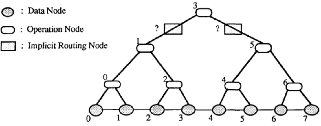
We first consider the problem of constructing a complete inorder spanning tree over the data set [a,,, a,,..., a+ ,I. Some assumptions are made here. Each data item is supposed to know its index within the ordered set, the processor address of the first data item, and the size of the set. Let s be the address of the starting proces- sor, then the data item ai is mapped to processor G(G- ‘(3) + i). Figure 2 illustrates a complete inorder spanning tree to be constructed. In the tree, a node labelled i represents the processor to which the data item ai is mapped. Depending on their functions, the nodes in the tree are catego- rized into three types. A data node is to store a data item. An operation node may perform com- putations or pass results. The operation nodes form an inorder tree with respect to their node labels. A special processor called implicit routing
node is needed to connect the operation nodes on
a two-hop edge. Notice that the data nodes are used as operation nodes or implicit routing nodes also. What we have to do is to construct each edge efficiently, including computing the source and destination node labels of each edge and determining the implicit routing node if neces- sary.
In the complete inorder tree of 2” - 1 opera- tion nodes, there are totally IZ levels indexed from bottom to top by 0 to IZ - 1. In level 1, there are 2”-1-1 nodes indexed from left to right, be- ginning with 0. The label of the root node is 2”-’ - 1, and all the labels of leaf nodes are even numbers. Let k be the label associated with the operation node located at the jth position of
level 1. It can be shown that k = (2j + 1)2’- 1 [9]. By induction on the height of the tree, it can be shown that the labels of the parent, left child and right child of node k are 2’+*lk/2’+‘1+
2/+1 - 1 k - 2’-’ and k + 2’-‘, respectively. To
complete the description, we define the label of the parent of the root to be - 1. Given a node k, if we can compute the value of 2’ efficiently, it will become easy to know the labels of its parent and children.
Theorem 3. Let Pk, LC, and RC, be respectively
the labels of the parent, left child and right child of a node k in a complete inorder tree, and let X = k
+ 1. Then
2’=(X@k) @((X@k) ZQ l), Pk=(k+h(X@k)).h(21+),
LC,=k-(2/N), RC,=k+(2’>1).
Proof. If k is even, node k is in level 0 of the inorder tree. It is obvious that 2’ = (X@ k) @ ((X
@k)% I>= 1, and Pk=(k+,(X@k)).,(2’+‘)
= (k +b l)q,( Y*Ol) = 4[k/4J + 1,
LC, = k, RC, = k + 1. If k is odd and node k is
at the jth position of level 1, then k = (j + 1)2’ - 1. Since X= k + 1, we have X@k = O”-lP’l’+’ and 2’=(X@k)@((X@k)B 1).
It is now easy to compute the values of Pk,
LC, and RC,. By the inorder property of the tree, Pk = 2’+‘[k/2’+*] + 2’+’ - 1. By investigat- ing the binary representation of Pk,, we can con- clude that it must have the form
k ,_,k,,_2.. . k,+,Oll . . . 11. I+i
So, Pk = (k +,, (X@ k))o,(2 >. At last, we can also derive that LC, = k - (2’ * 1) and RC, = k
+(2/z+ 1). 0
The following two lemmas are useful for con- structing an incomplete inorder spanning tree and for studying the fault tolerance capability of the tree.
Lemma 4. In a complete inorder tree, suppose node k in level 1 is reachable from node r by first traversing along the right edge of node r and then traversing along subsequent left edges, then k = r + 2’.
Proof. Let node x in level 1, be the right child of node r. Then x = r + 2’~. Since x = k + 2’ + 2’+’
+ ... +2’rP1=k+2’x-2’, we have k=r+2’.
I-
Lemma 5. In a complete inorder tree, suppose node k in level 1 is reachable from node r by first traversing along the left edge of node r and then traversing along subsequent right edges, then k = r
- 2’.
Proof. Let node x in level 1, be the left child of node r. Then x = r - 2’~. Since x = k - 2’ - 2’+’
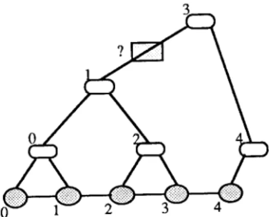
_ . . . -2/x-‘=k-2’1+2’, we have k=r-2’. 0 An incomplete inorder tree is an inorder tree whose left subtree is a complete tree and whose right subtree is an incomplete tree. Figure 3 shows an incomplete inorder spanning tree. Let N’ be the size of the tree. We call a node a “break point” if its left and right subtrees are rooted at different levels, like the root node in Fig. 3. There may be many break points in an incomplete inorder tree. We always traverse along the right-edge way to reach the break points.
Fig. 3. An incomplete inorder spanning tree
Lemma 7. If node r is a break point in an incom- plete inorder tree, then its right child node k is in level 1 = [log(N’ - 1 - r)j. If r f N’ - 1 then k = r
+ 2’; othenvise, r has no right child.
Proof. If r = N’ - 1, it is the last node which, of course, has no right child. Otherwise, since node r is a break point, we can imagine to augment the missing edges from node r to node k that should appear in a complete inorder tree. These edges consist of the right edge of node r and subse- quent left edges. By Lemma 4, k = r + 2’. Since k G N’ - 1 and k is the highest node under node r, we have I=[log(N’- 1 -r)l. 0
Now consider a data set of arbitrary N’ items which is mapped by the BRGC scheme to con- tiguous processors with the starting address s. To build an inorder spanning tree over the N’ pro- cessors, each processor first independently com- putes the labels of its neighboring operation nodes using the formulas in Theorem 3. Since the tree may be incomplete, each processor should per- form a range checking on the labels computed to ensure the integrity of the tree. When a non-root node k at level 1 finds the label of its parent greater than N’ - 1, by Lemma 4, the label of its parent is set to be k - 2’. Similarly, if node k finds its right child out of the range, by Lemma 7, it resets the label of its right child to be k + 21’“g(N-1-k)l if k # N’- 1; otherwise, reset its right child to be k itself. Note that the inorder spanning tree remains to have dilation 2, because the difference between the two node labels of an edge is still a power of two. The actual processor address corresponding to a node labelled m is computed by G(G-‘(s) + m).
To build multiple inorder spanning trees is easy. We can map the data sets to consecutive segments of processors and build an inorder spanning tree for each data set using the afore- mentioned method.
4. Routing in communication trees
Since the constructed inorder spanning tree has a dilation of 2, the choice of implicit routing
Volume 45, Number 4 INFORMATION PROCESSING LETTERS 22 March 1993 nodes is important for avoiding edge conflict in both cases, there exists a unique number z be- data routing. The following theorem can be used tween x and y such that G(z) differs with both to decide the implicit routing nodes for all edges G(x) and G(y) in one bit. Specifically, if x,-, = 0
of dilation 2. then z =x @ (2’ - 1); otherwise, z =y (33 (2’ - 1).
Theorem 8. Let y =x + 2’, i > 0. There exists a unique number z such that x <z < y and both G(x) and G(y) dff I er with G(z > in one bit. Specif- ically, if x,_, = 0 then z =x @ (2’ - 1); otherwise, 2 = y CB (2’ - 1).
Proof. Let x,,:~, denote the bits x,, x,+,, . . . , x,,. Since y -x = 2’ and i > 0, there exists a bit j such that j 2 i and
x=x n-l x 1z-2'~~X,+l Oll...lx,_ I... x,,, Y =Y,l_,Y,_*...Y,+,loo...oY ,-,..‘Y,,7
For a node x to communicate with its neigh- boring node y in the spanning tree, if nodes x
and y are one hop away, no implicit routing node is needed. Otherwise, node x computes the im- plicit routing node as described in Theorem 8. The routing rule ensures the communication in- tegrity of the spanning trees. That is, their com- munications do not interfere with each other. In the following, we analyze the node and edge congestion for the normal tree algorithms.
where x,~,:~- ,, =Y[,,:;-,I and x[,+,+I] =ytj+,:,-11.
Corollary 9. All implicit routing nodes harle even labels. By Lemma 1, G(x)=G(x).-,G(x),,-2...G(x)j+,G(x), 100...0G(x);_,G(x),_,...G(x),,, G(Y) =G(y),,~,G(y),,-,...G(y)i+,G(y), 100...OG(y),-,G(~)i~,...G(~)o, where G(x)~,,:;+~, = G(y),,,:j_l,, G(X),j+ ,:,,-,] = G(Y),j+,:n-,I) G(X), = G(y),, and G(X);_,
= G( y),_ ,. In addition, either G(x);-, = x,_, or G(y);-, =x,_, must hold.
Since G(x) and G(y) differ in two bits, there are two numbers that differ with both G(x) and G(y) in one bit. Let G(s) and G(t) be the two numbers, then
Proof. Let node z be the implicit routing node of an edge which is of dilation 2 and connects two operation nodes x and y. Then x and y are both odd and their difference is a power of two. By Theorem 8, both (2 OX),, and (z @ y),, are 1. Since both x and y are odd, z must be even. q Corollary 10. An implicit routing node r can only appear in the unique path from the root to the leaf operation node r in the inorder tree.
G(s) =G(x),,~,G(x).-,...G(x)j+,G(x)j
100.. .OG( x)~_ ,G( x);-~. . . G( x),,, G(t) =G(x),,-,G(x).-,...G(x),+,G(x),
100...OG(x);_,G(x)i~~...G(~),~. By Lemma 1,
Proof. By Corollary 9, node r is a leaf operation node of the inorder spanning tree. By Theorem 8, the implicit routing node r may occur only in those edges connecting two operation nodes whose labels encompass r. In an inorder tree, the edges that encompass r are those comprising the binary search path for r in the tree. The search- ing path is just the path from the root to the leaf operation node r. q
s=x nplXn-2..'Xj+l 0111.. . 1x;_,xi&2.. .q), t =x,_Ixnp 2”. xj+,looo...ox,_,xi_,...x,,.
Therefore,ifx,_,=Othenx<s<yandx<y<
t. If Xi&, =l then s<x<y and x<t<y. In
Corollary 11. Let s be the starting address of a processor segment. Suppose r is an implicit routing node and x is a non-leaf operation node. Then the communication channel connecting processors G(G-‘(s) +x) and G(G-‘(s) +r) may be used only in the edge connecting x and its parent and the edge connecting x and one of its children.
Proof. Node x has only three edges incident on it, one to its parent, and two to its children. By Corollary 10, it is impossible that an implicit routing node r occurs in both x’s child edges. However, node r may be encompassed by node x and its parent node. So, the communication chan- nel connecting processors G(G-i(s) +x> and G(G-i(s) + r) may be used by at most two edges in the inorder tree, one connecting x to its par- ent and the other connecting x to one of its children. 0
Since the segment spanning trees act without interference to each other, analysis of a single tree is enough. In a normal tree algorithm, only one level of processors is active at a time. Due to Corollary 11, no node or edge congestion is in- curred.
5. Constructing large trees and fault tolerance
As concerning the fault tolerance of the in- order spanning trees, we first consider the fault tolerance capability against the leaf (operation node) failures. If only one leaf descendent fails, the parent will perform the task of the faulty leaf. If both leaf descendents fail, the two nodes la- belled next to the corresponding faulty leaves will replace them. Since the two replacement nodes differ by 2, they are still two hops away. With this leaf replacement scheme, the trees can tolerate a small fraction of leaf failures with a little slow- down, which is due to the missing of some im- plicit routing nodes.
Suppose there are t inorder spanning trees of Assuming no leaf failures, the embedding sizes N,, N2,. . . , N, to be constructed on a hy- method provides effective fault tolerance against percube with P processors, where P < N, + N2 internal node failures. Suppose x is a faulty in-
+ . . + +N,. We present a very straightforward ternal node. If x is a left descendent, the right allocation scheme in which the load of each pro- child of x is used to replace x. On the other cessor is averaged. First allocate to each spanning hand, if x is a right descendent, x can be re- tree a number of physically contiguous processors placed with its left child.
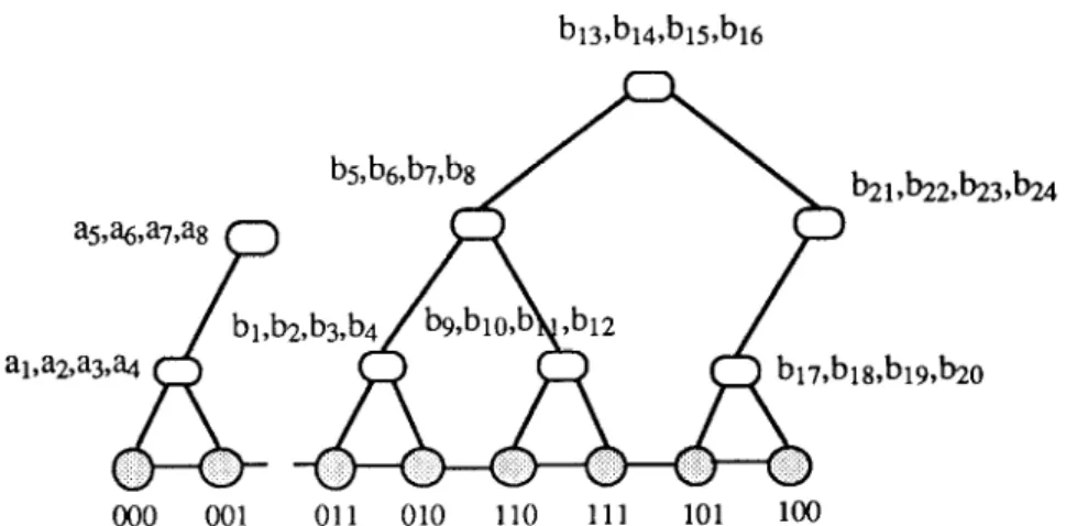
proportional to the tree size. Then, each tree stores its data items in a consecutive storage scheme to the processors allocated to it, and an inorder spanning tree is constructed on the pro- cessors using the method described previously. Figure 4 illustrates the construction of two trees A and B of sizes 8 and 24, respectively, on a
hypercube with 8 processors.
Fig.
000 001 011 010 110 111 101 loo
Volume 45. Number 4 INFORMATION PROCESSING LETTERS 22 March 1993
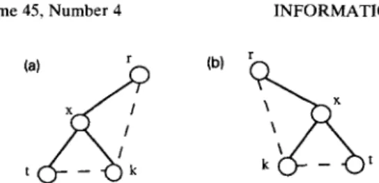
Fig. 5. Replacement scheme for internal node failures. (a) Replacement for a left-child node x. (b) Replacement for a
right-child node x.
Theorem 12. The replacement scheme for internal nodes preserves the dilation of the embedding at 2. Proof.
Let node r be the parent of the faulty
node x which is at level I and node
kbe the
selected node for replacement. If node x is a left
child of node
r(Fig. 5(a)) by Lemma 5, node
kand node r are two hops away. Similarly, if node
x is a right child of node
r(Fig. 5(b)), by.Lemma
4, node
kand node
rare two hops away. In both
cases, node
kis two hops away from the other
child node r of X, since the difference of their
labels is 2*.
q6. Concluding remarks
We have presented an efficient, actually con-
stant-time, construction of segment inorder span-
ning trees on consecutive data sets in a hyper-
cube. This data structure is well suited for seg-
mented scan and image processing problems in
which data are mapped to contiguous processors
for convenient neighborhood
communication.
It
is also shown that our routing strategy is edge
congestion free for normal tree algorithms. The
issue of constructing large trees on a small hyper-
cube is solved straightforwardly.
Replacement
scheme for fault tolerance is presented. In addi-
tion, since the tree sizes can be arbitrary, our
results can be extended to incomplete hypercube
easily. Position flexibility is another advantage of
the inorder trees, so we can devise a relocatable
distributed data structure for fault tolerant paral-
lel computing.
References
[l] S.N. Bhatt et al., Optimal simulation of tree machines, in: Proc. 27th Ann. Symp. on Foundations of Computer Science (1986) 274-282.
[2] G. Blelloch, Scans as primitive parallel operations, in: Proc. Internat. Conf on Parallel Processing 2 (1987) 355
362.
[3] R.M. Chamberlain, Grey codes, fast Fourier transforms and hypercubes, Parallel Comput. 6 (1988) 225-233. [4] K. Efe and R. Kumar, Congestion and fault tolerance of
binary tree embeddings on hypercube, in: Proc. 5th Inter- nat. Parallel Processing Symp. (1991) 458-463.
[5] S.L. Johnson, Communication efficient basic linear alge- bra computations on hypercube architectures, J. Parallel Distributed Comput. 4 (1987) 133-172.
161 S.L. Johnson and C.T. Ho, Optimum broadcasting and personalized communication in hypercube, IEEE Trans. Comput. 38 (9)(1989) 1249-1268.
[7] C.P. Kruskal, L. Rudolph and M. Snir, The power of parallel prefix, IEEE Trans. Comput. 34 (10) (1985) 965- 968.
[8] W.L. Marc and P.R. Anthony, Solving nonuniform prob- lems on SIMD computers: case study on region growing, J. Parallel Distributed Comput. 8 (1990) 135-149. [9] A. Moitra and S.S. Iyengar, A maximally parallel balanc-
ing algorithm for obtaining complete balanced binary trees, IEEE Trans. Comput. 34 (6) (1985) 563-565. [IO] 2. Mu and M.C. Chen, Communication efficient dis-
tributed data structures on hypercube machines, in: Proc. Second Conf on Hypercube Multiprocessors (1986) 67-77. 1111 Y. Saad and M.H. Schultz, Topological properties of