Design
And
Implementation of a Microprocessor-Based
Intelligent Electronic Meter
M.-F.
Lai
and
Y.-P.
WU
Department of Electrical EngineeringNational Taiwan University Taipei, Taiwan, china
ABSTRACT
This paper presents the design and implementation of a microprocessor-based intelligent electronic measuring apparatus. The meter can measure instantaneous values of
voltage, current , and power of electrical power distribution system. A novel random asynchronous sampling technique that samples voltages and currents at predetermined intervals is exploited Using the proposed random asynchronous sampling technique, the circuit complexity can be reduced. Furthermore, the accuracy of the meter is improved significantly by compensation of phaae shift error due to
current transformer (CT). Moreover, the AID quantization error is compensated for low current measurement A
prototype including CT is built to veri@ the theoretical analysis and examine the performance of the proposed system. The proposed meter can be used as a universal electrical meter for both local power consumption indication and computerized power management system.
L INTRODUCTION
The conventional Ferraris induction disk metering based on electromechanical principles have been used worldwide' since 19th century. Recently, the requirements of precision measurement, data acquisition, energy mauagement, and communication for modern electricity metering have stimulated the idea to develop intelligent meters based on electronic and microprocessor techniques. Several electronic metering systems were presented previously [ 11
-
[6]. Kinston and Woolner developed a combined Wzr and Vmb poly-phase meter based on mark-space-amplitude (MSA) multiplier technique [l]. Hun and Fielden proposed a wholly digital microelectronics meter based on CALMS (Credit and Local Management System) technology 121. Ropnan presented a static watt-hour meter based on Hall&ea
131. Summers utilized wersampled A/D conversion technique to develop an integrated meter for remote telemetering applications [41. Hill described a low-cost microprocessor-based wattmeter for the measurement of power from a sinusoidal source [5]. Triger proposed the concept of a universal digital meter using a sampling technique [6].However, most existing electronic metering system have the following disadvantages: high circuit complexity, large error for low current measurement, inherent power measurement error due to phase shift of current transformer (CT) or potential transformer
0.
This paper proposes a microprocessor-based intelligent meter, inG.-C.
Hsieh
and
J.-L. Lm
Department of Electronic Engineering National Taiwan Institute of TechnologyTaipei, Taiwan, china
which the error for low current measurement due to A/D
quanthtion is improved, and the power measurement error due to the phase shift of CT is compensated by software technique.
JJ. SYSTEM BLOCK DIAGRAM
The functional block diagram of the proposed meter is illustrated ip Fig. 1. The meter consists of the following major blocks: Transducers (CT and FT), Phase leadflag detector (ZCD circuits), sample-and-hold (S/H 1
-
S/H 3) circuits, multiplexer0,
A/D converter (ADC), and microprocessor ($). In our system, the input voltage (110 Vrms f l P ? ) is attenuated by a resistor divider (with attenuation ratio of 1/34) to produce a voltage of +_ 5.0 V (peak-to-@), which is suitable for the processing of subsequent S/H and A/D converter stages. A resistor divider is used as PT (potential W o r m e r ) in our design. The CT used in our system provides the conversion ratio of 0.025 VIA. Two amplifiers with voltage gain of Avl = 10 and Av2 = 5 are employed. to amplify the output signal from CT.Fig. 1 Functioaal blodcdiagrm
The phase leadflag detector is composed of two zero- crossing detectors (ZCDs). One ZCD is employed to detect the zeroaxsing point of voltage waveform, the other ZCD to detect the zerocrossing point of current waveform.
The S/H is an analog voltage storage device in which an input voltage is sampled and then stored on a capacitor. The sampling rate, opemting at 481 sampledsec, is generated by the timing circuit in the microprocessor. The 481 Hz timing signal is used to control S/H from the "sample" state to the "hold" state. The input voltage which
occurs at the time of "hold" command is retained for subsequent A/D conversion.
The multiplexer is employed to provide time sharing of Assume there are M samples per second, and the an A/D converter among a number of different analog sampled voltage and current values are v k and Ik
to the input channels of the multiplexer. OW input follow^: channel is selected at a time for connection to the
multiplexer output by the command from microprocessor. HI, SYSTEM OPERATION PRINCIPLE An electronic meter needs to measure the electrical parameters such as voltage. current. and power. etc. Measurement of the true ms r a h e for lnstanlaneous
voltage and current usng traditional analog method becomes diflicult lfthe input waveform LS non-sinusoidal or
distorted sinusoidal [7]. The &@tal sampling method is a good alternative to solve this problem. A number of sampling techniques, such as real time sampling, asynchronous sampling, and random repetitive sampling, are aviulable. A novel random asynchronous sampling technique, illustrated in Fig. 2, is utilized in this paper. The sampling occurs asynchronously with the input signal being measured. Tlus sampling method captures data on the input waveform by acquiring sampling points on more than one cycle of the input signal. On each occurrence of the trigger event, a few more points in one input signal cycle are acquired after waiting a predetermined amount of time from triggering point. The predetermined time interval is incremented for each successive input cycle. After a number of cycles, the waveform is reconsbuded from all the sampled points. Tlus sampling technique alleviate speed ~ n t s o f h a r d w a r e , ami thus circuit complexit?. can be reduced si-. Assume the frequenq of input signal and sampling frequency are fm and fs respectively, then the total sampling points in one cycle (pass) will be fJ./f,. From Fig. 2, the number of samples per second is fs, and the time interval between two consecutive sampled point for successive cycles is lUJm second. ‘ < . & I x x x x I x’ x 4 X X X x .x
Fig. 2 Random aq”u sampling technique
I.-=\I“-
M(3) 1 M
Pq =- E v k I k k=l
The digitizing error (E) due to sampling of M samples in
the period from t = 0 to t = T can be calculated as follows
181.
2 24k -1)
-Xsin2--
M k=l M (4)
A phase shit2, denoted by a , exists between the secondary current and primary current of a CT. Assume the phase angle between voltage and current is 8 , then the power error (sP) between the measured power (P,) and true power (Pt) is found to be
E,, = P,-e =cosa-1-sinatan0 ( 5 )
Form
(3,
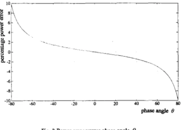
it is obvious that the power error becomes large when 8 is close to 90”. The relationship between the power error and the phase angle 8 at the phase shift of a= 1’ is shown in Fig. 3.
1-.
.‘%O -M -40 -20 0 20 40 80
phaseangle e
Fig 3 Power error vexsus phase angle 0
In our system, the error compensation due to phase shift in CT is based on the following formulas [SI.
1)
e
> o ( ~ i a d s v )2) 8 < O( I l ag sV )
VL
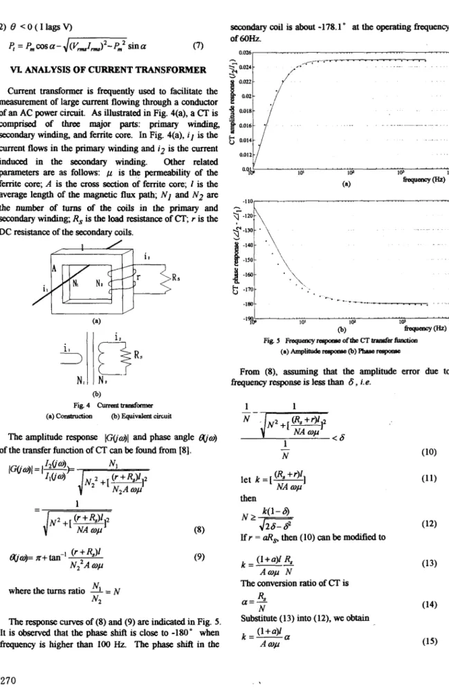
ANALYSIS OF CURRENT TRANSFORMER Current transformer is frequently used to facilitate the measurement of large current flowing through a conductor of an AC power Circuit. As illustrated in Fig. 4(a), aCT
is comprised of three major parts: primary winding, secondary winding, and ferrite core. In Fig. 4(a), il is the current flows in the primary winding and i2 is the current induced in the secondary winding. Other related parameters are as follows: is the permeability of the ferrite core; A is the cross section of ferrite core; 1 is the average length of the magnetic flux path; N I and N2 arethe number of turns of the coils in the primary and secondary winding; R, is the load resistance of
CT;
r is the DC resistance of the secondary coils.The amplitude response
Iwm)l
and phase anglea m )
of the transfer function ofCT
can be found from [ 81.O.Ol*C/
i
-.
L-13 ' " " " " I 0' ' " " " " W ' " " " " IW ' " . . . . J lV
@) (W
Fig 5 F ~ ~ o f t b e C T & c x M o n
(a) Amp-resporrss @) raspollse
From (8), assuming that the amplitude error due to frequency response is less than 6, i.e.
then
Ifr = aR, then (10) canbe modified to
(I+u)l R, k = - -
A m p N
(9)
The conversion ratio of CT is where the turns ratio = N
N2 a = - Rs
N The response curves of (8) and (9) are indicated in Fig. 5 .
It is observed that the phase shift is close to -180" when
(13) into (12), we Obtain
(l+u)l A WP
a -
V. DESIGN CONSIDERATIONS
The analysis and design consideration of CT have been discussed in previous Sectioa The design cwsiderati on for electronic circuitry and mimpmxsa operahon are
presented as follows.
* Avoltagedivi~rmadeoftworsiston(RjandR6)with
a attenuation of appro- 3Ye is to convert 171 V to 5 V for A/D au"
= = 0.02924
& + &
17W 16)l l ~ capaator d t a g c m ampleand-hold circuit
in
the 'hold' mode at r = ' 1 , IS1 - 1 , -3
v , ( t ) = V # - z +Y(l-e x ) (17) where v,(O)= 0,and y(r)=
L;
for the sa"gThe time a"(r) dtk anant should be The sealing time for voltage follower used in the output interval from f l to
r2
selectedas r>5RCinor&rtoobtainmrlessthanl%. of multiplexex is 2 F m f, =-
SRwhere f Fm is the full scale voltage of
AID
converter, and 2Fm is the maximum output voltage swing of voltage follower.The resolution of the AID converter can be de&xmkd as follows. Assume the mini" input voltage to
AID
converter is by 'Fp @o.Ol-O. 1 for normalbits number (Q) of A D COlIvertQcau be found from the applicarion),andthenquircd~aawacyby e . Then
following equation.
The m i c r o p m r is the heart of the electronic meter. The random asynchronous sampling method, the computation algorithm are all r e a l i d by microprocessor
soilkare.
Intel
875 1 &bit " r o l l e r has been chosen m our design to &agn a c O s t 4 h i v e electronic meterwith less component lxnulls.
VL PROTOTYPE DESIGN
A prototype IS built to venfy the performance of the
proposed system. An deuronic meter including CT which implemented: full scale voltage VF = 120V (rms); full scale current IF = 2OA (peak); mput signal frequency at 60
Hz +_ 3 Hz; voltage ~ccuracy at 1% (from 0 . 1 V ~ to VF);
current acarracy at 1% (from 0 . l l ~ t o IF); power accuracy a t 2 % ( h m 0 . 0 1 I ~ t o I ~ a t llOV).
can meet the fouowmg specifications is to be designed and
In
our system, aCT
with conversion ratio of a=O.O25VlA, accuracy of 6 = O.l%, and frequencyresponseoff> 60 Hz is tobedesigned:
A ferrite core TDK H5cuEE28 is chosen, which has the following parameters: relative permeability b= 1oooO; core area A = 38.4 "2; core length I = 53.88 mm. Substitute above parameters into (1 5), we can calculate the value of k.
k=- a=10.6( l+u) (20)
A
Qw
With accuracy requirement of 6 = O.l%, and substitute thisvalue into (14). we obtain
(2 1) k(1-6)
N > G 7
F m (20), (21) and U = 1, we obtain N > 348. TbereforeN=400isselected. S i n c e N 1 = 1 isusedinour From (14) a = R, / N. Since a =0.025, N = 400, we desig&weobtainN2=4ooturns. haveRs= 10R .
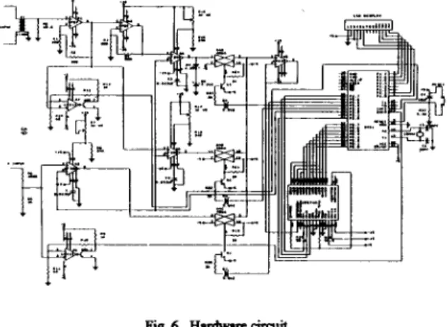
2. Hardware DesignThe design consi&rations described in Section V are used as a guideline for circuit design. The complete hardware Circuit is illustmted in Fig. 6. The design of each block is explained as follows:
In order to obtain 0.25 V/A and 1.25 VIA from CT, a 2-
stage amplifier using OW7 is designed with gain of A,,] =
10 andAv2 = 5 .
Fig 6 HardwarrcircUit
From (16), a voltage divider (R5, R6) with attenuation ratio at 1/34 is used. In order to meet condition of power c~IlSumption I ~ S S than O.lW, Rg and R6 can be f-d as Rp3536
R
and Rc117464R
.
We choose R5=3K, Rc100K in our design.1. CT Design
LF398 IC is chosen to design S/H Circuit. R7 (lK,
VR),
R8 (24K) are used to adjust offset voltage. With sampling time at 1Wps and the condition of 'F > 5RC, thecapacitance value of the holding capacitor is chosen as C>%. Since R = 30021 inside LF398, we obtain C > 0.0167 ,u F. A capacitor of C = 0.0333 ,u F is selected.
LM3 11 comparator IC is used to design ZCD Circuit (A6 & A7). Rg'lK, R l r l O K , Rll=268
n
are selected to provide hysteresis voltage of 30 mVm
our design.CD4066 IC (A4) is used as analog multiplexer. The output of A4 is c o ~ e ~ t e d to a voltage follower designed by LM3i8 (A5). The output of A5 is applied to an AID converter.
The required bits number of A/D converter is determined by the conditions of error ( E S WO), and minimum voltage input at 0 . 1 V ~ m . 1 ) . From (19), we have Q 2 10. Therefore a 12-bit successive approximation A/D converter IC (AD574A) is selected.
5R
W
EXPERIMENTALRESULTS
The test d t s of the prototype is shown in Fig. 7. The rms voltage measurement result is indicated in Fig. 7(a). It is observed that the error is less than 0.5% for input voltage less then 30V. The rms current measurement result is indicated in Fig. 7@), in which the error is less than 0.5% for the input current less
than
1A. For current input lessthan
0.684 the error increases rapidly.The average power measurement result is indicated in Fig. 12(c). The error result for power factor at PF=1, P F4.6 (lead), and P F 4 . 6 (lag) are indicated, respechvely. It is observed that the error of power measurements is less
than
2% for power fixtor ranged fiom 0.6 (I leads V) to 0.6 (Ilags0.
IX. CONCLUSION
An intelligent meter using electronic and microprocessor4ased'technique has been designed and implemented. Using the random asynchronous sampling method, the circuit complexity is reduced. Furthermore, the system accuracy is improved significantly due to compensation techniques exploited for error due to phase shift and low current measurement. Moreover, the functons of the intelligent meter are confgurable by software; this provides the flexiiility for adding Merent metering applications. The proposed system can be expanded to include data acquisition and commuuication capability to faciltate precise control of power consumption for efficient energy management. Based on the proposed hardwidsohare architecture, a high performance intelligent meter can be built costeffectively.
[ l ] G . A K i ~ @ l t ~ a a d L W o ~ l a a , " M ~ l t i F u n d i O a P ~ l ~ M d e r i o g -
An htcgmtd AppmadP, Sixth International Cogerence on Meeting Apparalua and Tar@ for Elecfrjcity Supply, unaed KingQm, Apil
1990, pp. 62
-
66.[2] P. R Hutt aad J. S. Fielden, "Mgg BeaeMs sod Flexibility in Intelligmt Mdaing tcdmology, Sixth International Confsence on
Meeting Apparatus and Tat@ for Ekclncity Supply, united KingdaR April, 1990, pp. 67
-
72.[J] M. Romys " A static Domestic W n t t b Based on Hall E€Fects". Sixth
Memational Conference on Meeting Apparatus and Tariffs for
Electricity Supply, uoaed Kingdom, Apris 1990, pp. 107
-
110. [4]R Sunmux4 "hkgmtd Somioooduda Solutioos faMetaiOg andTebmtaing Applicatioas", Sixth International Confrence on Meeting Apparalua and Tmffa for Elecm'city Supply, Unitcd Kingdas ApriL
[5] W. Hi& "Low cost M i a q " Based W a U " , IEEE,lnstrument andMeusurement Technical Confwence, Bouldu, U. S. A, Mar., 1986. [6]L Triga, "Ibc U n i v d Electricll U&, IEEE Instrument and
Measurement Technical Confirence, Boulder, U. S. A , Mar., 1986. [7)R Turgel. "Digital Wattmda using sampling Method", L E E
Instrument and Measurement Technical Conference, vol. IM-23, W. 4, Dec., 1974.
[8]G. C. H a i 4 "Rescarcb 00 Power Transduar", T & d Reporf N a t i d Taiwan InstiMe of Technology, Dec., 1993.
[9] S. Chhmmi, Physics OfMagnetIsm, J. Wdcy Savia, New Y& 1964.