A Latency and Modulation Aware Scheduling Solution for IEEE 802.16
Base Stations
Yuan-Chih Chang, Chen-Hua Shih, and Yaw-Chung Chen*
Department of Computer Science, National Chiao Tung University,
Hsinchu 30010, Taiwan
*Department of Computer Science and Information Engineering
Asia University, Wufeng, Taichung 41354, Taiwan
[email protected], [email protected], [email protected]
Abstract
-The mobile worldwide interoperability for microwave access (WiMAX) system provides high data rate, wide bandwidth for wireless network. However, the link quality is unstable owing to air interference and long-distance transmission. When link quality change, mobile node can revise the modulation and coding scheme (MCS) dynamically. Thus, we propose a modulation-aware scheduling solution for WiMAX base station (BS). It contains three primary methods: an admission control scheme (ACS), a scheduling algorithm, and a bandwidth allocation scheme. In addition to MCS, we also take latency for real-time service into account.The proposed admission control scheme calculates the admission condition based on different kinds of MCS and minimum reserved rate requirements. The modulation aware scheduling algorithm and bandwidth allocation scheme can allocate bandwidth more efficiently in the finite frame duration and guarantee the minimum quality of service (QoS) requirements to each admitted connection by translating the QoS requirements into time slots. Finally, our simulation results show that the proposed scheduling solution can improve the throughput of the entire network and guarantee the minimum QoS requirements to each admitted connection. Keywords: modulation aware
,
802.16, WiMAX, QoS, scheduling.1. Introduction
The WiMAX standard based on the IEEE 802.16-2004 [1] and IEEE 802.16e [2] specifies a metropolitan area broadband wireless access network technology. The main advantages of WiMAX are the higher data rate and the longer transmission range. The standard defines two basic operational modes to achieve medium sharing:
point to multipoint (PMP) and Mesh mode. In the PMP mode, a subscriber station (SS) can communicate with other stations only through the BS and thus the BS is responsible for managing the downlink and uplink transmissions and allocating bandwidth for SSs. In the Mesh mode, a SS can communicate with other SSs or BS directly.
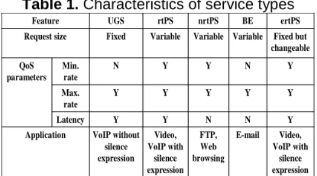
To meet the QoS requirements of multimedia applications, the WiMAX standard defines a QoS signaling framework and five different scheduling service types: Unsolicited Grant Service (UGS), real-time Polling Service (rtPS), non-real-time Polling Service (nrtPS), Best Effort (BE), and Extended real-time Polling Service (ErtPS). The UGS supports real-time data streams consisting of fixed-size data packets issued at periodic intervals, such as VoIP without silence suppression. The rtPS supports real-time data streams consisting of variable-sized data packets issued at periodic intervals, for example, Moving Pictures Experts Group (MPEG) video transmission. The nrtPS supports delay-tolerant data streams consisting of variable-sized data packets for which a minimum data rate is required, for example, FTP. The BE service supports data streams for which no minimum service guarantees are required and therefore may be handled on a best available basis. The ertPS is suitable for variable rate real-time applications that have data rate and delay requirements such as VoIP with silence suppression. Each scheduling service type is associated with a set of QoS parameters to specify its QoS requirements. Table 1 presents the characteristics of five different scheduling service types.
Although the service types and the associated QoS parameters have been well-defined in the IEEE 802.16 specifications, the resource management and scheduling mechanisms for 802.16e BS to guarantee QoS still remain an open issue.
Table 1. Characteristics of service types Video, VoIP with silence expression E-mail FTP, Web browsing Video, VoIP with silence expression VoIP without silence expression Application Y N N Y Y Latency Y Y Y Y Y Max. rate Y N Y Y N Min. rate QoS parameters Fixed but changeable Variable Variable Variable Fixed Request size ertPS BE nrtPS rtPS UGS Feature
Several research works [3, 4, 5, 6, 7] were proposed using complex scheduling algorithm, such as weighted fair queue and worst-case weighted fair queue, and even a hierarchical schedulers. These scheduling algorithms are neither simple in implementation nor concerning the MCS. Besides, it is a difficult task to use a hierarchical scheduler when the frame duration is very brief in time. Thus, we propose a one level scheduling solution considering the QoS parameters defined in 802.16e standard, the QoS requirements of each connection (such as latency requirement, the maximum sustained traffic rate, and the minimum reserved traffic rate), and the adaptive MCS. The proposed scheduling solution contains admission control, scheduling and bandwidth allocation mechanisms. Furthermore we take latency parameter into account for real-time service flow to calculate the deadline of packets.
The proposed scheduling solution possesses several superior characteristics, including modulation and latency aware, implementation feasibility in BS, guarantee of minimum QoS for certain services (UGS, rtPS, nrtPS), and allocating bandwidth efficiently.
The simulation results indicate that the proposed scheduling algorithm can improve the throughput of the entire network and guarantee the minimum QoS requirements to each admitted connection.
2. The Proposed Scheduling solution
The scheduling solution we proposed concerns only the scheduler at the BS that uses TDD duplex in PMP mode. It contains three primary schemes: admission control policy, scheduling algorithm, and bandwidth allocation scheme.
2.1 Admission control scheme
To guarantee the minimum QoS requirement for different kinds of service connections, the admission condition of the modulation aware ACS is calculated based on the minimum reserved rate for each admitted data connection. In the TDD node, the transmission unit in WiMAX system is
symbol whose capacity depends on the MCS. Therefore, when a new frame starts, the required data size/bandwidth request size in downlink/uplink must be translated first to amount of symbol as shown in expression (1):
symbol per bits size data symbols of number _ _ _ _ _ (1)
An OFDM symbol contains 192 data sub-carriers and 8 pilot sub-carriers in WiMAX PHY and the MCS decides the number of bits carried in a sub-carrier. Hence the number of bits per symbol can be calculated as
symbol
per
bits
_
_
8
_
192
efficiency
coding
rate
(2) Where the efficiency and the associated bits_per_symbol for different kinds of MCSs is presented in Table 2.Table 2. The efficiency and the associated
bits_per_symbol for different MCS
MCS Efficiency Bits_per_symbol OFDM_BPSK_1_2 1 bps/Hz 88 OFDM_QPSK_1_2 2 bps/Hz 184 OFDM_QPSK_3_4 2 bps/Hz 280 OFDM_16QAM_1_2 4 bps/Hz 376 OFDM_16QAM_3_4 4 bps/Hz 578 OFDM_64QAM_2_3 6 bps/Hz 760 OFDM_64QAM_3_4 6 bps/Hz 856
The average required symbols per frame for the
ithconnection T(i) based on minimum reserved rate and MCS can be calculated as
_ min( ) ( ) _ _ ( ) BW i FPS T i
bits per symbol i
(3)
Where the BW_min(i) is the minimum reserved rate of the ith connection, and the
bits_per_symbol(i) stands for the bits per symbol
in the ith connection. FPS means the frames per second, and it can be derived as
1 _
FPS
frame duration
(4)
A connection which wants to access the WiMAX network will be allowed when the sum of
T(i) is smaller than the available number of
condition of proposed ACS is presented in expression (5). 1
( )
i nif
T n
avalible symbol in a frame
(5)The modulation-aware ACS can provide a precise scheme to calculate the number of SS which can be admitted. So, bandwidth allocation in scheduling will be more efficient.
2.2 Scheduling algorithm
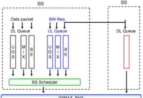
Figure 1 presents the proposed scheduling architecture in WiMAX system. The proposed scheduler uses two directional queues, i.e., downlink queue which deals with incoming data packets from each downlink connection, and uplink virtual queue which deals with bandwidth requests corresponding to the uplink resource demands of SSs. Three kinds of queues were defined in the two directions, referred as UGS, MIX, and BE queue. The UGS queue serves the bandwidth requests and data packets for UGS connections. The MIX queue holds the request and data packets sent by rtPS and nrtPS connections. The BE queue stores the requests and packets of the BE connections. In the uplink, we also need to stores periodic grants and unicast request opportunities for rtPS and nrtPS in the UGS queue.
Figure 1. Proposed scheduling architecture
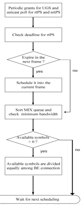
The priority of downlink queue is higher than the uplink queue. Therefore, the scheduling order for all kinds of queues is as follows: first, UGS DL, UGS UL, DL rtPS packets which will expire in the next frame, UL rtPS bandwidth requests which will expire in the next frame, mix DL, mix UL, BE DL, and BE UL. The proposed scheduling order can adjust the DL/UL sub-frame ratio dynamically. The deadline to each packet/request can be calculated through the arriving time of the packets/requests at the SS/BS queue. In the uplink, the BS can not get this information, and the worst
case is considered. This corresponds to the arrival at the queue immediately after the connection sent the last bandwidth request [7]. Thus, in the uplink case, the deadline of an rtPS request is equal to the arriving time of the last request sent by the connection plus its maximum latency. In the downlink case, the deadline of a data packet is equal to arrival time of the data packet plus its maximum latency for the connection. For each packet/request i to rtPS connection in the MIX queue, 1
check_deadline[i] < 2 means packet/request i will expire in the next frame. Thecheck_deadline[i] can be derived as [ ] _ [ ] _ deadline i now check deadline i frame duration (6)
Where now means the current time, and deadline[i] presents the deadline for packet/request i.
To guarantee the minimum bandwidth requirement for rtPS and nrtPS connections in the MIX queue. The BS scheduler sorts the packets/requests in the MIX queue based on the granted bandwidth to each rtPS/nrtPS connection. After dealing with the UGS and MIX queues, the remaining bandwidth will be assigned to the BE queue. Figure 2 represents a simple flow chart for proposed scheduling algorithm.
2.3 Bandwidth allocation scheme
The scheduling algorithm decides the order of different traffics, and the bandwidth allocation scheme calculates the bandwidth allocated for each connection.
2.3.1 UGS queue
The bandwidth allocation to the ith connection for UGS downlink is presented as expression (7).
) ( _ _ )} ( _ ) min( _ ), ( min{ ) ( _ i symbol per bits i bit granted i BW i Qsize i symbol allocated (7)
Where Qsize(i) stands for the queue size in unit of bit to the ithconnection, granted_bit(i) stands for the number of the allocated bits to the ith connection.
The bandwidth allocation to the ith connection for UGS uplink is derived as expression (8).
) ( _symbol i allocated ) ( _ } int _ i T duration frame erval grant (8)
yes
yes no
no
Figure 2. Proposed scheduling algorithm 2.3.2 rtPS queue
The bandwidth allocation to the ith connection for this class downlink and uplink are presented as expression (9) and (10) respectively.
if (granted_bit i <( ) BW_ min( )i )
) ( _ _ )} ( _ ) min( _ , ) ( _ min{ ) ( _ i symbol per bits i bit granted i BW i size packet i symbol allocated
(9)if (granted_bit i <( ) BW_ min( )i )
) ( _ _ )} ( _ ) min( _ , ) ( _ min{ ) ( _ i symbol per bits i bit granted i BW i req BW i symbol allocated
(10) 2.3.3 MIX queueThe bandwidth allocation to the ith connection for the MIX queue downlink and uplink are presented as expression (11) and (12) respectively. if (granted_bit i <( ) BW_ min( )i )
) ( _ _ )} ( _ ) min( _ , ) ( min{ ) ( _ i symbol per bits i bit granted i BW i Qsize i symbol allocated
(11)if (granted_bit i <( ) BW_ min( )i )
) ( _ _ )} ( _ ) min( _ , ) ( _ min{ ) ( _ i symbol per bits i bit granted i BW i req BW i symbol allocated
(12) 2.3.4 BE queueThe bandwidth allocation to the ith connection for BE downlink is presented as expression (13).
} ) ( _ _ ) ( , _ min{ ) ( _ i symbol per bits i Qsize n symbols available i symbol allocated (13)
The bandwidth allocation to the ith connection for BE uplink is derived as expression (14).
} ) ( _ _ ) ( _ , _ min{ ) ( _ i symbol per bits i req BW n symbols available i symbol allocated (14)
Where n is the number of BE connections in which the allocated bandwidth is less than the maximum sustained rate.
3. Simulation and Numerical Results
We use NS-2 (version 2.31) simulation tool [8] with WiMAX NIST module [9] which is originally designed and developed by the National Institute of Standards and Technology (NIST) in U.S.A to simulate the proposed scheme.
Each simulation scenario includes a wired node, a BS, and several SSs with different service flows. The wired node is connected to the BS with a link, whose bandwidth and delay are 1000 Mbps and 1ms, respectively. The bandwidth of this link is larger than the WiMAX network. Figure 3 depicts the network structure for the simulation. In each simulation scenario, the general parameters of the 802.16 network are the same, and they are presented in Table 3.
Figure 3. The network topology for simulation. Table 3. Parameters of simulation scenario
Parameter Value
PHY OFDM
Duplexing mode TDD
Frame duration 5ms
Frames per second 200
Available symbols per
frame 70
DL/UL ratio dynamic
Simulation start time
(second) 10
Simulation end time
(second) 30
Polling interval (rtPS)
(ms) 20
Polling interval (nrtPS)
(ms) 100
The UGS connection is simulated with the constant-rate data sent over the UDP protocol. According to the G.711 audio codec [10], we set the packet size to 160 bytes and the granted interval to 20ms. The rtPS connection is simulated with variable-rate data sent over the UDP protocol. We set the rtPS packet size to 1378 bytes, the maximum sustained rate to 410880 bps, the minimum reserved rate to 205440bps, and maximum latency to 50ms. The nrtPS and BE traffic are generated by FTP application. For nrtPS connections, we set the packet size to 1000 bytes and the maximum sustained rate to 200K bps, the minimum reserved rate for 150K bps. For BE connections, we set the packet size to 200 bytes, the maximum sustained rate to 120K bps, and the minimum reserved rate to 0 bps. Table 4 presents the traffic type and QoS requirements.
3.1 Simulation scenario 1
In this scenario, we analyze the proposed ACS, and general ACS which assumes all SS using the same MCS. We use several rtPS service
connections to test the throughput of ACS. Each SS has one rtPS connections to the BS. There are 20 64QAM_3_4 SSs, 15 16QAM_1_2 SSs, and 10 BPSK_1_2 SSs to randomly access the WiMAX network in our simulation scenario. The General_BPSK_1_2 ACS means that the general ACS assume all SS using the BPSK_1_2 MCS. The meaning of the General_16QAM_1_2 is similar to the General_BPSK_1_2. The simulation result is shown in Table 5.
Table 4. Traffic type and QoS requirements
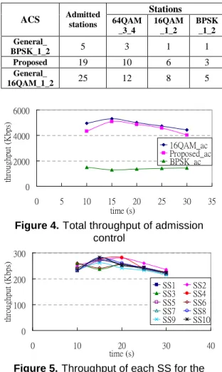
Table 5. Simulation result of admission control
0 2000 4000 6000 0 5 10 15 20 25 30 35 time (s) th ro ug hp ut (K bp s) 16QAM_ac Proposed_ac BPSK_ac
Figure 4. Total throughput of admission
control 0 100 200 300 0 10 20 30 40 time (s) th ro ug hp ut (K bp s) SS1 SS2 SS3 SS4 SS5 SS6 SS7 SS8 SS9 SS10
Figure 5. Throughput of each SS for the
proposed scheme Bandwidth (bps) Service class Traffic type Packet size
(byte) Max Min
UGS UDP/CBR 160 80000 64000 rtPS UDP/VBR 1378 410880 205440 nrtPS TCP/FTP 1000 200000 150000 BE TCP/FTP 200 120000 0 Stations ACS Admitted stations 64QAM _3_4 16QAM _1_2 BPSK _1_2 General_ BPSK_1_2 5 3 1 1 Proposed 19 10 6 3 General_ 16QAM_1_2 25 12 8 5
0 100 200 300 0 5 10 15 20 25 30 35 time (s) th ro ug hp ut (K bp s) SS1 SS2 SS3 SS4 SS5 SS6 SS7 SS8 SS9 SS10
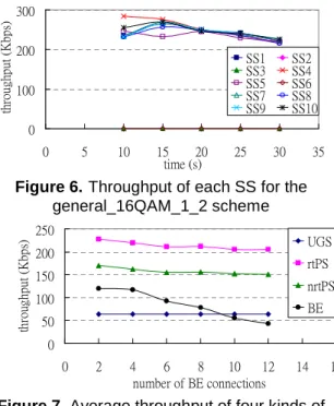
Figure 6. Throughput of each SS for the
general_16QAM_1_2 scheme 0 50 100 150 200 250 0 2 4 6 8 10 12 14 16 number of BE connections th ro ug hp ut (K bp s) UGS rtPS nrtPS BE
Figure 7. Average throughput of four kinds of
service connections
In Figure 4, we can observe the total throughput of general_BPSK_1_2 ACS is about 1400 Kbps. The total throughput of the proposed ACS can achieve at least 4000 Kbps. The throughput of the general_16QAM_1_2 ACS is higher than the proposed scheme slightly. However, the proposed scheme can guarantee the minimum reserved rate requirement for each admitted SS, but the general_16QAM_1_2 scheme can not (see Figure 5 and 6).
3.2 Simulation scenario 2
The goal of scenario 2 is to investigate whether the increase of the BE service traffic load influences or not the QoS level of service which has higher priority. For this purpose, the simulated scenario includes one BS and 32 SSs. There are 4 UGS connections, 8 rtPS connections, 8 nrtPS connections, and the number of BE connections varies from 2 to 12. The UGS, rtPS, and nrtPS connections use 64QAM_3_4 MCS. The BE connections use 16QAM_1_2 MCS.
As we can observe in Figure 7, the average throughput of the rtPS and nrtPS connections decreased slightly as the BE connection increased. The average throughput of the UGS is always 64 Kbps. The proposed scheduling solution can guarantee the minimum reserved rate (64, 205.44, 150 Kbps) requirement to UGS, rtPS, nrtPS connections even though we increase the BE traffic load. Furthermore, we also guarantee the
maximum sustained rate (120 Kbps) requirement to the BE connections. Since the BE connection has no minimum reserved rate requirement, the average throughput decreased as the traffic load of whole system increased.
4. Conclusions
In this work, we take latency and MCS into account in our scheduling solution. The proposed scheduling solution contains three primary components: an admission control scheme, a scheduling algorithm, and a bandwidth allocation scheme. Some properties of our proposed scheduling solution are as follows: modulation and latency aware, being implemented in BS easily, guaranteed minimum QoS requirements for certain specific services (UGS, rtPS, nrtPS), and allocating bandwidth efficiently.
The simulation results show that the proposed admission control scheme can admit the suitable number of SSs to help the scheduler guarantee the minimum reserved rate to each admitted connection.
References
[1] IEEE Std. 802.16-2004, “Local and Metropolitan Area Networks, Part 16: Air Interface for Fixed Broadband Wireless Access Systems,” Oct. 2004. [2] IEEE Std. 802.16e-2005, “Local and Metropolitan
Area Networks, Part 16: Air Interface for Fixed and Mobile Broadband Wireless Access Systems,” Dec. 2005.
[3] J. Chen, W. Jiao, and H. Wang, “A Service Flow Management Strategy for IEEE 802.16 Broadband Wireless Access Systems in TDD Mode,” IEEE
International Conference on Communications, Vol.
5, 2005, pp. 3422-3426.
[4] K. Wongthavarawat and A. Ganz, “IEEE 802.16 Based Last Mile Broadband Wireless Military Networks with Quality of Service Support,” IEEE
Military Communications Conference, Vol. 2, 2005,
pp.779-784.
[5] G. Chu, D. Wang, and S. Mei, “A QoS Architecture for the MAC Protocol of IEEE802.16 BWA
System,” IEEE International Conference on
Communications, Vol. 1, 2002, pp. 435-439.
[6] M. Hawa and D. W. Petr, “Quality of Service Scheduling in Cable and Broadband Wireless
Access Systems,” The 10th IEEE International
Workshop on Quality of Service, 2002, pp. 247-255.
[7] J. Freitag and N. L. S. Fonseca, “Uplink Scheduling with Quality of Service in IEEE 802.16 Networks,”
IEEE GLOBECOM, 2007, pp. 2503-2508.
[8] http://www.isi.edu/nsnam/ns/
[9]http://www.antd.nist.gov/seamlessandsecure/downloa d.html
[10] Pulse code modulation (PCM) of voice frequencies, ITU-T recommendation G.711, 1988