High Dynamic Range Display Adopting High
Dynamic Range Imaging Technique
Yu-Kuo Cheng
Dep’t of Photonics and Inst. of Electro-Optical Eng., Nat’l Chiao Tung Univ., 1001 Ta Hsueh Road, Hsinchu, Taiwan Yu-Wen Wan and Han-Ping D. Shieh
Dep’t of Photonics and Display Inst., Nat’l Chiao Tung Univ., 1001 Ta Hsueh Road, Hsinchu, Taiwan Abstract- Technique of high dynamic range imaging (HDRI)
was introduced into conventional high dynamic range display (HDRD). Sharpness of image was further enhanced by improving local contrast ratio in the HDRI-based high dynamic range display.
I. INTRODUCTION
Display systems displaying images with high dynamic range (HDR) of luminance, e.g. beyond 50,000:1, were first proposed by Brightside Technology [1-2]. The display system, shown in Fig. 1, is composed of a liquid crystal (LC) panel and a backlight system with light emitting diodes (LEDs) as light sources. The display physically shows high dynamic images without using traditional computer graphic techniques.
Image sharpness, i.e. local contrast of luminance, is an issue while the global contrast is achieved amenably using the aforementioned HDR display (HDRD). As shown in Fig. 2, intensity enhancement (step 2), down-sampling of resolution (step 2a) and convolution (step 4) all contribute to the lost details of image, albeit using adjusted LCM signal (step 5) to refine images. Plausible methods to deduce both sets of LED and LCM signal, steps 3 and 6 respectively, are needed.
Multi-scale decomposition of image in high dynamic range imaging (HDRI) was reported to extract details from image [3-5]. Referred to the method proposed by Frédo Durand and Julie Dorsey [5], the concept of base, detail and color layers can be extended to HDRD application. LED signals are deduced from de-convolution process with the base and detail layers, and then the color layer is coped with to define the LCM signals.
Fig. 1. HDRD system structure.
I I 11 I 22
( )
L 1 1 I r− 33 L 1 I p ⊗ 44 L 1 I p I ⊗ 5 5 ⊗ − L 1 1 2 p I I r 66 LED LED LCM LCM L I 2a2a I II11 I 11 I 22 II 22( )
L 1 1 I r1−1( )
IL 33 r1−1( )
IL r− 33 L 1 I p1⊗IL44 p1⊗IL p ⊗ 44 L 1 I p I ⊗ 5 5 L 1 I p I ⊗ L 1 I p I ⊗ 5 5 ⊗ − L 1 1 2 p I I r 66 ⊗ − L 1 1 2 p I I r ⊗ − L 1 1 2 p I I r 66 LED LED LCM LCM L IL 2a2a IL I 2a2aFig. 2. The algorithm of conventional HDRD (Ref. [2]).
II. HDRI-BASED HDRD
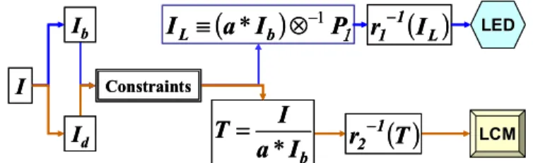
The proposed manipulation adapts the base and detail layers for determining the LED and LCM signals, respectively. The procedures are illustrated as below.
From the viewpoint of HDRD, target value (I), LED signal (IL) and LCM signal (T) of each pixel can be expressed as
I = (IL8P1)*T, (1) where 8 denotes convolution, P1 is the point spread function of single LED. From the consideration of HDRI, target value can be stated as
I = Ib + Id, (2) where Ib and Id are pixel signals of base and detail layers, respectively. All the variables in (1) and (2) are normalized. If two criteria are set as (3) and (4) below,
a*Ib = IL8P1 (3) Max.(a*Ib) = Max.(Ib + b*Id) (4) where a and b are adjustable constants and Max.() denotes the maximal value of the set of data in the parentheses. a and b here are for sufficient input light and for tuning details, respectively. The LED signal (IL) is calculated using de-convolution in (3) and LCM signal (T) by substituting (3) into (1). The flow chart of the proposed method is shown in Fig. 3.
( )
L 1 1I
r
− bI
a
I
T
*
=
r
2−1( )
T
LED LED LCM LCM(
a
I
)
P
1I
L≡
*
b⊗
−1 I Constraints Ib Id( )
L 1 1I
r
− bI
a
I
T
*
=
r
2−1( )
T
LED LED LCM LCM(
a
I
)
P
1I
L≡
*
b⊗
−1 I Constraints Ib IdFig. 3. The algorithm of theHDRI-based HDRD.
715 WFF4
16:30 – 16:45
III. EXPERIMENTAND RESULTS
The experiment is performed on a 46” HD LCD TV with backlight composed of white LEDs controlled dynamically and independently. The dynamic range of luminance of the system exceeds 10,000:1 measured by a colorimeter, CA210.
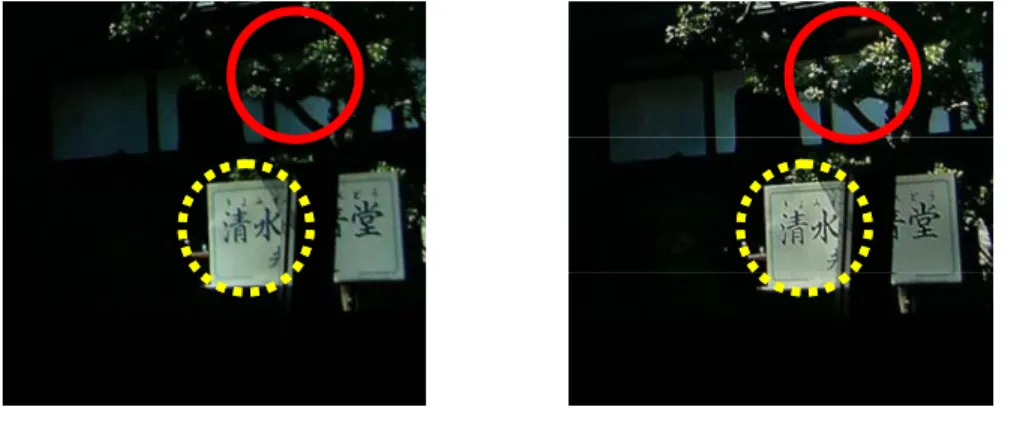
One of the results, shown in Fig. 4, demonstrates the improved details of HDRI-based HDRD. Fig. 4(a) and (b) are the photos of the result of the traditional HDRD system, and the HDRI-based HDRD, respectively. Fig. 4(b) exhibits the preserved, or even enhanced, details, while the global contrast is measured the same as the conventional HDRD for the same extreme luminance values. The characters (in yellow-dashed circle) in Fig. 4(b) are much clearer than that in Fig. 4(a). Also the sunshine spreading on the leaves (in red-solid circle) shows higher local contrast in Fig. 4(b).
IV. DISCUSSION
HDRI-based HDRD is being integrated both merits from HDRI technique and HDRD system. Some divergences, meantime, are observed from solely-applied HDRI or HDRD techniques, and are summarized as following.
A. Comparison with HDRD
Blur occurs if the LED signals are obtained prior to a desired distribution of light energy onto the input surface of LCM. Insufficient illumination onto part of LCM is also possible in the convolution of LED signals and point spread function (PSF) of the backlight. By contrast, HDRI-based HDRD can obtain more precise LED signals and provide smooth luminance variation similar to the original image.
Processing time of HDRI-based HDRD is, of course, no less than that of conventional HDRD. However, the processing time can be speeded up by several techniques and by hardware [5].
B. Comparison with HDRI
Post-processing on base layer is the main difference between pure HDRI technique and the proposed HDRI-based HDRD. After base layer being extracted from input image, pure HDRI technique, then, performs contrast reduction to fit in with a real low-dynamic-range display. The proposed HDRI-based HDRD adjusts base layer to match the dynamic range of an HDRD even that is probably of higher dynamic range. Here, the matched base layer is then used to deduce LED signals
because the matched base layer is assumed to be proportional to the light energy distribution on the backlight output.
C. Further improvement from optical design
Convolution or de-convolution in the computation process of HDRD system requires large amounts of computation. PSF, i.e. light distribution pattern of each LED in the backlight, is regarded as a mask in the calculation. Moderate PSF obtained from specific optical design on backlight is expected to speed up the process and to manipulate precisely the image details [6-7].
V. CONCLUSION
Compared to traditional solution for HDR image rendering, the HDRD is not adequate for showing the details of the pictures locally as HDRI techniques are. Based on the structure of HDRD, the algorithm has been developed. The performance of the proposed HDRI-based HDRD is demonstrated. The combination of the two techniques can maintain the global contrast and enhance local contrast at the same time. Local contrast enhancement greatly improves comfort in viewing all the details by the human visual system.
ACKNOWLEDGMENT
The authors would like to express appreciation to AU Optronics Corp. for the construction of HDRD system and measurement support.
REFERENCES
[1] H. Seetzen, L.A. Whitehead, and G. Ward, “A High Dynamic Range Display Using Low and High Resolution Modulators,” SID Symposium Digest, 1450-1453, 2003.
[2] H. Seetzen, et al., “High Dynamic Range Display Systems,” ACM Trans. on Graphics (Proc. of SIGGRAPH), 23(3): 760-768, 2004.
[3] J. DiCarlo, and B. Wandell, “Rendering High Dynamic Range Images,” Proc. SPIE, vol. 3965, 392-401, 2000.
[4] B.M. Oh, M. Chen, J. Dorsey, and F. Durand, “Image-Based Modeling and Photo Editing,” ACM SIGGRAPH, ACM Press, 433-442, 2001.
[5] F. Durand and J. Dorsey, “Fast Bilateral Filtering for the Display of High-Dynamic-Range Images,” ACM Trans. on Graphics (Proc. of SIGGRAPH), 21(3): 257-266, 2002.
[6] Y.K. Cheng, Y.W. Wang, H.P. D. Shieh, T.M. Wang, and R. H.W. Lin, “Analyses of Point spread function in high dynamic range display system,” Optics and Photonics Taiwan 2005, Serial No. G-SA-X 4-3. (Dec. 2005) [7] Y.K. Cheng, Y.W. Wang, H.P. D. Shieh, T.M. Wang, and R. H.W. Lin,
“Point Spread Function in LED-based High Dynamic Range LCD System,” to be published.
(a) (b)
Fig. 4. Results of (a) conventional HDRD system and (b) HDRI-based HDRD system