Geometry-function relationships in meta-foils
H.O. Moser
1,2*, L.K. Jian
1, H.S. Chen
3,4, S.M.P. Kalaiselvi
1, S. Virasawmy
1, X.X. Cheng
3, A. Banas
1,
K. Banas
1, S.P. Heussler
1, M. Bahou
5, B.-I. Wu
3,4, Wei Hua
1, Zhu Yi
1, 61
Singapore Synchrotron Light Source (SSLS), National University of Singapore (NUS), 5 Research
Link, Singapore 117603
2
Department of Physics, National University of Singapore, 2 Science Drive 3, Singapore 117542
3The Electromagnetics Academy at Zhejiang University, Zhejiang University, Hangzhou 310058,
China
4
Research Laboratory of Electronics, Massachusetts Institute of Technology, Cambridge,
Massachusetts 02139, USA
5
Department of Applied Chemistry and Institute of Molecular Science, National Chiao Tung
University, Hsinchu 30010, Taiwan
6
Institute of Chemical and Engineering Sciences (ICES), 1 Pesek Road, Jurong Island,
Singapore
627833
ABSTRACT
Meta-foils are all-metal free-standing electromagnetic metamaterials based on interconnected S-string architecture. They provide a versatile applications’ platform. Lacking any substrate or embedding matrix, they feature arrays of parallel upright S-strings with each string longitudinally shifted by half an S compared to its neighbour to form capacitance-inductance loops. Geometric parameters include length a, width b, thickness t, and height h of an S, the gap between adjacent S-strings d, and the periodicity p of the interconnecting lines. Equidistant strings at p=1 form a 1SE meta-foil. Grouped in pairs of gap d, exhibiting a gap dp between pairs, they are named 2SP. Geometric parameters a, b, t, h, d, dp, pS(E or P) and materials’ properties like electric conductivity, Young’s modulus, thermal expansion coefficient, and heat capacity determine the electromagnetic, mechanical, and thermal properties of meta-foils including the spectral dependence of resonance frequencies, refractive index, transmission, reflection, and bending. We show how the frequency and transmission of left-handed pass-bands depend on a, p, and dp, the pSP geometry exhibiting higher resonance frequency and transmission. Equivalent circuit considerations serve to explain physical reasons. We also demonstrate mechanical behavior versus p and dp justifying the design of a cylindrical hyperlens depending on bent meta-foils.
Keywords: Meta-foil, metamaterials, free-standing, flexible, micromanufacturing, infrared spectromicroscopy,
hyperlens
1. INTRODUCTION
Due to their vast application potential, metamaterials have aroused the interest of many researchers during the last decade1-4. One of the strategies to provide metamaterials suitable for practical applications is our development of the meta-foil5 that succeeded earlier rod-split-ring resonator work6. Much like for a conventional material, we may ask about properties of metamaterials including mechanical, thermal, electrical, magnetic, optical, chemical. In the case of the meta-foil, such properties depend solely on its geometrical parameters and properties of the structural metal.
Our motivation to develop metamaterials is related to infrared spectro/microscopy and to specific applications of cloaking. Infrared spectro/microscopy includes spectrally-resolved microscopy and spatially-resolved mapping within a certain spectral pass-band, by looking at either a small spot or small wavelength range and taking either its spectrum or spatial signal distribution, respectively. For biological systems such as cells and their sub-cellular structures and organelles, the size scale ranges from about 10 μm down to sub-100 nm. On the other hand, the spectral range in which
*moser@nus.edu.sg; phone 65 6516 7930; fax 65 6773 6734; http://ssls.nus.edu.sg Invited Paper
Metamaterials V, edited by Nigel P. Johnson, Ekmel Özbay, Richard W. Ziolkowski, Nikolay I. Zheludev, Proc. of SPIE Vol. 7711, 771119 · © 2010 SPIE · CCC code: 0277-786X/10/$18 · doi: 10.1117/12.855094
Proc. of SPIE Vol. 7711 771119-1
the biomolecules that form the structures can be distinguished from each other is the fingerprint region of the molecules, frequently attributed to 400-4000 cm-1, corresponding to 25-2.5 μm and 12-120 THz. Obviously, the spatial resolution that can be achieved with conventional microscopy, namely about λ/2, is not sufficient to see the fine details of a cell in this mid-infrared light. So, sub-wavelength resolution as promised by metamaterials is an important objective to strive for7. To overcome near-field limitations, we are working on hyperlenses for this purpose8,9. Then, other applications like filters, reflectors, absorbers, polarizers are also in reach. Exploiting the flexibility of the meta-foil, we are also pursuing cloaking devices that have been introduced into literature by their ability to conceal objects as well as the cloaking enclosure itself10-14.
In this paper, we explore both theoretically and experimentally some of the geometric parameters of meta-foils and study how electromagnetic and mechanical properties depend on them. The results will describe a parameter space within which meta-foils may be designed for specific purposes. Furthermore, such knowledge may also be used to extrapolate to spectral ranges not covered right now which is the case for the meta-foil and the fingerprint region which is the goal for our hyperlens15.
2. RESULTS
2.1. Structure and manufacturing
Meta-foils were introduced by Moser and coworkers5. They are formed by an array of parallel S-strings with a spatial phase shift of π between neighbours. The parallel S-strings are held together by transversely running interconnection lines such as to create a space-grid. Figure 1 (a) shows a few meta-foil chips after release from the substrate. They are all made of gold. It can be seen that the chips can be made with or without window-frames. They also represent different types of pSX meta-foils (Fig. 1 (b), (c)). Here, p denotes the number of S periods between subsequent interconnecting lines, S stands for S-string, and X for either E or P where E indicates equidistant and P pairwise grouped S-strings.
Fig. 1: Au pSX meta-foil. (a) Meta-foils after release from wafer. Individual chips incorporate different pSX structures, partly with window-frame, partly without. The useful meta-foil area is 8×7 mm2 (L×W). (b) 1SE meta-foil. Scale bar 20 μm. (c) 1SP meta-meta-foil. Scale bar 50 μm.
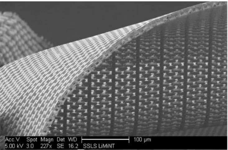
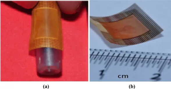
The flexibility of the meta-foil is demonstrated in Fig. 2 by the case of a 2SE meta-foil which can apparently be easily warped. A rough estimate of typical bending radii in the picture is 250 μm, smaller bending radii would be expected to be in reach if some external torque is applied. It can also be seen that the bending is easily possible in two orthogonal directions, along as well as across the S-strings, and that the internal structure of the parallel upright S-strings is well maintained, both from a cross-sectional and a top-view perspective. Bending of meta-foils is an important criterion as it is helping when optical components such as cylindrical hyperlenses or enveloping cloaks must be built.
Figure 3 shows schematics of various meta-foil geometries displaying three equidistant S-strings with interconnecting lines after each S-period, or after two or four, thus labeled 1SE, 2SE, 4SE. The standard Cartesian frame for a right- handed incident wave is indicated. The Cartesian used to describe the meta-foil has the same orientation with x pointing
Proc. of SPIE Vol. 7711 771119-2
Fig. 2: Strongly warped 2SE meta-foil. Estimated bending radii are in the 250 μm and smaller range. Scale bar 100 μm.
Fig. 3: Schematic cut-outs of meta-foils with 3 equidistant strings and periodicity 1, 2, and 4 (1SE, 2SE, 4SE). The geometric parameters used are defined in the 1SE-schematic on the left.
in k direction, y in H, and z in –E direction. THz meta-foils are micromanufactured by three-level lithography as described in 5,15.
2.2. Electromagnetic properties
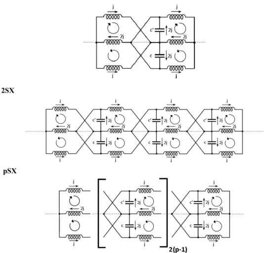
In the following, we analyse electromagnetic and mechanical properties. Electromagnetic simulations were performed by means of MWS code16, mechanical using ANSYS17. We begin electromagnetic considerations with drawing equivalent circuit diagrams of the meta-foil. Here, we consider a selected S-string coupled to its two nearest neighbours. Figure 4 shows equivalent circuit diagrams for the 1SX, 2SX, and pSX structures. Therefrom, any other pSX diagrams can be found straightforwardly by putting the internal structure 2(p-1) times between the “endpieces”. As for the capacitances, C=C’ holds in a pSE structure. If C’<C, then we have a pSP structure with capacitors C’ having reduced capacitances due to the increased gap.
The resonance frequencies of the loops are then given by
(1) for the loop with one short circuit (single-capacity loop) and
(2)
Proc. of SPIE Vol. 7711 771119-3
for the loop between two capacitors (double-capacity loop) as derived in15. Following the procedure adopted there, we find the resonance frequency for a pSE structure as
⎟⎟ ⎠ ⎞ ⎜⎜ ⎝ ⎛ − − = p LC p 1 2 2 1
ϖ
(3)correctly approaching the value for the two-capacitor-loop for large values of p.
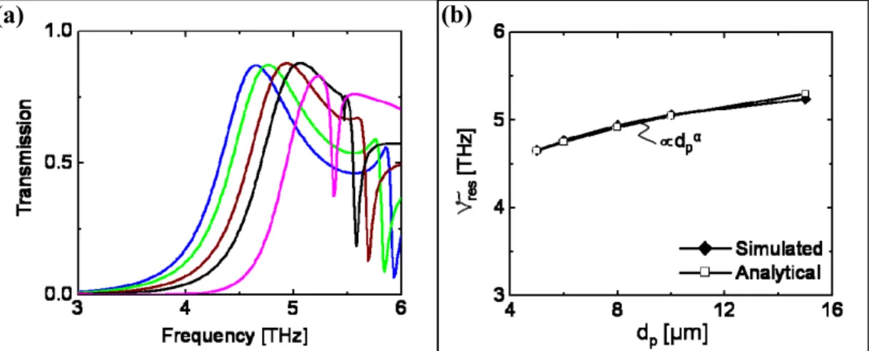
When we increase every second gap to a value dp>d, the capacitances C’ between the selected string and one neighbor are reduced, the corresponding loops will have a higher frequency, and there will be a superposition of two resonance peaks with different frequency such that the overall tendency is an increase of frequency. We see this increase of resonance frequency νres due to the diminishing capacitance between two b legs from the simulation in Fig. 5. The spectra are shifted upward with increasing dp as shown in Fig. 5 (a). Assuming that the increase of resonance frequency is described by a power law α
p
d , α is found from a least-squares fit to be α=0.12. As a plate condenser would exhibit
α=0.5, the decrease of capacity between two b legs with the gap dp is much weaker than in the case of a plate condenser as expected.
1SX
2SX
pSX
Fig. 4: Equivalent circuit diagrams based on three strings in the 1SX, 2SX, and pSX configurations where X stands for either E or P. In the E case, capacitances C and C’ are equal, in the P case not.
Proc. of SPIE Vol. 7711 771119-4
Similarly, we examine the influence of the periodicity of interconnecting lines on the resonance frequency νres for the cases of 1, 2, 3, and 4 S-strings between two adjacent interconnecting lines in an SE structure. Again, the frequency is
Fig. 5: (a) Upward shift of resonance frequency upon variation of dp from 5 to 15 μm. A gap of 5 μm corresponds to the 2SE structure whereas 10 μm represent 2SP. A gap of 15 μm has not been experimentally realized so far. (b) Comparison of the peak shift with a power law of dp. A least-squares fit of νres=c⋅dαp yields α=0.12 and c=3.83.
rising, but leveling off already from 2 to 3 and more so from 3 to 4 (Fig. 6). The reason is that going from 1 to 2, we add another circuit type to the whole problem (Fig. 4) whereas, from 2 upwards, we have only two types and just different
Fig. 6: (a) Transmission spectra versus periodicity for structures from 1SE to 4SE. Peaks are shifting monotonously upward with a big jump occurring between 1SE and 2SE followed by a rather small further increase. (b) Resonance frequency νres versus periodicity p comparing simulated and analytical results (eq. 3). numbers of them. This increases the weight of the loop between two capacitors in the averaging of the frequency over the loops as discussed above and is reasonably described by equation (3). We conclude from Fig. 6 that, in the interest of higher resonance frequency, structures with p>1 should be used.
(a)
(b)
(a)
(b)
Proc. of SPIE Vol. 7711 771119-5
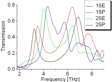
Measured spectra agree with simulated and analytical results quite well. From curves shown in Fig. 7, we deduce ratios of resonance frequencies versus dp and versus p that are in line with the simulated ones. In more detail, the ratio of the
Fig. 7: Transmission spectra of 1SE, 2SE, 1SP, 2SP meta-foils measured by Fourier transform infrared interferometry.
peak frequencies for 2SP and 2SE for which dp is 10 μm and 5 μm, respectively, is 1.074 measured from Fig. 7 and 1.087 extracted from Fig. 5 (b) agreeing within about 1%. The ratio of the peak frequencies 2SE and 1SE for which p varies from 2 to 1 is 1.27 measured whereas Fig. 6 (b) yields 1.296 simulated and 1.21 calculated within 6% agreement. We also investigate the dependency of νres on the clear width of the loops in z direction w=(a−3h)/2 (Fig. 3) keeping the width of the S-string h constant, i.e., effectively varying the free width of the U (Fig. 8). Expecting the inductance of
Fig. 8: Resonance frequency versus length of S in the 1SP case. The open width w of the U is varied from about 5.8 to 8.8 μm. This width is defined as w=(a-3h)/2 and contributes linearly to the inductance, so the resonance frequency is proportional to the reciprocal of w . (a) Simulated spectra indicating the influence of the loop size on the magnetic resonance peak, but not the electrical one. (b) Perfect agreement between simulated values and analytical formula.
(a)
(b)
Proc. of SPIE Vol. 7711 771119-6
the magnetic loops being proportional to w and, so, the frequencyνres∝1/ w , we find w to be a parameter suitable to fine tune the resonant behavior of the meta-foil. Moreover, if parameters a, b, and d were tied to h with fixed factors, the resonance frequency would become proportional to h-2+α. Thus, reducing h by one half would multiply the frequency by about four and lead into the fingerprint region, indicating substantial potential for frequency increase.
Furthermore, Fig. 8 (a) is a nice indirect proof of the magnetic resonance peak around 4 THz because this peak responds to the change of inductance via the change of w whereas the 6.8 THz peak does not. This is consistent with the 4 THz peak being a magnetic resonance and the 6.8 THz not, so an electrical one. Originally, this assignment of resonances comes out of the parameter retrieval calculations as given in5, for example.
In general, all these geometric parameters can be used together for tuning the resonance frequency. The range within reach of the present technology, i.e., maintaining direct laser writing for primary pattern generation and UV lithography for the manufacturing, extends to the long-wavelenght part of the fingerprint region. Beyond that, primary pattern generation by electron beam writing, improved mask alignment, and X-ray lithography would be required.
2.3. Mechanical properties
One of the key mechanical properties of the meta-foil is related to its bending. Bending and the minimum achievable bending radius are properties very important for building cylindrical hyperlenses and wrapped cloaks. We study the minimum bending radius as well as the minimum radius for a specific hyperlens design15 by mechanical simulation using ANSYS17. The torque is applied in two different ways, in one case pointing along the z axis of the meta-foil (along strings) and in the other case along the y-axis. Figure 9 shows meta-foil samples bent in the two respective directions.
(a) (b)
Fig. 9: Examples of bent Au meta-foils: (a) torque along z axis. Diameter of steel cylinder about 5 mm. (b) torque along y axis.
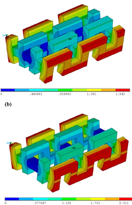
Applying torque along z means just bending the interconnecting lines leaving the chains approximately undeformed, and changing only their orientation. Furthermore, the torque required for a given bending deformation can be controlled by the periodicity of the interconnecting lines. The higher the periodicity index, the easier the bending. Obviously this is not changing the deformation of the interconnecting lines. Bending pSP meta-foils instead of pSE also can reduce the total torque, but again without changing the deformation of the interconnecting lines. Figure 10 shows ANSYS results for the case of bending around the z-axis. A torque is applied such that the deformation leads to a bending radius of 67.5 μm of the mid-plane through the interconnecting lines for the two cases of a 1SE (Fig. 10 (a)) and 1SP (Fig. 10 (b)) structure with dp=5 μm and dp=10 μm, respectively. The x-z-plane intersecting the center of the structure is assumed to be a symmetry plane. The torque is materialized by exerting tangential forces at the left and right outer surfaces. This bending is stable. Small excursions from the equilibrium position do not reduce elastic deformation energy. It can be seen that the
Proc. of SPIE Vol. 7711 771119-7
1SP structure has a slightly larger deformation at the extreme right and left because it is wider and has to account for the same curvature radius of 67.5 μm. The choice of 67.5 μm is determined by our present hyperlens design15.
(a)
(b)
Fig. 10: Total deformation in μm when a meta-foil is bent to a mid-plane curvature radius of 67.5 μm by applying a torque in z direction versus dp. (a) 1SE, dp = 5 μm, deformation scale from 0 to 1.84 μm; (b) 1SP, dp = 10 μm, deformation scale from 0 to 2.3 μm.
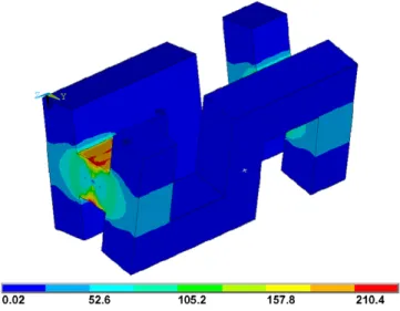
The stress distribution for the 1SE case is shown in Fig. 11 where it can be seen that the stress is maximum on the top and bottom surfaces of the interconnecting lines while the string parts have very low stress as they are just like free parts sticking out from the interconnecting lines. The maximum stress values occurring are in the 210 MPa range and, thus, much smaller than the modulus of elasticity of gold E=79 GPa 18.
Applying torque in y direction leads to more complicated deformations. The outer half of the S-string is expanded while the inner part is compressed. There is no neutral plane or symmetry plane that could be expected. This deformation is not stable, the respective “a” leg may escape to the side or even towards the centerline to reduce the elastic deformation
Proc. of SPIE Vol. 7711 771119-8
energy. The motion would only be constrained by the action of an interconnecting leg where applicable. As a consequence, it would exert a secondary torque on the b legs which would be oriented along z.
Fig. 11: The stress distribution (MPa) of a 1SE meta-foil bent around the z-axis to a curvature radius of 67.5 μm. Stress scale from 0.02 to 210.4 MPa.
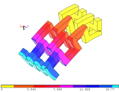
Figure 12 (a) and (b) depicts this case for the 1SE and 2SE structure, respectively. The surface pointing to the upper right corner is kept fixed and the opposite surface pointing to the lower left corner is loaded with the tangential force. It can be seen that the deformation of the Us is strongest close to the fixed end while it becomes less towards the left end. It is also obvious that the S-strings escape laterally, i.e., in y direction. The secondary deformation should become stronger when the periodicity increases which is shown in Fig. 12 (b).
(a)
Proc. of SPIE Vol. 7711 771119-9
(b)
Fig. 12: Total deformation in μm when a meta-foil is bent by a torque in y direction. The tangential force applied to the left end is 4 mN; (a) 1SE, p=1, curvature 92.5 μm and (b) 2SE, p=2, curvature 87.5 μm. Deformation scale from 0 to 16 μm.
Up to now, there has been no systematic experimental study of the bending of meta-foils. The smallest bending radius achieved so far is around 2.5 mm. However, Fig. 2 shows bending radii of a warped 2SE meta-foil that are much smaller, and which we estimate to be around 250 μm and below. From this information and the above mechanical studies, the design of a cylindrical hyperlens as presented in 15 which needs a minimum bending radius of 67.5 μm appears to be viable. Note that, in such a case of strong curvature, the incident electromagnetic wave would no longer be a plane wave. Instead, it would come from a small source volume and would be mostly radial.
3. CONCLUSION
An investigation into the structure-function relations of the meta-foil has outlined the range of electrical and mechanical parameters accessible to the meta-foil as built up-to-date. To move on, experimental results, simulation, and mechanical analysis show that presently available meta-foils manufactured by SSLS enable building a cylindrical hyperlens in the 3-4 THz range. An analysis of the electromagnetic properties indicates that it may be achievable to design and build meta-foils for resonance frequencies in the fingerprint region still using present technology involving primary pattern generation by laser writer and optical mask alignment. This would open up sub-wavelength resolution IR microscopy on biological systems and others. Beyond that, electron beam writing of the primary pattern and improved mask alignment would potentially lead to the near infrared and visible range.
ACKNOWLEDGMENTS
Work partly performed at SSLS under NUS Core Support C-380-003-003-001, A*STAR/MOE RP 3979908M and A*STAR 12 105 0038 grants. HSC, XXC, and BIW want to acknowledge the support from NNSFC (Nos. 60801005, 60531020, 60990320 and 60990322), the FANEDD (No. 200950), the ZJNSF (No. R1080320), the MEC (No. 200803351025), the ONR (No. N00014-06-1-0001), and the DAF (No. FA8721-05-C-0002).
Proc. of SPIE Vol. 7711 771119-10
REFERENCES
[1] Ramakrishna, S. A., Grzegorczyk, T. M., [Physics and Applications of Negative Refractive Index Materials], SPIE Press, CRC Press, Taylor & Francis Group, Boca Raton, USA, 2009
[2] Litchinitser, N. M., Gabitov, I. R., Maimistov, A. I., Shalaev, V. M., “Negative refractive index metamaterials in optics”, in E. Wolf, Progress in Optics 51, Elsevier B.V., 1-67(2008)
[3] Sarychev, A. K., Shalaev, V. M., [Electrodynamics of Metamaterials], World Scientific, 2007.
[4] Caloz,C., Itoh, T., [Electromagnetic metamaterials: transmission line theory and microwave applications], John Wiley & Sons, 2006
[5] Moser, H. O., Jian, L. K., Chen, H. S., Bahou, M., Kalaiselvi, S. M. P., Virasawmy, S., Maniam, S. M., Cheng, X. X., Heussler, S. P., Shahrain bin Mahmood, Wu, B.-I., “All-metal self-supported THz metamaterial – the meta-foil”, Opt. Express 17, 23914-23919(2009)
[6] Moser, H. O., Casse, B. D. F., Wilhelmi, O., Saw, B. T., “Terahertz Response of a Microfabricated Rod-Split-Ring-Resonator Electromagnetic Metamaterial”, Phys. Rev. Lett. 94, 063901(2005)
[7] Pendry, J. B., “Negative Refraction Makes a Perfect Lens”, Phys. Rev. Lett. 85, 3966 (2000)
[8] Jacob, Z., Alekseyev, L. V., Narimanov, E., “Optical Hyperlens: Far-field imaging beyond the diffraction
limit”, Opt. Express 14, 8247(2006)
[9] Liu, Z. W., Lee, H. S., Xiong, Y., Sun, C., Zhang, X., “Far-Field Optical Hyperlens Magnifying Sub-Diffraction-Limited Objects”, Science 315, 1686(2007)
[10] Pendry, J. B., Schurig, D., Smith, D. R., “Controlling electromagnetic fields”, Science 312, 1780(2006)
[11] Leonhardt, U., “Optical conformal mapping”, Science 312, 1777 (2006).
[12] Liu, R., Ji, C., Mock, J. J., Chin, J. Y., Cui, T. J., Smith, D. R., “Broadband ground-plane cloak”, Science 323,
366 (2009).
[13] Valentine, J., Li, J., Zentgraf, Th., Bartal, G., Zhang, X., “An optical cloak made of dielectrics”, Nature Mater.
8, 568 (2009).
[14] Gabrielli, L. H., Cardenas, J., Poitras, C. B., Lipson, M., “Silicon nanostructure cloak operating at optical frequencies”, Nature Photonics 3, 461 - 463(2009)
[15] Moser, H. O., Jian, L. K., Chen, H. S., Bahou, M., Kalaiselvi, S. M. P., Virasawmy, S., Cheng, X. X., Banas, A., Banas, K., Heussler, S. P., Wu, B.-I., Maniam, S. M., Hua, W., “THz meta-foil – a platform for practical applications of metamaterials”, J. Mod. Opt., 2010, submitted
[16] Microwave Studio (MWS) is a registered trademark of CST GmbH, Darmstadt, Germany. [17] ANSYS http://www.ansys.com
[18] Cohn, G., “Selected Properties of Gold”, Gold Bulletin 12, 21-24(1979)
Proc. of SPIE Vol. 7711 771119-11