IEEE TRANSACTIONS ON ANTENNAS AND PROPAGATION, VOL. 45, NO. 2, FEBRUARY 1997 305
Letters
Coplanar Waveguide-Fed Uniplanar Bow-Tie Antenna
Yu-De Lin and Syh-Nan Tsai
Abstruct- The design of coplanar waveguide (CPW)-fed bow-tie an- tenna for the 2.4-GHz ISM band is described in this letter. A coplanar waveguide-to-coplanar strips (CPW-to-CPS) balun is used to obtain the balanced feed line for the printed bow tie. Analysis method based on the mixed potential integral equation method is used to characterize the input characteristics of the bow-tie antenna. Obtained numerical results are in good agreement with experimental data. Through experiments with bow- tie antennas of various extended angles, the bow-tie antenna with a 90" extended angle exhibits the widest bandwidth in the desired frequency band which has a bandwidth of 17% for VSWR <1.5 : 1.
Index Terms- Coplanar waveguides.
I. INTRODUCTION
Due to their advantages of easy fabrication, no need for via holes, and being compatible with solid-state devices, uniplanar circuits have been under intensive investigations. Recently, the realizations of both passive and active circuits such as combiner, divider, frequency doubler, baluns, and hybrids were reported in [1]-[3]. In [4], a coplanar waveguide fed coplanar strip dipole antenna is investigated experimentally. A wideband coplanar waveguide-to-coplanar strips (CPW-to-CPS) balun is used to transform the unbalanced CPW feed line to a balanced CPS feed line for the dipole antenna. Yet, the bandwidth is limited by the dipole antenna. In this letter, a printed bow-tie antenna is proposed to improve the bandwidth. The uniplanar feature is retained by using a CPW-to-CPS balun similar to that in [4]. This antenna is designed for the mobile station antenna for the 2.4-GHz ISM band. The substrate used is the FR-4 substrate, commonly used in printed circuits and is much less expensive than the microwave substrates such as Duroid. This feature, combined with the advantages of uniplanar circuits, makes this antenna suitable as a low-cost mobile station antenna in the mobile communication system. 11. ANALYSIS AND DESIGN OF THE UNIPLANAR BOW-TIE ANTENNA
The CPW-fed printed bow-tie antenna is shown in Fig. 1. The CPW-to-CPS balun is slightly modified from that in [4]. An additional quarter-wavelength transformer is used to transform the 50-0 CPW to the 92-0 CPW. This is due to the fact that the facility for a precise 50-a CPS is not available. Two back-to-back transitions provide an insertion loss of less than 2 dB from dc to 3 GHz. The entire circuit is fabricated on an €3-4 substrate (E,. = 4.8). The substrate
thickness is 63 mils. The bandwidth of bow-tie antennas with various extended angles (6' in Fig. 1) of 0" (dipole), 30°, 60", 90", and 120" is investigated. We find that the printed bow-tie with 90" extended angle results in the widest bandwidth. For the printed bow-tie of 90" extended angle, the length of the bow-tie (WA in Fig. 1) is 965 mils for the 2.44-GHz band.
Manuscript received July 9, 1996; revised August 22, 1996. This work was supported in part by the National Science Council under Grant NSC 85-2221- The authors are with the Antenna Laboratory, Institute of Communication Publisher Item Identifier S 0018-926X(97)01456-7.
E-009-030.
Engineering, National Chiao Tung University, Hsinchu, Taiwan.
G W G
1
WA-
l
.
.
.
-
l
1
:Air
Bridgee
Fig. 1. Circuit configuration of the CPW-fed uniplanar bow-tie antenna. 0 -1 0
Q
",
-20c;:
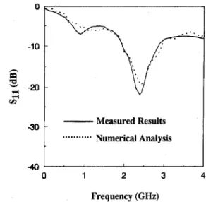
Measured Results Numerical Analysis ...a... 40 0 1 2 3 4 Frequency (GHz)Fig. 2. Measured and calculated return loss of the CPW-fed uniplanar bow-tie antenna.
To assist the design of the printed bow-tie antenna, the input characteristics of the antenna is analyzed by the mixed-potential integral equation method [5]. Triangular bases are used to model the currents on the feed lines and on the bow-tie antenna. Both numerical and experimental results of the return loss of the bow-tie antenna with a 90" extended angle are shown in Fig. 2. They are in good agreement as shown, which confirmed the validity of the analysis. The return
loss of the bow-tie antenna was measured with an HP8720 network
analyzer, with the antenna immersed in a box filled with absorbers to simulate the anechoic environment. The results show that the antenna circuit has a return loss of 23
dB
at 2.44 GHz, a bandwidth of 17% for VSWR<
1.5: 1, and a bandwidth of 36% for VSWR<
2.0: 1 . For comparison, a printed resonant half-wavelength dipole (with the extended angle 8 in Fig. 1 being 0") built on the same substrate shows a bandwidth of 13.6% for VSWR<
2.0: 1.Radiation patterns of the antenna were measured with an HP85301 antenna measurement system in an anechoic chamber. E-plane radia- tion patterns of both copolarization and crosspolarization are as shown in Fig. 3. Typical sine pattern of dipole antenna is observed and radiation in the substrate side is 2
dB
higher than radiation maximum 0018-926X/97$10.00 0 1997 IEEE~ 306 Fig. 3. tenna. Fig. 4 tenna.
IEEE TRANSACTIONS ON ANTENNAS AND PROPAGATION, VOL. 45, NO. 2, FEBRUARY 1997
0 antenna with of 90” extended angle exhibits the widest bandwidth.
With its features of uniplanar, low-cost, wide bandwidth, and dipole- like radiation patterns, the proposed uniplanar bow-tie antenna is suitable as the mobile station (handset) antenna in the personal mobile communication. -30 -180-140-100 -60 -20 20 60 100 140 180
Azimuth (degree)
Gopolarization
...Crosspolarization
E-plane radiation pattems of the CPW-fed uniplanar bow-tie an-
0 -5 h
-
3
-10 L.l P) 5 -158
3
-20 N -23E
-25 -30 REFERENCES[l] T. Tokumitsu, S . Hara, T. Takenaka, M. Aikawa, “Divider and combiner line-unified FET’s as basic circuit function modules-Part I and Part 11,”
IEEE Trans. Microwave Theory Tech., vol. 38, pp. 1210-1226, Sept. 1990.
[2] T. Takenaka and H. Ogawa, “An ultra-wideband MMIC balanced frequency doubler using line-unified HEMT’ s,” IEEE Trans. Microwave
Theory Tech., vol. 40: pp. 1935-1940, Oct. 1992.
[3] C.-H. Ho, L. Fan, and K. Chang, “New uniplanar coplanar waveguide hybrid-ring couplers and magic-T’s,” IEEE Trans. Microwave Theory Tech., vol. 42, pp. 2440-2448, Dec. 1994.
[4] K. Tilly, X.-D. Wu, and K. Chang, “Coplanar waveguide fed coplanar strip dipole antenna,” Electron. Lett., vol. 30, no. 3, pp. 176-177, 1994.
[5] J. R. Mosig, “Arbitrary shape microstrip structures and their analysis with a mixed potential integral equation,” IEEE Trans. Microwave Theory Tech., vol. 36,, pp. 314-323, Feb. 1988.
Slot-Coupled DR Antenna
for Dual-Frequency Operation
Z. Fan and Y. M. M. Antar
Abstract-To achieve dual-band operation or wider bandwidth, a new configuration of dielectric resonator antenna is proposed. This structure consists of two rectangular dielectric resonators displaced near two edges of a single slot in the ground plane of a microstrip line. The measured impedance and radiation patterns for two cases are presented. The results for typical examples indicate that impedance bandwidth twice that of a single element or dual-frequency operation at two separate bands can be achieved.
I
Index Terms-Dielectric resonator antennas.- 4 0 ‘ I ’ ‘ I I ’ I ’
‘
-180-140-100 -60 -20 20 60 100 140 180 I. INTRODUCTION
Azimuth (degree)
Copolarization
In recent years, there has been continuing interest in investigations of dielectric resonator (DR) antennas due to their advantages, such as high radiation efficiency, ease of fabrication, and ability of coupling to commonly used feeding schemes. The basic dielectric resonator antenna (DFU) structure is composed of a DR element of a specific shape (hemispherical, cylindrical, rectangular, or triangular) excited by a single feed such as a microstrip line, coplanar waveguide, aperture, or coaxial cable [l], [2]. For this simple configuration wider ...
Crosspolarization
H-plane radiation patterns of the CPW-fed UniPlanar bow-tie an-
in the air side. H-plane radiation patterns of both copolarization and crosspolarization are shown in Fig. 4. Typical omnidirectional pattern of the dipole antenna is observed. Gain variation is much smaller than that obtained in [4].
111. CONCLUSIONS
Analysis and design of a uniplanar bow-tie antenna on an inexpen- sive PC substrate for the 2.4-GHz ISM band is described in this letter. Numerical results based on the mixed potential integral equation method were validated by measurement. By comparing the properties of bow-tie antennas with various extended angles, we found that the
bandwidth can be achieved by decreasing the permittivity of the DR and by optimizing the geometrical ratios of the DR. However, using dielectric material with a smaller value of permittivity results in larger structural dimensions of the DR. To widen the bandwidth, the use of stacked or parasitic coplanar structures have been suggested and studied experimentally for cylindrical DR antennas [3], [4]. The purpose of t h s paper is to propose a novel DRA structure consisting of two DR elements located near two edges of a single slot in the
Manuscript received March 1, 1996; revised October 14, 1996.
The authors are with the Department of Electrical and Computer Engineer- Publisher Item Identifier S 0018-926X(97)01457-9.
ing, Royal Military College of Canada, JSingston, ON, K7K 5L0, Canada