A Robust Channel Estimator for High-Mobility
STBC-OFDM Systems
Hsiao-Yun Chen, Associate Member, IEEE, Meng-Lin Ku, Shyh-Jye Jou, Senior Member, IEEE, and
Chia-Chi Huang
Abstract—In this paper, a robust channel estimator for
high-mobility space-time block code-orthogonal frequency division multiplexing (STBC-OFDM) systems is proposed and applied in IEEE 802.16e systems. A high-performance two-stage channel estimation method is adopted. The proposed architecture reduces computational complexity effectively and improves 85.2% of the hardware implementation. The performances of the proposed design have been demonstrated through the simulation of an STBC-OFDM system with two transmit antennas and one receive antenna. At the vehicle speed of 120 and 240 km/hr for quadrature phase shift keying (QPSK) modulation, the proposed design can achieve the bit-error rate (BER) of about10 4and10 3without using channel coding. Moreover, it has significant performance improvement as compared with interpolation-based channel esti-mation methods. The proposed channel estimator implemented in 90 nm CMOS technology can support up to 29.03 Mbps (uncoded) downlink data transmission. The design only requires 859.6 K gates and dissipates 43.71 mW at 83.3 MHz operating frequency with 1 V power supply.
Index Terms—Channel estimator, space-time block code,
orthog-onal frequency division multiplexing, IEEE 802.16e.
I. INTRODUCTION
I
N recent years, space-time block code (STBC)-orthog-onal frequency division multiplexing (OFDM) techniques (STBC-OFDM) have been shown to be very promising [1]–[3]. With multiple transmit antennas, STBC can provide transmit diversity gain to improve system performance in wireless communications, especially when receive diversity is too ex-pensive to deploy. STBC-OFDM systems have been adopted in IEEE 802.16e which is an extension of IEEE 802.16-2004 for supporting the mobility of wireless metropolitan area network (WMAN) [4], [5]. However, for STBC decoding, STBC-OFDM systems require accurate channel state informa-tion (CSI), which is particularly difficult to obtain in mobile wireless channels. Therefore, high quality channel estimation with acceptable hardware complexity is a crucial challenge for realizing a successful STBC-OFDM system.Manuscript received November 26, 2008; revised April 07, 2009. First published December 22, 2009; current version published April 09, 2010. This work was supported by the UMC, MediaTek Inc., CIC and the National Science Council of Taiwan, under Grant NSC96-2220-E-9-4. This paper was recommended by Associate Editor C.-Y. Chi
H. Y. Chen and S. J. Jou are with Department of Electronics Engineering, National Chiao Tung University, Hsinchu 300, Taiwan (e-mail: jerryjou@mail. nctu.edu.tw).
M. L. Ku and C. C. Huang are with Department of Communications Engi-neering, National Chiao Tung University, Hsinchu 300, Taiwan.
Digital Object Identifier 10.1109/TCSI.2009.2027629
Various channel estimation methods have been proposed for OFDM systems. Among these methods, discrete Fourier transform (DFT)-based channel estimation methods using either minimum mean square error (MMSE) criterion or max-imum likelihood (ML) criterion have been studied for OFDM systems with preamble symbols [6]–[8]. Since no information on channel statistics or operating signal-to-noise ratio (SNR) is required in the ML scheme, the ML scheme is simpler to imple-ment than the MMSE scheme [6]–[8]. Furthermore, when the number of pilots is sufficient, the two schemes have comparable performances [8]. For this reason, the decision-feedback (DF) DFT-based channel estimation method is adopted to use the decided data as pilots to track channel variations for providing sufficient tracking information. Recently, Ku and Huang [9], [10] presented a DF DFT-based method derived from ML criterion and Newton’s method. Moreover, they concluded that a refined two-stage channel estimation method [10] is more robust than the classical DF DFT-based method to apply in fast time-varying channels. Thus, the two-stage channel estimation method with an initialization stage and a tracking stage is adopted in this paper. Nevertheless, the two-stage channel estimation method has high computational complexity and is difficult to realize in hardware directly; hence, a novel architecture and an implementation method shall be proposed to reduce the hardware complexity.
In this paper, a robust channel estimator for high-mobility STBC-OFDM systems is proposed and implemented in IEEE 802.16e baseband receiver. The channel estimator designed in 90 nm CMOS technology can support up to 29.03 Mbps (uncoded) downlink data transmission. This design has about 859.6 K gates and dissipates 43.71 mW at 83.3 MHz operating frequency. As compared with interpolation-based channel esti-mation methods which are commonly adopted in the channel estimator designs [11], [12], our proposed channel estimator has significant performance improvements, especially when it is applied in fast and selective fading channels. The proposed channel estimator includes the following features:
• implementation of a robust channel estimator applied in an STBC-OFDM system with two transmit antennas and one receive antenna;
• adoption of a high-performance two-stage channel estima-tion method for providing precise CSI in high-mobility wireless channels;
• provision of an efficient channel estimator architecture for low-complexity hardware implementation while keeping the high performance.
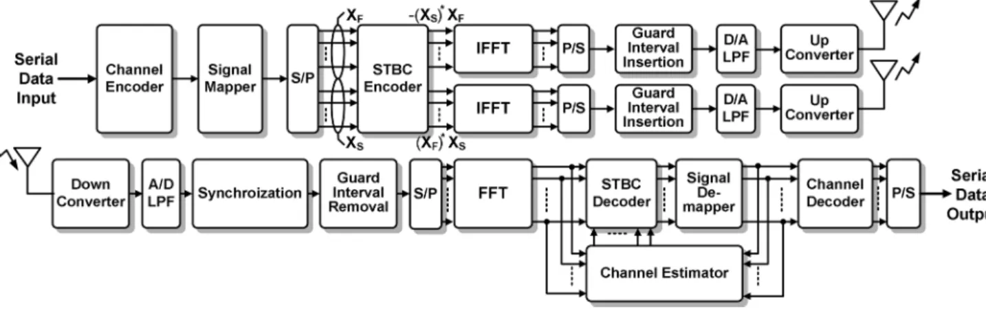
Fig. 1. Proposed STBC-OFDM system with two transmit antennas and one receive antenna.
TABLE I
MAJORPARAMETERS OF THEPROPOSEDSTBC-OFDM SYSTEM
This paper is organized as follows. Section II describes the system architecture. Section III briefly reviews the two-stage channel estimation method. Section IV presents the proposed channel estimator. Then, the simulations and results are pro-vided in Section V. Finally, Section VI is the conclusions.
Notation: By convention, boldface letters are used for sets, vectors, and matrices. The superscript stands for complex conjugate. The notation takes the sign of . The nota-tions and stand for the real part and the imaginary part of . The notation denotes the contain elements of a set or a vector.
II. SYSTEMARCHITECTURE
The orthogonal frequency division multiple access (OFDMA) specification of IEEE 802.16e that supports the multi-antenna technology is adopted in this paper. In downlink (DL) transmission, the subcarrier allocation of partial usage of subchannels (PUSC) is supported in this proposed system. The major parameters of the proposed STBC-OFDM system are summarized in Table I. The quadrature phase shift keying (QPSK) and 16 quadrature amplitude modulation (16QAM) are supported for data subcarriers, while binary phase shift keying (BPSK) is adopted for pilot subcarriers and preamble symbols. Each frame is composed of one preamble symbol and 40 OFDM data symbols. The cyclic prefix (CP) length is 128 sampling periods, i.e., 1/8 of the useful symbol time.
The proposed STBC-OFDM system with two transmit an-tennas and one receive antenna is shown in Fig. 1. In the trans-mitter, Alamouti’s STBC encoding method [1] is used to encode two transmitted symbols,
and , within a time slot
which is the duration of two OFDM symbols, where is the subcarrier index, and is the total number of subcarriers. The -point inverse fast Fourier transform (IFFT) unit is used in each arm to transform the frequency domain OFDM symbols into time domain. The CP with time duration is then inserted as a guard interval to combat inter-symbol interference (ISI). Fi-nally, a complete OFDM symbol with symbol duration
is converted into an analog signal by a digital-to-analog (D/A) converter, filtered by a low-pass filter (LPF), up converted to RF band, and transmitted in air.
The receiver architecture consists mainly of a channel esti-mator along with other blocks. After an RF signal has been re-ceived from an antenna, it is down converted to the equivalent baseband, low-pass filtered, and digitized by an analog-to-dig-ital (A/D) converter. Both timing and carrier frequency synchro-nization are assumed to be ideal in this case. The channel is assumed to be quasi-static within any two successive OFDM symbol durations. Hence, without loss of generality, the signal processing of the received data is focused on each time slot, and the symbol time index is omitted hereafter except other-wise stated. The channel frequency response between the first transmit antenna and the receive antenna is denoted as , and the other one is denoted as . Within a time slot, after the received signals have passed through the guard interval re-moval and the -point fast Fourier transform (FFT), the two successive received OFDM symbols, and , are given by
(1) (2) for , where and denote the sets of data and pilot subcarrier indices, respectively, and and are the uncorrelated additive white Gaussian noise (AWGN) with zero-mean and variance .
III. TWO-STAGECHANNELESTIMATIONMETHOD
Most mobile wireless channels are characterized by channel impulse response (CIR) consisting of a few dominant paths. These path delays usually change slowly in time, but the path gains may vary relatively fast. In this section, the refined two-stage channel estimation method [10] will be briefly reviewed. An initialization stage uses a multipath interference cancellation (MPIC)-based decorrelation method to identify the significant paths of CIR in the beginning of each frame. However, the CIR estimated by the preamble can not be directly applied in the fol-lowing data bursts since the receiver is mobile. Thus, a tracking stage is then used to track the path gains with known CIR posi-tions. The details are described as follows.
A. Initialization Stage
The MPIC-based decorrelation estimates CIR path-by-path and cancels out the known multipath interference. The channel estimation for each transceiver antenna pair can be indepen-dently performed because the preambles transmitted from different antennas do not interfere with each other. First, two parameters and are defined as a presumptive path number of a channel and an observation window set, respec-tively. Second, the cyclic cross-correlation between the received and transmitted preambles as well as the normalized cyclic auto-correlation of the transmitted preamble are calculated. The indexes and which stand for a path counting variable and the number of the legal paths found by the MPIC-based decorrelation are initialized to zero. Third, the process is started by picking only one path whose time delay yields the largest value in , for . If the path delay is larger than the length of CP, this path is treated as an illegal path and discarded by setting . Otherwise, this path is recorded as the -th legal path with a time delay and a complex path gain . Then, the interference associated with this legal path is canceled from
to obtain a refined cross-correlation function
(3) Meanwhile, is increased by one. The value of is also in-creased by one at the end of each iteration, and the iterative process is continued until reaches the presumed value of . B. Tracking Stage
After the initialization stage, we can obtain the information of the path numbers , the multipath delays , the
mul-tipath complex gains , for , and the
corresponding channel frequency responses, where is corre-sponding to the -th transmit antenna. Under the assumption that the multipath delays do not change over the duration of a frame, the DF DFT-based channel estimation method can be equiva-lently expressed in Newton’s method as [9]
(4) (5)
(6)
According to [9], the vector
cal-culates the difference between the previous estimated channel frequency response vector
and the least-square (LS) estimation vector in (4), where is the iteration index. The matrix is the re-encoded STBC matrix with decided symbols, and , as its entries. The decided symbols are obtained by applying the previous estimated channel frequency responses to decode the received
signal vector , where is the symbol
index within a time slot. The value
is the energy normalization factor. The inverse DFT (IDFT) ma-trix multiplying by the vector
in (5) is to form the gradient vector in Newton’s method as shown in (6), where is a subset of . In addition, the weighting matrix in (6) is in fact the inverse of the Hes-sian matrix in Newton’s method [9]. The -th entry of is given by
(7)
In the previous studies [6], [7], the pilots as well as the decided data symbols are simultaneously adopted to perform channel estimation at each tracking iteration. From the view-point of optimization, since the pilots inserted in each OFDM symbol are much more reliable than the decided data symbols, they should play a dominant role in providing a global search direction at the first tracking iteration [10]. Thus, the first iteration of the channel tracking is modified as
(8) where the gradient vector is calculated according to (4)–(5) by using the pilot subcarrier set instead of the set , and the value is an experimental constant of step size to have the best performance.
It is demonstrated in [10] that the two-stage channel esti-mation method has better performance than the classical DF DFT-based method, the STBC-based MMSE method, and the Kalman filtering method for estimating channels in high mobility, and its computational complexity is quite the same with these methods. However, the high complexity problem still needs to be solved for hardware implementation. Hence, we propose a modified two-stage channel estimation method and its architecture for hardware design.
IV. PROPOSEDCHANNELESTIMATOR
The overall block diagram of the proposed channel estimator is shown in Fig. 2. The initialization stage is decomposed to a preamble match, an IFFT, a straight MPIC (SMPIC)-based decorrelator, and an FFT. The tracking stage is decomposed to an STBC decoder, a demapper, an LS estimator, an IFFT, a path
Fig. 2. Overall block diagram of the proposed channel estimator.
decorrelator, a Hessian matrix calculator and an FFT. Moreover, the IFFT and FFT are shared between the initialization stage and the tracking stage. These key blocks are described in the following subsections.
A. Initialization Stage: Preamble Match
In the initialization stage, the preamble match is used to esti-mate the preliminary channel frequency responses for by matching the received signal with the preamble transmitted from the -th antenna. Since the preambles transmitted from different antennas do not interfere with each other, can be independently performed by
(9) where in the initialization stage is the first received OFDM symbol of a frame, and is AWGN. The values of pre-amble subcarriers are known patterns; besides, the subcarriers are modulated by BPSK and boosted as a constant power to increase the reliability. Thus, the absolute values of preamble subcarriers normalized by the power can be pre-computed to a real constant . Furthermore, the value can be quantized to a canonic sign digit (CSD) code [13] with two nonzero digits for the purpose of using only shifters and adders in-stead of multiplier implementation to reduce the design com-plexity. The can be reformulated as
(10) The preamble match design consists of subtractors and mul-tiplexers controlled by the sign of for forming the oper-ations of (10) as shown in Fig. 3.
B. Initialization Stage: SMPIC-Based Decorrelator
After IFFT operation, the CSIs are obtained in time domain . The MPIC-based decorrelation method estimates CIR path-by-path. It picks the maximum path of for
and cancels the maximum path interference to other paths. If the set has paths, the process must iterate times for
Fig. 3. Basic design unit of the preamble match.
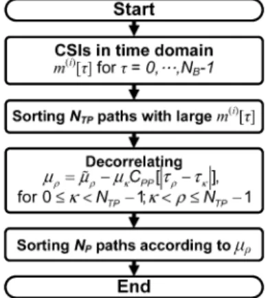
Fig. 4. Flowchart of the proposed SMPIC-based decorrelation.
finding the maximum path of these paths and canceling the maximum path interference to other ( -1) paths. This method requires too many execution cycles and is unsuitable to directly implement in the proposed channel estimator.
In order to reduce the execution cycles, we propose an SMPIC-based decorrelation method to identify significant paths in a straightforward method, and the flowchart is shown in Fig. 4. First, the proposed scheme sorts the paths to find the first paths with large . Second, the decor-relation is carried out from the largest to the smallest one of these paths to cancel the path interference. Finally, the decorrelated paths are sorted again to pick up the first
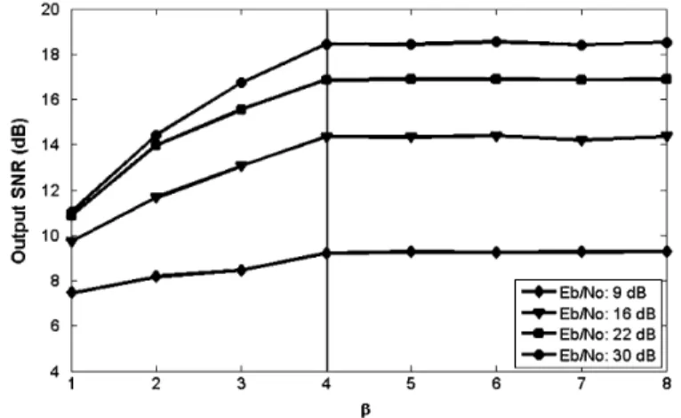
paths. For using a sorting network of fixed I/O size to sort an arbitrarily larger data set, the number of is defined to be , and is an integer which is searched to optimize the computational complexity and guarantee the acceptable performance. Here, the output SNR at the STBC decoder is used as a gauge of the system performance to determine the value of and defined as
(11) (12)
(13)
(14)
where is the number of symbols in a constellation, is the number of data belonging to the -th symbol after being sliced, and is the desired data after STBC decoding.
If a sorting algorithm such as merge sorting is used, the com-putational complexity of the original MPIC-based decorrelation
method requires comparisons,
complex multiplications and complex subtractions because it must repeat times of sorting and decorrelation of paths. However, the complexity of the SMPIC-based decorrelation method only requires compar-isons, complex multiplications and complex subtractions. Thus, the requirement of execution cycles can be effectively reduced by about times.
For this channel estimator, is defined to be 128 which is the CP length, and is presumed to be eight. Fig. 5 shows the curves of the output SNR in QPSK modulation versus the value of . These curves are simulated at the vehicle speed of 120 km/hr with different which is defined as a ratio of received bit energy to the power spectral density of noise. The value of is decided to be four where the curves of the output SNR get into saturation. Hence, the value of is 32. As compared with the original method, the performance loss due to the quantization of is smaller than 0.5 dB when the bit error rate (BER) is at 10 .
The architecture of the SMPIC-based decorrelator requires a very efficient partial sorting network and a decorrelator. We propose a merge sorting network with programmable and partial sorting capability and a triangular decorrelator (TD). 1) : In order to avoid the high complexity of parallel sorting network, a fixed I/O size sorting network and a set of memory module are used to accommodate the number of sorting elements [14]–[16]. Here, the architecture of the MSNP with a memory bank, a sorting control unit and an 8-item sorter is shown in Fig. 6. The 8-item sorter is the Batcher’s sorting net-work with I/O size of eight. The Batcher’s sorting netnet-work is widely used because of its inherent parallelism and short latency [17]. Fig. 7 shows the 8-item sorter, and the basic unit is a 2 2 comparator which is used to perform data comparison and ex-change. The memory bank which is primarily used to save the
Fig. 5. Output SNR versus the value of .
Fig. 6. Block diagram of theMSNP .
Fig. 7. Batcher classic sorting network with I/O size of eight.
path power values is organized into eight independent memory modules denoted as – .
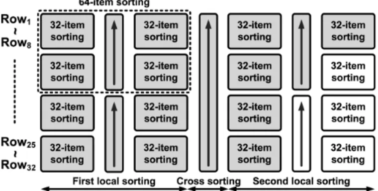
Since the maximum sorting item is 128, the sorting data (path power values) are arranged with 32 rows which the row defini-tion is used in the sorting sequence, and each row contains four sorting data. The odd rows are loaded into – , and the even rows are loaded into – . Based on the sorting se-quence, the sorting control unit takes two rows of data to the 8-item sorter for sorting in each cycle; then, the outputs of the sorter which are divided into two clusters in descending order are written back to the memory bank and replaced the original two rows. The -item merge-sorting sequence can be divided into three cycles: 1) the first local sorting cycle; 2) the cross sorting cycle; and 3) the second local sorting cycle. At the first local sorting cycle, -item data are divided into two -item data clusters to do -item merge-sorting, respectively. Then,
Fig. 8. 32-item merge sorting sequence.
Fig. 9. 128-item merge sorting sequence.
-item data will be arranged in two -item clusters in de-scending order. At the cross sorting cycle, the data in the up cluster are compared and exchanged with the data in the down cluster. After cross sorting, the data in the up cluster are larger than that in the down cluster. At the second local sorting, the two clusters are sorted separately again in descending order. Fi-nally, the sorted results are saved in the memory bank and ar-ranged in the row order. Fig. 8 shows the 32-item merge sorting sequence represented by the directed arrows in the line repre-sentation, and each arrow represents an operation of the 8-item sorter. The merge sorting is used two times in the SMPIC-based decorrelator. The first time is to sort the 128-item data to find the first 32-item data and denoted as 128-32-item sorting. The second time is to sort the 32-item data to find the first 8-item data and denoted as 32-8-item sorting. The 32-item sorting sequence is used to be a basic control sequence, and the 128-item sorting sequence can be extended by the 32-item sorting sequence and constructed as the line representation shown in Fig. 9. For saving execution time and power, the 128-32-item sorting only exe-cutes the grey part of Fig. 9, and the 32-8-item sorting exeexe-cutes the grey part of Fig. 8.
2) TD: The TD consists of a decorrelated control unit, a decorrelated unit, and a memory bank shared with the sorting process. The TD is executed after the first 128-32-item sorting. There are 31 iterations of the TD process, and the process starts at the first legal path which is the maximum sorted path. If denotes the iteration number, for , the process of the
-th iteration is to cancel the interferences associated with the -th legal path gain. The process can be expressed as
(15)
Fig. 10. Design of the decorrelated unit.
where is the -th legal path gain, is the -th sorted path gain, is the -th decorrelated sorted path gain, is the -th legal path delay, is the -th sorted path delay, and is the normalized cyclic auto-correlation of the preamble. The process of the -th iteration executes times of decor-relating calculation. At the -th iteration, the process does not decorrelate the interference to the first legal paths since the interference value is much smaller than their path gains and does not influence the accuracy of the decision in the significant path positions. Moreover, the small path gain offset can be re-vised in the tracking process without loss of the performance. In this way, the TD process can effectively save about half of execution cycles and power consumption. After the -th itera-tion processing, the -th legal path is acquired to execute the next iteration. Because the preamble is a known pattern, the value of with different can be calculated and stored in ROM in advance. After 31 iterations have been completed, the 32 legal paths are obtained and then sorted again to find eight significant paths. Therefore, following the process of the 32-item decorrelation, the decorrelated control unit is designed to control the access flow of the sorted paths and the decorre-lated paths. Fig. 10 shows the design of the decorredecorre-lated unit. Within the execution of the -th iteration, must be used (31-) times; hence, is read from memory at the beginning and saved in the local registers to reduce memory access until the iteration is finished.
After the SMPIC-based decorrelator, the significant paths have been identified and are then transformed to channel frequency responses by FFT for using as the reference in the tracking stage.
C. Tracking Stage: STBC Decoder and Demapper
In the tracking stage, from (4), the LS estimator is used to calculate the LS estimations followed by calculating the vector
that can be expressed as
(16)
(17) Before the LS estimation calculation, the decided symbols and must be determined first. Based on the latest estimated channel frequency responses, the STBC decoder and
Fig. 11. Design of the LS estimator.
the symbol demapper are used to decode these two received symbols and can be formulated as
(18)
(19) where is the demapper process. The hardware design of a divider is very costly; therefore, a demapping dichotomy method with two stages [18] is adopted to avoid the divider im-plementation. Also, a complex multiplier can be reduced from four multipliers and two adders to three multipliers and five adders. Hence, the design of the STBC decoder only requires 12 multipliers and 24 adders.
D. Tracking Stage: LS Estimator
After the decided symbols have been determined, the LS es-timations, for , are calculated by the LS
esti-mator. Both and denote the and
coordi-nate values of and , respectively. Both
and denote the real part and the imaginary part of and , respectively. The value of constellation nor-malization and the value of both have a limited constant set; thus, these multiplications can be merged to one multiplica-tion of , and the value of has also a limited constant set. The LS estimations can be expressed as
(20)
(21)
Fig. 12. Design of the coordinate precalculator.
Fig. 11 shows the design of the LS estimator which is com-posed of coordinate precalculators, LS units, an LS control unit and a final normalization. The coordinate precalculators are de-signed to generate the partial products of multiplied by the coordinate values. The coordinate precalculators support the modulations of BPSK, QPSK, and 16QAM, and the multiples should be . Fig. 12 shows a coordinate precalculator implemented by carry propagate adder (CPA). An LS unit in-cluding multiplexers and adders is used to generate the LS es-timation results without normalization. The LS control unit is based on the values of , and to generate the con-trol signals for selecting the outputs of the coordinate precal-culators, controlling the adders to add or subtract and choosing the results multiplied by the corresponding value of . Since the value of has a limited constant set, all possible values can be applied by CSD coding and then searched their common subex-pressions to implement CSD multiplications to avoid the usage of dividers. Finally, the result is outputted after the final normal-ization.
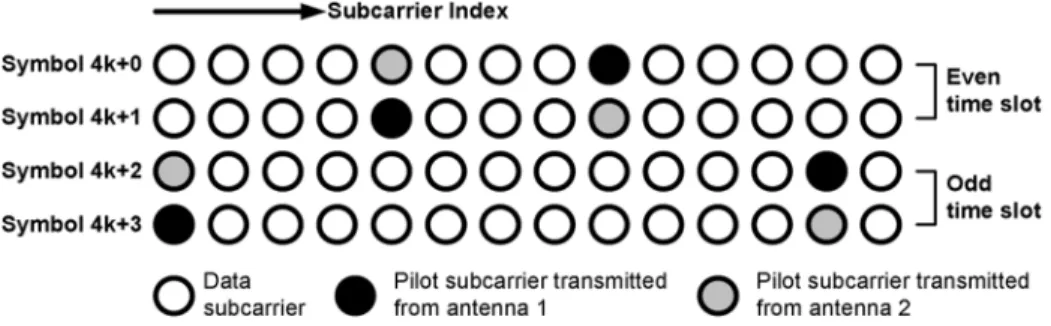
Fig. 13 shows the pilots which are transmitted in the cluster structures over different time slot. In IEEE 802.16e, each cluster contains 14 subcarriers, and there are 60 clusters in an OFDM symbol with 1024 subcarriers. Each cluster has two pilot subcar-riers, and the pilots are modulated by BPSK. If a pilot is trans-mitted on one pilot subcarrier from one antenna, the other an-tenna will not transmit a pilot on the same subcarrier to avoid the inter-antenna interference. The dimension of is . Ac-cording to this allocation, if the pilot subcarrier index is
, the LS estimations at the first itera-tion can be expressed as follows:
Fig. 13. Pilots transmitted in the cluster structures over different time slots.
(23) where the index is in the range , and is a constant value to represent the absolute pilot value normalized by the pilot power. Therefore, the LS estimations at the first iteration can be implemented by a constant CSD multiplication. After the LS estimation calculation, is acquired by sub-tracting the LS estimations from the latest estimated channel frequency responses.
E. Tracking Stage: Hessian Matrix Calculator and Path Decorrelator
We then pass through IFFT to obtain in time domain. Only those gradient entries of that have the same path delays as the significant paths identified in the initialization stage are considered; therefore, white noise will be filtered out, and the decision error propagation effect can also be allevi-ated. Since data and pilot subcarriers are not equally-spaced, the aliasing between the paths occurs. The path decorrelator works to decorrelate the inter-path interferences. Before the path decorrelation, the inverse of the Hessian matrix, , should be calculated first. Although is only calculated once within a frame operation, the matrix inverse computation needs very high complexity of ) complex multiplications. Besides, each entry of should take at least cycles to calculate the cosine and sine summations by using a look-up table, where is the dimension of . If is imple-mented directly, it will require very large hardware module and memory. In order to reduce the requirement, the matrix inverse is avoided by considering the strongly diagonal property [10]. If is the significant path number, is decomposed to
, where is a identity matrix,
and is a zero-diagonal matrix. If is large enough, an approximate weighting matrix of takes the form as
(24) Furthermore, the -th entry value can be represented as
(25)
If is used to denote , when , the value of , denoted as , can be further expressed to
(26)
Because the significant path delays are smaller than ,
the value of is in the range . For low
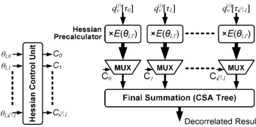
complexity implementation, all possible values of can be calculated first. Since the inter-path interference degrades sharply when gradually becomes large, many values of after the numerical quantization are very small and near to zero. Hence, those nonzero quantized values can be expressed in CSD codes and searched for their common subexpressions; then, the multiplications of can be implemented by CSD multiplications. We merge the Hessian matrix calculator into the path decorrelator, and there are four components to compose this path decorrelator: Hessian precalculators, a Hessian control unit, selectors, and a final summation. Fig. 14 shows the block diagram of this path decor-relator implemented in parallel form. The Hessian precalculator employs CSD multiplications to multiply the un-decorrelated with the possible values of , and it is only executed once during the operation of the path decorrelator. Then, based on the value of , the Hessian control unit generates the control signals for selecting the corresponding results gener-ated by the Hessian precalculators. Finally, the corresponding results are selected by the selectors and summarized by the final summation to form one path decorrelation. The design just needs cycles to complete all path decorrelations in parallel form; otherwise, it needs * cycles in serial form.
As described above, the path decorrelator efficiently avoids computing the Hessian matrix and the matrix inverse. It uses only adders and multiplexers instead of many complex multi-pliers and a lot of memory; besides, the redundant computations are also removed by sharing the results of the Hessian precalcu-lators. Therefore, the path decorrelator highly reduces the hard-ware complexity and leads to low-power application simultane-ously.
Fig. 14. Block diagram of the path decorrelator.
Fig. 15. Radix-8 1024-point parallel memory-based FFT architecture.
After the path decorrelator, the decorrelated gradients pass through FFT to acquire the gradients in frequency domain. Fi-nally, the new estimated channel frequency responses are up-dated by subtracting these gradients from the latest estimated channel frequency responses.
F. FFT/IFFT Module
The FFT and IFFT are shared between the initialization stage and the tracking stage. Since the tracking stage tracks channel variations in an iterative way, the latency of FFT and IFFT is a main issue to achieve the design requirement. Therefore, a parallel memory-based FFT/IFFT architecture which provides multiple inputs and outputs in normal order is adopted to reduce the latency requirement (less than 1/4 of one OFDM symbol time) and to work in low clock rate. Fig. 15 illustrates the archi-tecture of radix-8 1024-point parallel memory-based FFT with eight independent memory modules. This architecture consists of eight single port memory modules, four radix-8 processing elements (PE), two radix-2 butterfly elements, and commuta-tors between memory modules and PEs. Two classes of PE ar-chitecture are popular in the literature: single-path delay feed-back (SDF) and multi-path delay commutator (MDC) [19], [20]. Considering cost, complexity and throughput, the radix-8 PE employs an 8-point pipelined SDF FFT architecture, as shown in Fig. 16.
Only partial outputs of IFFT and partial inputs of FFT are used in the two-stage channel estimation method. Therefore, in the future, the FFT/IFFT module can be further studied with the
Fig. 16. Radix-8 processing element.
TABLE II
WORDLENGTHS OFSEVERALKEYSIGNALS IN THECHANNELESTIMATOR
partial FFT algorithm [21] to reduce the computational com-plexity and memory-access operations, and it can also be im-proved by the scaling algorithm [22] with shorter word length. G. Word Length Optimization
The optimization of finite word length not only reduces hardware complexity but also guarantees acceptable system performance. The output SNR at the STBC decoder, as defined in (11)–(14), is used as a performance criterion to determine the appropriate word length of each building block. The word lengths of several key signals in the channel estimator are summarized in Table II.
V. SIMULATIONS ANDDESIGNRESULTS
The performances of the proposed channel estimator are demonstrated through the simulation of an STBC-OFDM system with two transmit antennas and one receive antenna. The multipath channels adopt the International Telecommuni-cation Union (ITU) Veh-A [23] channel model with relative
path power profiles of 0, , and (dB),
and the path excess delays are uniformly distributed from 0 to 50 sampling periods. Moreover, the Jakes model is used to generate a Rayleigh fading environment [24].
Fig. 17. BER performances atv of 120 km/hr.
Fig. 17 shows the BER performances of the proposed scheme and the hardware version with four tracking iterations at the ve-hicle speed of 120 km/hr which is equivalent to the Doppler frequency of 277.8 Hz. The hardware version is simulated with fixed word length. The result of perfect channel estima-tion, denoted as perfect CSI, is included for benchmarking. The performance curves of the proposed scheme and the hardware version are very close to the perfect CSI curve. In QPSK mod-ulation, the curve of the hardware version has about 0.2 dB gap in as compared with the proposed scheme and about 0.8 dB gap in as compared with the perfect CSI case at . In 16QAM modulation, the curve of the hard-ware version has about 0.5 dB gap in as compared with the proposed scheme and about 1.2 dB gap in as com-pared with the perfect CSI case at .
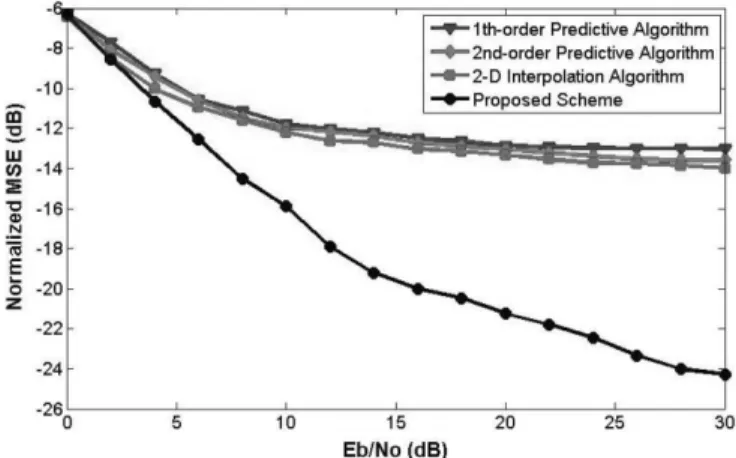
Three kinds of interpolation-based channel estimation methods, the 1st-order predictive algorithm, the 2nd-order pre-dictive algorithm and the two dimensional (2-D) interpolation algorithm [11], [12], are simulated to make the performance comparison. Considering the IEEE 802.16e OFDMA downlink specification, these methods are executed based on the cluster structures (Fig. 13) where a cluster consists of 14 consecutive subcarriers with alternating structures in two successive time slots. These interpolation-based methods are applied as fol-lows: 1) for each time slot, do LS channel estimations at pilot subcarriers as described in (22)–(23), where we assume that the channel within two consecutive OFDM symbols is quasi-static; 2) according to [11] and [12], among contiguous time slots, do the time-domain interpolation of the corresponding channel frequency response for each specific transceiver antenna pair; 3) perform linear frequency-domain interpolation by using pilot subcarriers and the interpolated subcarriers obtained from time-domain interpolation. Fig. 18 shows the normalized mean square errors (MSE) of channel estimation for QPSK modula-tion under different methods at of 120 km/hr. As shown in the figure, the performance curves of the interpolation-based methods exhibit an error floor phenomenon. Generally, there are three factors contributing to the channel estimation error of the interpolation-based methods, which are AWGN noise and model errors from both time-domain and frequency-domain interpolations. At low situation, the estimation error is
Fig. 18. Normalized MSE (relative to channel power gain) atv of 120 km/hr.
Fig. 19. BER performances versus the vehicle speed.
mainly dominated by AWGN noise. However, the error floor phenomenon at high is due to model errors. The longest interval between the pilot subcarriers transmitted from one antenna is 12 subcarrier spacing, and even that between the pilot and interpolated subcarriers is four subcarrier spacing. Because of both the frequency selective fading caused by larger multipath delay spreads and the time selective fading caused by higher Doppler effect, the interpolation-based methods under the situation of limited pilots in the cluster structures cannot recover the channel frequency response well. At
dB, the normalized MSEs of the proposed scheme and the 2-D interpolation algorithm are about dB and dB. Although the interpolation-based methods have lower com-plexity for implementation, our proposed scheme has lower MSE of channel estimation and better performance especially in outdoor high-mobility environments.
Finally, Fig. 19 shows the BER performances under different
at dB. At of 120 km/hr, the BER of the
perfect CSI case, the proposed scheme and the hardware ver-sion with four tracking iterations for QPSK/16QAM can achieve
about and
, respectively, without using channel coding. In Fig. 19, we further provide the BER performance of the proposed scheme with five tracking iterations. The BER per-formance curves for four and five tracking iterations are very close. In other words, no further improvement in BER can be achieved after four tracking iterations with the vehicle speed
TABLE III
DESIGNRESULTS OF THEPROPOSEDCHANNELESTIMATOR
up to 240 km/hr. Even at of 240 km/hr which is equiva-lent to of 555.6 Hz, the BER of the proposed scheme with four tracking iterations for QPSK/16QAM can achieve about
.
The proposed channel estimator is implemented in 90 nm CMOS technology. Several memory types are available. In our design, we relax the access time constrain and make only one read or write per memory module in the memory bank, so that we can use low cost single port register file. The area of single port register file which is 0.023 mm is significant smaller than that of dual port SRAM which is 0.054 mm for the size of 128 words 38 bits.
The result of hardware implementation is listed in Table III. Since the process of four tracking iterations is enough to achieve an acceptable BER performance, an OFDM symbol time is dominated by the execution time in the initialization stage. Within a time slot (containing two OFDM symbol times), this design can support up to four tracking iterations in the tracking stage, and the iteration number can be adapted to the vehicle speed. The channel estimator outputs the decided data symbols of two OFDM symbols in each time slot. For this channel estimator, there are two clocks, 11.9 MHz and 83.3 MHz, to be used as the sampling frequency and the operation frequency, respectively. In 16QAM modulation, the uncoded throughput for this design is about 29.03 Mbps which is the number of bit transmission in a frame divided by the time duration of a frame. The area is 3.43 mm and equivalent to 859 604 gates. Without the FFT/IFFT module, the area is only 1.12 mm and equivalent to 281 226 gates. The power is evaluated to be 43.71 mW at the operating frequency of 83.3 MHz from a supply voltage 1 V. The power is 13.97 mW excluding the FFT/IFFT module.
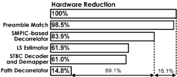
Fig. 20 illustrates the hardware reduction of the proposed channel estimator. Under the same system timing requirement, the direct implementation of the two-stage channel estimation requires about 1891.2 K gates excluding the FFT/IFFT module. By using our proposed scheme and architecture mentioned in Section IV, the hardware is reduced to only 281.2 K gates, which is 14.8% of the original design. The percentage value in the bar denotes the step-by-step hardware reduction of each block as compared with the overall direct implementation architecture. In the initialization stage, the preamble match uses only adders and shifters instead of multipliers, and the SMPIC-based decor-relator efficiently reduces the execution cycles by 9.63 times as compared to the MPIC-based decorrelator. Moreover, in the
Fig. 20. Hardware reduction of the proposed channel estimator.
tracking stage, the LS estimator only uses adders and multi-plexers instead of complex multipliers and dividers. The mentation of matrix inverse is avoided in both the direct imple-mentation and the proposed channel estimator. Since the Hes-sian matrix calculator is effectively merged into the path decor-relator, the path decorrelator further avoids a lot of execution cycles to compute each entry of the Hessian matrix and frees to use any multipliers and memory. Furthermore, the path decor-relator uses only adders and multiplexers instead of complex multipliers for matrix multiplication.
In summary, the interpolation-based channel estimation methods have the advantage of low implementation cost since they do not require FFT and IFFT to operate in transform do-main. However, their disadvantage is difficult to estimate CSI accurately under the situation of limited pilot subcarriers over doubly selective channels. In contrast, the two-stage channel estimation method has significant performance improvement in outdoor high-mobility environments, but it requires high hardware cost. For realizing the successful high-mobility STBC-OFDM systems, the proposed channel estimator effec-tively improves the design complexity of the two-stage channel estimation with acceptable hardware cost while keeping the performance of the two-stage channel estimation.
VI. CONCLUSION
In this paper, a channel estimator for STBC-OFDM systems in high-mobility wireless channels is proposed. The design applied in IEEE 802.16e system adopts a high performance two-stage channel estimation method to provide precise CSI. In addition, the implementation complexity of the proposed design is reduced by 85.2% as compared with the direct imple-mentation. When operating at of 120 and 240 km/hr with of 16 dB for QPSK modulation, the proposed design can achieve the BER of about 10 and 10 without using channel coding. As compared with interpolation-based channel estimation methods, our proposed scheme has significant performance improvements particularly in fast and selective fading channels. This channel estimator is implemented in 90 nm CMOS technology and operated at 83.3 MHz from 1 V supply voltage while drawing 43.71 mW. The design area costs 3.43 mm (859 604 gates) and that excluding the FFT/IFFT module is only 1.12 mm (281 226 gates), which is affordable in today’s baseband system on chip. In the future, the proposed channel estimator can be implemented to be scalable for dif-ferent FFT sizes as specified in IEEE 802.16e. With all these features, the proposed channel estimator can be applied to
[3] Y. H. Chung and S. M. Phoong, “Unitary precoders for ST-OFDM sys-tems using alamouti STBC,” IEEE Trans. Circuits Syst. I, Reg. Papers, vol. 55, no. 9, pp. 2860–2869, Oct. 2008.
[4] Local and Metropolitan Area Networks Part 16: Air Interface for Fixed Broadband Wireless Access Systems, IEEE Std 802.16-2004, Oct. 2004.
[5] Local and Metropolitan Area Networks Part 16: Air Interface for Fixed and Mobile Broadband Wireless Access Systems, IEEE Std 802.16e-2005, Feb. 2006.
[6] J. H. Park, M. K. Oh, and D. J. Park, “New channel estimation ex-ploiting reliable decision-feedback symbols for OFDM systems,” in Proc. Int. Conf. Commun., Jun. 2006, pp. 3046–3051.
[7] L. Deneire, P. Vandenameele, L. Van Der Perre, B. Gyselinckx, and M. Engels, “A low-complexity ML channel estimator for OFDM,” IEEE Trans. Commun., vol. 51, no. 2, pp. 135–140, Feb. 2003.
[8] M. Morelli and U. Mengali, “A comparison of pilot-aided channel es-timation methods for OFDM systems,” IEEE Trans. Signal Process., vol. 49, no. 12, pp. 3065–3073, Dec. 2001.
[9] M. L. Ku and C. C. Huang, “A derivation on the equivalence between Newton’s method and DF DFT-based method for channel estimation in OFDM systems,” IEEE Trans. Wireless Commun., vol. 7, no. 10, pp. 3982–3987, Oct. 2008.
[10] M. L. Ku and C. C. Huang, “A refined channel estimation method for STBC/OFDM systems in high-mobility wireless channels,” IEEE Trans. Wireless Commun., vol. 7, no. 11, pp. 4312–4320, Nov. 2008. [11] M. Speth, S. Fechtel, G. Fock, and H. Meyr, “Optimum receiver design
for OFDM-based broadband transmission part II: A case study,” IEEE Trans. Commun., vol. 49, no. 4, pp. 571–578, Apr. 2001.
[12] T. A. Lin and C. Y. Lee, “Predictive equalizer design for DVB-T system,” in Proc. IEEE Int. Symp. Circuits Syst., May 2005, vol. 2, pp. 940–943.
[13] K. Hwang, Computer Arithmetic, Principles, Architecture, and De-sign. New York: Wiley, 1979.
[14] S. Olariu, M. C. Pinotti, and S. Q. Zheng, “How to sort N items using a sorting network of fixed I/O size,” IEEE Trans. Parallel Distrib. Syst., vol. 10, no. 5, pp. 487–499, Mar. 1999.
[15] S. Olariu, M. C. Pinotti, and S. Q. Zheng, “An optimal hardware-al-gorithm for sorting using a fixed-size parallel sorting deveice,” IEEE Trans. Comput., vol. 49, no. 12, pp. 1310–1324, Dec. 2000. [16] C. Y. Huang, G. J. Yu, and B. D. Liu, “A hardware design approach for
merge-sorting network,” in Proc. IEEE Int. Symp. Circuits Syst., May 2001, vol. 4, pp. 534–537.
[17] K. E. Batcher, “On bitonic sorting networks,” in Proc. Int. Conf. Par-allel Process., 1990, pp. 376–378.
[18] L. Horvath, I. B. Dhaou, H. Tenhunen, and J. Isoaho, “A novel, high-speed, reconfigurable demapper-symbol deinterleaver architecture for DVB-T,” in Proc. IEEE Int. Symp. Circuits Syst., Jun. 1999, vol. 4, pp. 382–385.
[19] H. Y. Lee and I. C. Park, “Balanced binary-tree decomposition for area-efficient pipelined FFT processing,” IEEE Trans. Circuits Syst. I, Reg. Papers, vol. 54, no. 4, pp. 889–900, Apr. 2007.
[20] Y. W. Lin and C. Y. Lee, “Design of an FFT/IFFT processor for MIMO OFDM systems,” IEEE Trans. Circuits Syst. I, Reg. Papers, vol. 54, no. 4, pp. 807–815, Apr. 2007.
[21] M. Li, D. Novo, B. Bougard, L. Van Der Perre, and F. Catthoor, “Generic multi-phase software-pipelined partial-FFT on instruc-tion-level-parallel architectures and SDR baseband applications,” in Proc. Design Automation Test Eur., Mar. 2008, pp. 598–603. [22] Y. Chen, Y.-C. Tsao, Y.-W. Lin, C.-H. Lin, and C.-Y. Lee, “An
in-dexed-scaling pipelined FFT processor for OFDM-based WPAN ap-plications,” IEEE Trans. Circuits Syst. II, Exp. Briefs, vol. 55, no. 2, pp. 146–150, Feb. 2008.
She is currently pursuing the Ph.D. degree in the Department of Electronics Engineering, National Chiao Tung University, Hsinchu, Taiwan.
Her research interests include baseband signal processing, integrated circuit and system designs for wireless and mobile communications.
Meng-Lin Ku was born in Taoyuan, Taiwan. He
re-ceived the B.S., M.S., and Ph.D. degrees from the De-partment of Communication Engineering, National Chiao Tung University, Hsinchu, Taiwan, in 2002, 2003, and 2009, respectively.
His research interests are in the areas of wire-less and mobile communications, optimization for communication engineering, and statistical signal processing.
Shyh-Jye Jou received his B.S. degree in electrical
engineering from National Chen Kung University, Tainan, Taiwan, in 1982, and the M.S. and Ph.D. degrees in electronics from National Chiao Tung University, Hsinchu, Taiwan, in 1984 and 1988, respectively.
He joined Electrical Engineering Department, National Central University, Chung-Li, Taiwan, from 1990 to 2004 and became a Professor in 1997. Since 2004, he has been Professor of Electronics Engineering Department of National Chiao Tung University and became the Chairman from 2006. He was a visiting research Associate Professor in the Coordinated Science Laboratory at University of Illinois, Urbana-Champaign, during 1993–1994 academic years. In the summer of 2001, he was a visiting research consultant in the Communication Circuits and Systems Research Laboratory of Agere Systems. His research interests include design and analysis of high speed, low power mixed-signal integrated circuits, and communication integrated circuits and systems.
Dr. Jou served on the technical program committees in CICC, A-SSCC, ICCD, ISCAS, ASP-DAC, VLSI-DAT and other international conferences.
Chia-Chi Huang was born in Taiwan. He received
the B.S. degree in electrical engineering from Na-tional Taiwan University in 1977 and the M.S. and Ph.D. degrees in electrical engineering from the Uni-versity of California, Berkeley, in 1980 and 1984, re-spectively.
From 1984 to 1988, he was an RF and Communi-cation System Engineer with the Corporate Research and Development Center, General Electric Co., Sch-enectady, NY, where he worked on mobile radio com-munication system design. From 1989 to 1992, he was with the IBM T.J. Watson Research Center, Yorktown Heights, NY, as a research staff member, working on indoor radio communication system design. Since 1992, he has been with the Department of Communication Engineering, National Chiao Tung University, Hsinchu, Taiwan, currently as a Professor.