A Novel MPEG-4 Based Architecture for Internet Games
Wei-Teh Wang, Wan-Chun Ma, Kuo-Luen Perng, Meng-Jyi Shieh, Ming Ouhyoung
Communication and Multimedia Lab.,
Department of Computer Science and Information Engineering,
National Taiwan University, Taipei, Taiwan
E-Mail: {bearw, firebird, perng, feitian}@cmlab.csie.ntu.edu.tw, [email protected]
Abstract
The MPEG-4 is expected to become the information coding standard for future interactive multimedia applications. This paper intends to propose a novel architecture about applying the MPEG-4 technology to the design of Internet games, and we will show that most of the game modules can be implemented with the MPEG-4 modules.
1 Introduction
MPEG-4, a video, audio, and graphics compression standard, is one of the first object-oriented coding standard in the world. From technology point of view, it integrates natural (audio and video) and synthetic (scene and object description) contents into the bitstream and provides the capability of object reusability and scalability. We will introduce a whole new Internet game design style based on the MPEG-4 system.
Internet game development usually includes the following steps: game research and design, multimedia contents preparation, main program implementation and debugging and testing. Most of the game development bottleneck occurs at the step of main program implementation, especially in building a workable game system platform. Now we have a novel proposal for the Internet game system architecture. Since the MPEG-4 provides complete solutions of a multimedia system with high interactivity and networking capability, we can integrate a traditional game system into the MPEG-4. With the MPEG-4 architecture, developers don’t need to worry about the complicated design of the game system and can focus on the work of game story, scene constructing, object modeling and the game logic development.
According to this new game system design, for the game users, all the game data and personalized information is stored in a game server. So what they use to play a game can be an information appliance (personal computer, personal digital assistant, mobile phone, etc.) with a
any place with any device that contains a MPEG-4 browser. The architecture of MPEG-4 is scalable, which means it can send multimedia data with different quality depending on the network bandwidth and the device computing power. At the server side, by obtaining current network bandwidth and client device computing capability, the server automatically changes the bitstream with suitable quality (basic or enhanced) for the current operating environment. At the client side, the rendering module on a target device also can change the QoS parameters, such as frame per second, to cope with the device computing power. These system configuration methods are invoked to guarantee the game processing speed.
2 Introduction to Game Related MPEG-4
System
In this section, the MPEG-4 system is introduced first, and then the functionalities of each main module in the system will be addressed.
2.1 The Overview
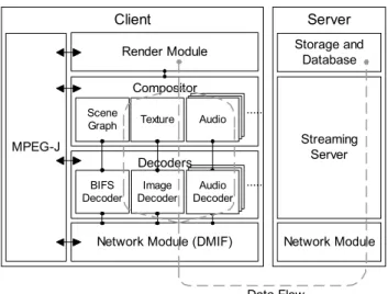
The MPEG-4 follows an object-based representation approach where an audio-visual scene is coded as a composition of objects, natural as well as synthetic, providing the first powerful hybrid playground. The objective of MPEG-4 is thus to provide an audio-visual representation standard supporting new ways of communication, remote multimedia access, and offering various interactive information services. MPEG-4 shall give an answer to the needs of application fields such as multimedia broadcasting, content-based audiovisual database access, games, video conferencing, advanced audiovisual communications, electronic business and so on. The MPEG-4 system architecture is shown in Fig. 1. The server is responsible for streaming, synchronization and stream management. The client receives and reconstructs the audiovisual scenes, and gives users the possibility to access, manipulate, or activate specific parts of the multimedia content.
Server Network Module Streaming Server Client MPEG-J Render Module Compositor Scene Graph
Network Module (DMIF)
Texture
Decoders
BIFS
Decoder DecoderImage
Storage and Database Audio ... ... Audio Decoder Data Flow
Figure 1: The MPEG-4 system architecture diagram. The
dot line indicates the data flow of the multimedia streaming data.
2.2 The Network Module
DMIF (Delivery Multimedia Integration Framework) is the data transmission layer in the MPEG-4 system. It provides the functionalities of bitstream transmission. The interface between DMIF and application is called DAI (DMIF Application Interface). The interface between DMIF and system network adapter is called DNI (DMIF Network Interface). DAI provides identical invocation methods to handle various kinds of service requirements, such as the access of different multimedia storage source and diverse network system. For supporting these functionalities of DAI, the implementation of DNI modules for each different network systems is needed.
In the design of DMIF, it combines the data transmission channel with a “session” together. The MPEG-4 service can be regarded as a session. Each session contains several data transmission channel, and each channel is responsible for delivering a kind of media information. For example, the service of playing a movie may contain video, audio, and text information channels. Besides, each channel can be assigned with different QoS (Quality of Service) parameters. Users can assign lower or higher quality to the channels that they want to discard or enhance.
2.3 The Decoder Module
Each transmission channel sends bitstream to the decoder module. It contains hybrid multimedia codec banks for decoding different audiovisual objects, such as BIFS (Binary Format for Scenes), audio and video objects.
2.4 The Render/Compositor Module
The MPEG-4 has already defined a high performance render module. The render module works in the client side and is used for presenting a scene description and its constituent multimedia objects to the output device, such as a display screen or speakers. A scene description follows a hierarchical structure that can be represented as a graph with no cycle. Each node in the hierarchical structure represents objects, actions and sensors. There are approximately one hundred node types defined in the MPEG-4 scene description language. Each node has different functionality, such as displaying 2D/3D objects and image textures, playing videos and audios, responding the user inputs, animating human face and body motions and so on. MPEG-4 scene description is an extension of the VRML specifications. Therefore, the normal way to build a MPEG-4 scene is to use VRML like description language. Using that can adjust all detail options to a scene node and do most of thing that has been specified in the specification. Fig. 2 shows the scene description of a KTV scene. Fig. 3 shows the KTV scene rendered by the MPEG-4 render module developed at our laboratory.
Scene
Furniture Room TV
Couch Table Roof Wall Display Button Speaker
Video Sensor Audio
Figure 2: The KTV Scene Description.
Figure 3: The KTV Scene displayed from the MPEG-4
render module developed at our laboratory.
The MPEG-J module is the key that makes MPEG-4 system interactive. It is programmable, and specifies APIs for interoperation of the other MPEG-4 modules with Java executable, which is called MPEGlet. In addition to the basic packages of the Java language (java.lang, java.io, java.util), the MPEG-J has a few categories of APIs that have been defined for different scopes. Developers may create MPEGlets with specialized functions by coding in Java language and using these APIs offered by the MPEG-J to access the various MPEG-4 system modules (Fig. 4.). We list these APIs and explain their functionality in the following.
1. Scene Graph APIs: The objective of invoking the Scene Graph APIs is to control the Scene Graph Manager for managing the scene displayed in the rendering module. The APIs includes the function of inserting or deleting a node, updating the node status and so on. If we want to add a new 3D object in the scene, we need to call the function of inserting a node of 3D object and a node of script to control the 3D object if needed. As a result, scene APIs provide developers the ability to access to the properties of a scene.
2. Net APIs: The objective of invoking the Net APIs is to control the Net Manager, which enable the ability to communicate with the server. The APIs includes sending and receiving messages to and from the server, retrieving the current network status and so on. 3. Resource APIs: The objective of invoking the
Resource APIs is to control the Resource Manager for regulation of performance. It provides a centralized facility for managing system recourses. It may retrieve the operating status of current system, such as the CPU or memory usage. This information can be sent back to the server. The server analyzes the client system status and adjusts the quality of the contents that the client receives for better processing performance in the client side. MPEG-J MPEG-J Application Network Manager Scene Graph Manager Resource Manager Render Module Scene Graph Network Module (DMIF) User Input/Output Device
Figure 4: This diagram shows the relationship between the
MPEG-J and the other main modules of the MPEG-4 system, where the arrow represents the access ability.
3
System Design and Implementation
Client Render Module
Server Storage and Database
Server Kernel Codec Client Kernel
Codec
DLLs
Network Module Network Module
Data Flow
Figure 5: A traditional Internet game system architecture
diagram. The dotted line indicates the data flow of the game information.
Through our survey, an ordinary Internet game system architecture should be similar to Fig. 5. The client program usually can be divided into three main parts: the render, the network, and the kernel module. The server program can be divided into two main parts: the network and the kernel modules. Generally speaking, the render module provides fast, realistic 2D/3D image, the network module ensures reliable, fault-tolerable network connection, and the kernel module is responsible for system control and programming logics processing. The server often needs to maintain client synchronization, manage the game processing status and provide the clients with reliable network connection. The client takes the job of sending, receiving scene information or commands to and from the server and representing interactive scenes to the game users.
Server Storage and Database
Server Kernel Codec Client Render Module MPEG-J Module Codec MPEGlets Network Module Network Module Data Flow
Figure 6: An Internet game system using the MPEG-4
technology. The blocks in gray represent the MPEG-4 modules that can be used in a game system.
If we apply MPEG-4 technology to the Internet game system architecture, the system will be like Fig. 6. The render and network modules provided by the MPEG-4 system can replace the same ones that should be developed otherwise. Besides, the kernel module becomes the MPEG-J module, which has a run time environment for MPEGlets to be executed on it. In Fig. 6, we are impressed by the fact that most of the game system modules are already provided by MPEG-4 system ones. Since the 3rd party software provider may offer the MPEG-4 system, for
game developers, the development time is saved, and they don’t need to worry about the system itself. The left jobs to them will be more concerned about the game application itself, such as developing game logics.
4 Issues on MPEG-4 based Game
Implementation
Now we’ll bring up some important issues for build MPEG-4 games.
4.1 Creating Compatible Multimedia Files and Scenes to use in the MPEG-4 Games
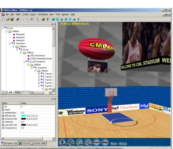
Figure 7: The MPEG-4 Scene Editor developed by our
laboratory.
In general, the game artists still can create multimedia contents with their favorite software. For example, they can use modeling software such as 3D Studio Max, LightWave for 3D object modeling. However, all scene and 3D objects should be saved in BIFS format to cope with the MPEG-4. Therefore, it is necessary to provide an authoring tool. Our laboratory has developed a MPEG-4 scene-authoring tool (Fig. 7). In order to facilitate the scene construction, we have developed a MPEG-4 Scene Editor to help people edit MPEG-4 scenes. We believe that providing such as a MPEG-4 context-produced tool is meaningful for pushing MPEG-4 standard to be widely adopted. This editor itself can be divided into three parts according to their functionalities:
1. Scene Tree Structure Editor: Using the Scene Tree Structure Editor can modify all detailed options in a scene node and do most of thing that has been specified in the specification.
2. Scene Node Properties Editor: A scene node consists of many fields. Each field has its own data type, such that “SFInt32”, “SFColor” and so on. This editor helps authors access these node fields.
3. Event Editor: Interactivity mechanisms are integrated with the scene description information, in the form of linked event sources and targets (routes) as well as sensors (special nodes that can trigger events based on specific conditions). These event sources and targets are part of the scene description nodes, and thus allow tight coupling of dynamic and interactive behavior with a specific scene at hand. 4.2 Games Design and Implementation with
MPEGlet
There are many MPEGlets to be implemented in order to achieve lots of functionalities in a Internet game system, such as object movement calculation, user event handler, syncronization and so on.
We can simulate simple and regular movements by inserting script nodes in a scene tree, such as object vibration. As for complex movements, such as physical phenomenon, we need to use MPEGlet for precise object position calculation.
For user interaction, we need to use the sensor node and MPEGlet together. The sensor node is defined in the MPEG-4, which is used for capturing interactive messages from a user, such as mouse movement and mouse clicks. After a specific sensor node is triggered, the MPEGlet, which is responsible for the user messages, handles this event and invokes corresponding predefined functions. For example, if a user makes a forward movement, the sensor node will notify the MPEGlet immediately. Then the MPEGlet sends a user event message to the server. After the server receives and changes the current position of the player, it sends an acknowledgement message back to the client. The MPEGlet finally updates the scene graph and finishes the whole movement process.
4.3 Game Server Design
MPEG-4 only defines the streaming mechanism and implementation, but has no definite comments on the server kernel design. So developers can create their own server kernel with any suitable ideas, such as using a virtual machine for running game logic components.
Most of the online games are only designed for the personal computers with specific operating system. Users cannot play the same game in other devices or platforms. With the MPEG-4 based architecture of Internet game, we can extend the game operating environment to mobile devices, such as personal digital assistant, mobile phone, and so on. In our design, users can a play game with any devices, as long as it supports the MPEG-4 browser. Base on the architecture, we can assume that all the data which is used in the game is stored in the server side, so there is no need for local installation or saving personal data issues. The users can just use a MPEG-4 browser to connect to the server and start to play the game. For different game operating environment, especially different computing power and network bandwidth, the game itself must be scalable so that it can provides the best quality for a game. For the networking issue, MPEG-4 itself defines a set of methods to control the data transmission in different network bandwidth, which we have discussed it in previous section. For the computing issues, game developers need to provide multimedia content with different quality, such as basic and enhanced 3D models, texture images, videos and so on. If the user plays the game with a low computing power device, such as personal digital assistant, he may choose the basic configuration for faster processing speed. Similarly, if the user plays the game with a personal computer, he may choose the enhanced configuration for more fantastic effects. Fig. 8 shows the diagram of the total solution of the game environment operation.
WAN Ethernet Wireless WAN Wirelees LAN MPEG-4 Game Server Desktops Handhelds Moblie Phones Enhanced Quality Data Streams
Basic Quality Data Streams
Low Quality Data Streams
Access Point
Comm. Tower
Figure 8: The MPEG-4 game environment operation
diagram. .
During the past two years, our laboratory have emphasized on the MPEG-4 system implementation. The authors have completed several MPEG-4 system modules,
MPEG-4 streaming server. We will continue to develop and enhance this system in MPEG-4 architecture from the interactive aspect. The MPEG-J module will be the focus in our next development project. We now try to bring game technologies into the MPEG-4 system, and we are convinced that it has opened a novel application area.
6 Bibliography
[1] ISO/IEC 14496-1, Information Technology – Coding of audio-visual objects – Part 1: Systems.
[2] ISO/IEC 14496-1/FDAM1:2000(E), Information Technology – Coding of audio-visual objects – Part 1: Systems.
[3] ISO/IEC 13818, Information Technology – Generic Coding of Moving Pictures and Associated Audio Information – Part 2: Video, Part 3: Audio, International Organization for Standardization, 1994.
[4] Kuo-Luen Perng, Yu-Chung Lee, Wei-Ru Chen, Yu-Li Huang, An-Lung Teng, Ming Ouhyoung “A Render Module of MPEG-4 System Based on VRML97 for Virtual and Natural Scene Integration”, Proceedings of the 10th. International Conference on Artificial Reality and Teleexistence (ICAT2000), October 2000, pp. 201-206.
[5] Yi-Shin Tung, Ja-Ling Wu, Chia-Chiang Ho “Architecture Design of an MPEG-4 System”, Proceedings of IEEE International Conference on Consumer Electronics, June 2000 (ICCE 2000), pp. 120-121.
[6] Deng-Rung Liu, Meng-Jyi Shieh, Yu-Chung Lee, Wen-Chin Chen “On the Design and Implementation of an MPEG-4 Scene Editor”, Proceedings of IEEE International Conference on Consumer Electronics, June 2000 (ICCE 2000), pp. 120-121.