國
立
交
通
大
學
資訊學院資訊科技(IT)產業研發碩士班
碩
士
論
文
使用視訊模型從單一影像自動產生有動態
嘴形動作的虛擬人臉之研究
A Study on Automatic Creation of Virtual Faces with Dynamic
Mouth Movements from Single Images Using Video Models
研 究 生:黃巧均
指導教授:蔡文祥 教授
使用視訊模型從單一影像自動產生有動態
嘴形動作的虛擬人臉之研究
A Study on Automatic Creation of Virtual Faces with Dynamic
Mouth Movements from Single Images Using Video Models
研 究 生:黃巧均 Student:Chiao-Chun Huang
指導教授:蔡文祥 Advisor:Wen-Hsiang Tsai
國 立 交 通 大 學
資訊學院資訊科技(IT)產業研發碩士班
碩 士 論 文
A ThesisSubmitted to College of Computer Science National Chiao Tung University in partial Fulfillment of the Requirements
for the Degree of Master
in
Industrial Technology R & D Master Program on Computer Science and Engineering
June 2009
Hsinchu, Taiwan, Republic of China
使用視訊模型從單一影像自動產生
有動態嘴形動作的虛擬人臉之研究
研究生: 黃巧均 指導教授: 蔡文祥 博士
國立交通大學資訊學院產業研發碩士班
摘要
本論文提出一個由單一影像自動產生有動態嘴型動作的虛擬人臉之系統。此 系統包含了三個流程:視訊模型分析、臉部特徵點追蹤、虛擬人臉產生。由本系 統產生的動態虛擬人臉系列與所輸入單一影像中之人臉皆相同。為了產生虛擬人 臉,我們提出一個含二十六個特徵點的嘴形模型。首先我們分離事先錄製的視訊 模型之語音成分,再將視訊模型分解成多張連續影像。之後,再半自動地取得所 輸入單一影像及視訊模型的第一張影像中的臉部特徵點。接著,我們提出了兩種 嘴部狀態和三種閉嘴嘴形,以及一個影像對應技術,並用以分析視訊模型中的嘴 型動作及追蹤其臉部特徵點。此技術使用相關係數求得各特徵點之最佳對應位 置,並依不同嘴部狀態而動態改變視窗大小。為了取得正確的臉部特徵點,每當 偵測到閉嘴嘴形時,我們即校正特徵點至正確位置。接著我們利用一個形變 (morphing)技術讓所輸入單一影像及視訊模型中之嘴形動作同步化,使得虛擬人 臉看起來像與視訊模型中的人一樣說出相同的話。而我們所指定的臉部控制點亦 能調整虛擬人臉之嘴部大小及下巴位置,使得人臉在講話過程中看起來更加地自 然。良好的實驗結果證明了本論文所提方法之可行性。 iii
A Study on Automatic Creation of Virtual Faces with
Dynamic Mouth Movements from Single Images Using
Video Models
Student: Chiao-Chun Huang Advisor: Dr. Wen-Hsiang Tsai
Industrial Technology R & D Master Program of CS Colleges
National Chiao Tung University
ABSTRACT
In this study, a system for automatic creation of virtual talking faces with dynamic mouth movement using a single image of a human face and a video model of a real talking face is proposed, which includes three processes: video model analysis, feature point tracking, and virtual face creation. The dynamic virtual face series created by the system is the same as the input image. First, a mouth model of 26 feature points is proposed for virtual face creation. Two mouth states and three closed-mouth shapes are proposed for video analysis to obtain mouth movements in the real-face video model. For feature point tracking, an image matching technique using correlation coefficients with dynamically changed window sizes is proposed. The window sizes are changed according to the mouth states. A technique for correction of the feature point locations of a closed mouth is proposed. A mouth shape morphing technique is used for synchronizing the mouth shapes of the input image with the video model, yielding the effect that the created virtual faces look like speaking the same words as the person in the video model. A concept of assigning facial control points is applied to create the virtual faces with scaled mouth sizes. Good experimental results show the feasibility and applicability of the proposed method.
ACKNOWLEDGEMENTS
The author is in hearty appreciation of the continuous guidance, discussions, support, and encouragement received from his advisor, Dr. Wen-Hsiang Tsai, not only in the development of this thesis, but also in every aspect of her personal growth.
Thanks are due to Mr. Tsung-Yuan Liu, Mr. Chih-Jen Wu, Mr. Che-Wei Lee, Mr. Guo-Feng Yang, Mr. Chun-Pei Chang, Miss Shu-Hung Hung, Miss Chin-Ting Yang, Mr. Jian-Yuan Wang, Miss Mei-Fen Chen, and Mr. Yi-Chen Lai for their valuable discussions, suggestions, and encouragement. Appreciation is also given to the colleagues of the Computer Vision Laboratory in the Institute of Computer Science and Engineering at National Chiao Tung University for their suggestions and help during her thesis study.
Finally, the author also extends her profound thanks to her family for their lasting love, care, and encouragement. She dedicates this dissertation to her parents.
iv
CONTENTS
ABSTRACT (in Chinese) ... i
ABSTRACT (in English) ... ii
ACKNOWLEDGEMENTS ... iii
CONTENTS ... iv
LIST OF FIGURES ... vii
Chapter 1 Introduction ... 1
1.1 Motivation ... 1
1.2 Survey of Related Studies ... 2
1.2.1 Review of Related Studies ... 2
1.2.2 Review of Image Matching Technique by the Use of Correlation Coefficients ... 4
1.2.3 Review of Morphing Techniques ... 4
1.3 Overview of Proposed Method ... 7
1.3.1 Definitions of Terms ... 7
1.3.2 Assumptions ... 9
1.3.3 Brief Descriptions of Proposed Method ... 9
1.4 Contributions ... 10
1.5 Thesis Organization ... 11
Chapter 2 Overview of Proposed Method for Virtual Face Creation ... 12
2.1 Idea of Proposed Method ... 12
2.2 Review of Adopted Face Model ... 13
2.3 Construction of Mouth Model and Uses of Mouth Features ... 16
2.3.1 Construction of Mouth Model Based on Adapted Face Model ... 16
2.3.2 Mouth Feature Regions ... 17
2.3.3 Mouth Control Points ... 18
2.4 Virtual-Face Creation Process from Sequential Images ... 18
Chapter 3
Tracking of Facial Feature Points ... 21
3.1 Idea of Proposed Techniques ... 21
3.1.1 Necessity of Changes of Window Sizes ... 21
3.1.2 Necessity of Corrections of Facial Feature Point Positions... 22
3.1.3 Tracking Process ... 24
3.2 Definition of Mouth States Using Mouth Size Changing Information ... 25
v
3.2.2 Detection of Mouth states ... 26
3.3 Image Matching Using Correlation Coefficients Using Dynamically Changed Window Size ... 28
3.3.1 Initial Search Window Size and Content Window Size ... 29
3.3.2 Content Window Size of Opening State ... 31
3.3.3 Content Window Size of Closing State ... 32
3.3.4 Balancing Feature Point Position by Changing Search Window Size .... 32
3.4 Detection of Closed-Mouth Shapes ... 34
3.4.1 Type-1 Closed-Mouth Shape ... 36
3.4.2 Type-2 Closed-Mouth Shape ... 36
3.4.3 Type-3 Closed-Mouth Shape ... 37
3.5 Correction of Feature Point Locations of Closed Mouth ... 37
3.5.1 Idea of Correction in Green Channel ... 38
3.5.2 Edge Detection and Bi-level Thresholding in Green Channel ... 38
3.5.3 Correction Process ... 40
3.6 Experimental Results ... 41
Chapter 4
Creation of Virtual Faces with Dynamic Mouth Movements 42
4.1 Idea of Proposed Technique ... 424.1.1 Mouth Shape Division ... 42
4.1.2 Main Steps of Proposed Virtual Face Creation Process ... 43
4.2 Creation of Real-Face Video Model ... 45
4.2.1 Criteria for Real-Face Video Model Creation... 45
4.2.2 Locating Feature Points in Real-Face Images ... 45
4.2.3 Real-Face Video Model Creation Process ... 46
4.3 Mouth Shape Morphing with Bilinear Transformation ... 47
4.3.1 Review of Bilinear Transformation ... 47
4.3.2 Review of Inverse Bilinear Transformation ... 49
4.3.3 Proposed Mouth Shape Morphing Process ... 50
4.4 Creation of Virtual-Face Image Sequences ... 52
4.4.1 Generation of Virtual-Mouth Images ... 52
4.4.2 Scaling of Mouth Sizes by Real-Face Model ... 53
4.4.3 Extraction of Mouth Regions from Scaled- Mouth Images... 58
4.4.4 Gap Filling and Boundary Smoothing ... 62
4.4.5 Creation of Single Virtual-Face Images ... 63
4.5 Experimental Results ... 64
Chapter 5
Experimental Results and Discussion ... 66
5.1 Experimental Results ... 66
vi
Chapter 6 Conclusions and Suggestions for Future Works ... 74
6.1 Conclusions ... 74
6.2 Suggestions for Future Works ... 75
vii
LIST OF FIGURES
Figure 1.1 Single line-pair transformation. ... 6
Figure 1.2 Multiple line-pair transformation. ... 6
Figure 1.3 Single line-pair transformation. The original image is in (a), and
the line is rotated in (b), translated in(c) and scaled in (d). ... 6
Figure 1.4 Multiple line-pair transformation. (a) The original image. (b) An
example of using two line pairs. ... 6
Figure 1.5 Bilinear transformation scheme. ... 7
Figure 2.1 84 feature points in MPEG-4. ... 14
Figure 2.2 FAPUs in MPEG-4. ... 14
Figure 2.3 A adapted face model. (a) Proposed 72 feature points. (b)
Proposed FAPUs in Chen and Tsai [1]. ... 15
Figure 2.4 Mouth Feature Points used in the proposed method ... 17
Figure 2.5 Entire proposed mouth model. The blue dots in the model are
added to help morphing, and the red dots are control points. ... 17
Figure 2.6 Mouth feature regions used in the proposed method. (a) Bottom
part of a virtual face. (b) The mouth region. (c) The skin region
outside the mouth. (d) The lip region. (e) The teeth region. ... 18
Figure 2.7 Stages of proposed virtual face creation from sequential images.20
Figure 3.1 Examples of the changed and unchanged window sizes. (a) The
69
thframe of a video using a constant window size. (b) The 72
thframe
of a video using a constant window size. (c) The 69
thframe of a video
using dynamically changed window sizes. (d) The 72
thframe of a
video using dynamically changed window sizes. ... 22
Figure 3.2 Facial feature point tracking result of mouth shape of a person
saying “u.” (a) Tracking result of 34
thframe of a video. (b) Tracking
result of 37
thframe of a video. (c) Tracking result of 40
thframe of a
video. (d) Tracking result of 43
thframe of a video. (e) Connecting the
points in the 43
thframe of a video. (f) The 43
thframe of a video after
correction using proposed method. ... 23
Figure 3.3 Flowchart of the proposed feature point tracking method. ... 24
Figure 3.4 The FAPUs in the proposed system. ... 25
Figure 3.5 A line chart of the frames of the closing state from the 32
ththrough
the 46
thframes of the video model. ... 26
Figure 3.6 An mechanics of image matching using dynamically changed
window size. ... 29
viii
Figure 3.7 An illustration of initial window size. (a) Initial search window
size. (b) Initial content window size. ... 30
Figure 3.8 An illustration of content window size of opening state. ... 31
Figure 3.9 An illustration of content window size of closing state. ... 32
Figure 3.10 Illustration of balancing feature point positions by changing
search window size. ... 33
Figure 3.11 A illustration of setting the value of X
startand X
end. ... 34
Figure 3.12 An example of closed-mouth shapes. The mouth is opening. .... 35
Figure 3.13 Diagrams of type-1 closed-mouth shape. (a) The left points of
inner mouth. (b) An example of type-1 closed-mouth shape. ... 36
Figure 3.14 Diagrams of type-2 closed-mouth shape. (a) The right points of
inner mouth. (b) An example of type-2 closed-mouth shape. ... 37
Figure 3.15 Diagrams of type-3 closed-mouth shape. (a) The middle points of
inner mouth. (b) An example of type-3 closed-mouth shape. ... 37
Figure 3.16 The RGB channel images of partial part of 15
thframe of a video
model. (a) Red-channel image. (b) Green-channel image. (c)
Blue-channel image. ... 38
Figure 3.17 Sobel operators. ... 39
Figure 3.18 A resulting sequence of tracking feature points in a video clip of
speaking “everybody” in Chinese. ... 41
Figure 4.1 Proposed mouth shape division scheme which divides the mouth
shape into twenty-seven overlapping quadrilaterals. ... 43
Figure 4.2 The flowchart of proposed virtual face creation from image
sequences. ... 44
Figure 4.3 The mouth images. (a) The mouth image of the input image. (b)
The mouth image of a frame of the video model. (c) The
virtual-mouth image is created from (a) by warping it to (b). (d) The
virtual-mouth image is a scaled mouth image from (c) and is
integrated with (a). ... 47
Figure 4.4 The proposed bilinear transformation in Gomes, et al. [14]. ... 48
Figure 4.5 The proposed inverse bilinear transformation in Gomes, et al. [14].
... 49
Figure 4.6 The proposed transformations between two arbitrary quadrilaterals
in Gomes, et al. [14]. ... 50
Figure 4.7 Generation of a virtual-mouth image. (a) An Angelina Jolie’s
photo as the single input image. (b) The real-face image which is the
50
thframe of the video model. (c) The virtual-mouth image. ... 53
ix
video model. (b) The 85
thframe of the video model. (c) A single input
image. (d) The virtual-mouth image. (e) The virtual-mouth image
scaled by (c). (f) The virtual-mouth image with a scaled mouth. ... 53
Figure 4.9 Proposed mouth shape division scheme used to scale the mouth
size, which divides the mouth shape into 12overlapping quadrilaterals,
including quadrilaterals DEBA and EFCB. ... 55
Figure 4.10 Illustration of the scaled mouth shape when the mouth width of
the current frame is smaller than that in the first frame in the video
model. (a) The virtual-mouth image containing the mouth and the
skins near it. (b) Proposed mouth shape division scheme used to scale
the mouth size. ... 56
Figure 4.11 The facial images. (a) The scaled-mouth image created from the
85
thframe of the video model. (b) The image B. (c) The image B′. (d)
The mouth region of (a). ... 59
Figure 4.12 Illustration of the range of the mouth and the mouth region. .... 60
Figure 4.13 The illustration of gap filling and boundary smoothing. (a) The
B
smoothimage. (b) The mouth region after filling and smoothing. ... 62
Figure 4.14 Illustration of the virtual face creation. ... 63
Figure 4.15 A real-face video model of speaking “teacher” in Chinese. ... 64
Figure 4.16 A resulting sequence of virtual face creation by using the video
model in Figure 4.15. ... 65
Figure 5.1 Illustration of the 150 frames extracted from the video. ... 66
Figure 5.2 Illustration of the feature point positions. (a) The feature points
were located by enlarging the image. (b) The horizontally symmetric
points. (c) The adjusted feature points. ... 67
Figure 5.3 Choosing an input image and feature point coordinates of it. ... 68
Figure 5.4 The feature point tracking process. ... 69
Figure 5.5 The intermediate result of virtual face creation process. ... 69
Figure 5.6 The result of virtual face creation process by using Angelina
Jolie’s photo as the input image. ... 70
Figure 5.7 The result of virtual face creation process by using Liv Tyler’s
photo as the input image. ... 71
Figure 5.8 The result of virtual face creation process by using Neng-Jing Yi’s
photo as the input image. ... 72
1
Chapter 1
Introduction
1.1 Motivation
In recent years, people are used to communicate and share multimedia files through the computer network. With the development of the high-speed Internet, more and more people upload video clips and share them through blogs, emails, and websites such as YouTube. Also, people can now watch high-quality videos online.
The contents of videos are of wide variety, including videos for teaching, life recording, security monitoring, etc. Some people just want to share their experiences and wish not to show up in the video, so that they may try to record voices only or use cartoon-like faces instead of showing their own faces in the transmitted video. However, human faces and speeches created artificially in such kinds of videos are still unnatural.
It is usually desired to create more human-like faces which make virtual-face related videos friendlier. This topic is called virtual talking face creation, and many researches on this topic concentrate on how to create more realistic faces. A virtual talking face can be used to reflect facial expressions, including emotional looks and mouth movements.
2
image frames in a given video so that we can control the feature points to generate different kinds of virtual expressions. Real-time systems detect the feature points in the first frame of videos, and track them in the other frames. In this way, we can have the feature points of each frame and can create sequential virtual faces with motions. Also, traditional systems create virtual faces by the use of matching input voices (or texts) and visemes with reference data in models. Such voice and text analyses usually are sensitive to noise in the recording environment.
In this study, we want to design an automatic system for creating virtual faces with dynamical mouth movements. And we will not deal with voice and text analyses but only use facial image information. The input to this system is a facial image, and the output is an image sequence representing a human head talking process.
1.2 Survey of Related Studies
In this section, several virtual face creation techniques are reviewed in Section 1.2.1. And an image matching technique based on the correlation coefficient measure is reviewed in Section1.2.2. And several morphing techniques are reviewed in Section 1.2.3 finally.
1.2.1 Review of Related Studies
Many studies about virtual face creation have been conducted. Generally speaking, there are two main approaches to it, but both of them should gather the feature points of facial images before creating virtual faces with different kinds of expressions.
The first approach needs to define some viseme types and phoneme combinations, which have mapping relations. And it needs to analyze voices or texts for mapping the analysis result to one of the phoneme combinations. Because each of
3
them has a relation to one viseme, we can get a corresponding viseme type. Then the shape of facial images is warped to the shape of the corresponding viseme, and a cartoon-like face with the viseme shape is generated by a computer graphic technique [1-10].
Chen and Tsai [1] designed a system to generate cartoon faces automatically by the use of facial feature point detection, speech analysis, and curve drawing techniques. Talking cartoon faces are generated from image sequences. The Video Rewrite designed by Bregler, Covell, and Slaney [6] is a system proposed to rewrite videos with audios. It automatically labels the phonemes in training data and in new soundtracks. Its video models are defined by mapping phonemes in the soundtrack to the training data, which include chin, mouth, and jaw. To rewrite the video, it combines the video model with the original video. Cosatto [7] presented a system that produces photo-realistic computer animations of a person talking in general text. In Lin et al. [8], a lifelike talking head system was proposed. The talking head is driven by speaker independent speech recognition. In Nedel [9], the use of a speech recognition technique to segment the lip features extracted from a video on a phoneme by phoneme basis was proposed. MikeTalk, presented in Ezzat and Poggio [10], is a text-to-audiovisual speech synthesizer which converts input text into an audiovisual speech stream. It morphs every corresponding viseme to acquire a smoothing transition result.
The second approach has two differences from the first approach. One is not to implement the voice and text analyses. The other is the use of expression mapping instead of phoneme mapping. The basic process is to map a facial image to an expression, warp or morph it to the corresponding expression, and draw a cartoon-like face [11-12].
4
real time is presented in Buck et al. [11]. Given an annotated set of hand-drawn faces for various expressions, their algorithm performs multi-way morphing to generate real-time animation that mimics the expressions of a user.
Zhang et al. [12] provided a way for automatic synthesis of the corresponding expression image which has photorealistic and natural looking expression details.
1.2.2 Review of Image Matching Technique by the
Use of Correlation Coefficients
Gonzalez and Woods [13] introduced an image matching technique via the use of the correlation coefficient. It finds a subimage w ,
( )
x y within an image f( )
x,y where the size of f is bigger than w. The correlation coefficient is defined as( )
[
( )
]
[
(
) (
)
]
( )
[
]
[
(
) (
)
]
2 1 2 2 , , , , , , , ⎭ ⎬ ⎫ ⎩ ⎨ ⎧ − + + − + + + + − + + − =∑∑
∑∑
∑∑
∑∑
s t s t s t s t t y s x f t y s x f w t s w t y s x f t y s x f w t s w y x γ , (1. 1)where w is the average value of the pixels in w, f is the average value of f in the region coincident with the current location of w.
As x and y vary, w moves around inside the area of f. The best match position has the maximum value of γ.
1.2.3 Review of Morphing Techniques
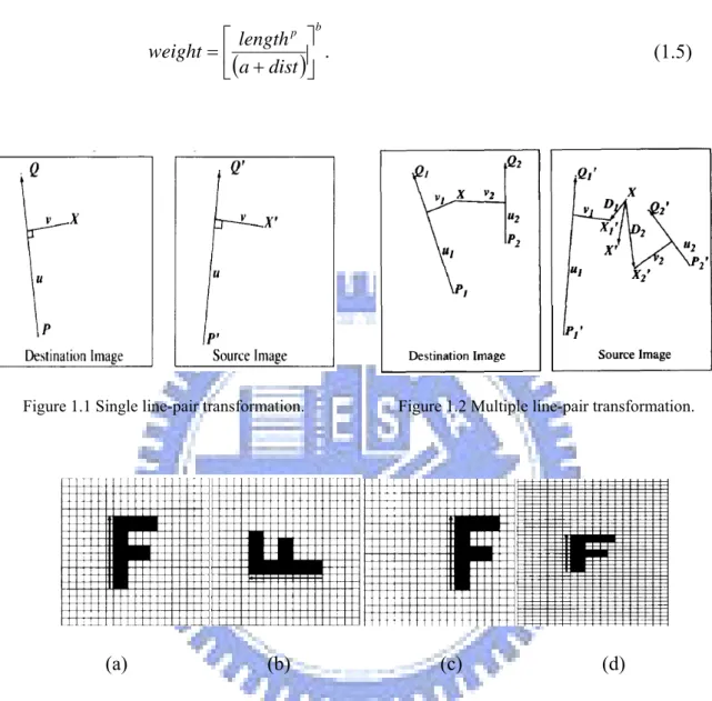
Beier and Neely [15] proposed two transformation techniques for morphing:
single line pair and multiple line pairs. They defined a coordinate mapping from a
destination image pixel X to a source image pixel X′ with respect to a line PQ in the destination image and a line P′Q′ in the source image, respectively. As shown in Figures 1.1 and 1.2, let the value u be the position along the line PQ, and v be the
5
distance from PQ to the image pixel X. Figures 1.3 and 1.4 show some examples of these transformations which are described as follows.
(1) Transformation of single line pair ---
For each pixel X in the destination image, perform the following steps. (i) Find the corresponding values of u and v according to the following
equations:
(
) (
)
2 P Q P Q P X u − − ⋅ − = ; (1.2)(
)
(
)
P Q P Q lar Perpendicu P X v − − ⋅ − = , (1.3)where Perpendicular() returns the vector perpendicular to, and of the same length as, the input vector.
(ii) Find X′ in the source image for these values of u and v according to the following equation:
(
)
' '(
' ')
' ' ' ' P Q P Q lar Perpendicu v P Q u P X − − ⋅ + − ⋅ + = . (1.4)(iii) Set the mapping Destination Image(X) = Source Image(X′). (2) Transformation of multiple line pairs ---
For each pixel X in the destination image, perform the following steps. (i) For each line PiQi, perform Steps (ii) to (vi);
(ii) Find the corresponding values of u and v according to Equations (1.2) and (1.3).
(iii) Find X′ in the source image based on these values of u and v, and the line Pi′Qi′ according to Equation (1.4).
(iv) Calculate the displacement Di = X − X′.
6
(vi) Compute the following weight where a, b, and p are user-defined constants :
(
)
b p dist a length weight ⎥ ⎦ ⎤ ⎢ ⎣ ⎡ + = . (1.5)Figure 1.1 Single line-pair transformation. Figure 1.2 Multiple line-pair transformation.
(a) (b) (c) (d)
Figure 1.3 Single line-pair transformation. The original image is in (a), and the line is rotated in (b), translated in(c) and scaled in (d).
(a) (b)
Figure 1.4 Multiple line-pair transformation. (a) The original image. (b) An example of using two line pairs.
7
Gomes, et al. [14] proposed a bilinear transformation to warp unit squares into quadrilaterals, as shown in Figure 1.5, and an inverse bilinear transformation to warp quadrilaterals to unit squares. We will describe the details in Chapter 4.
Figure 1.5 Bilinear transformation scheme.
1.3 Overview of Proposed Method
An overview of the proposed method is described in this section. First, some definitions of terms used in this study are introduced in Section 1.3.1. And several assumptions made for this study are listed in Section 1.3.2. Finally a brief description of the proposed method is given in Section 1.3.3.
1.3.1 Definitions of Terms
The definitions of some terms used in this study are as follows.
(1) Neutral Face: MPEG-4 specifies some conditions for a head in its neutral state
[16] as follows.
1. The gaze is in the direction of the Z-axis. 2. All face muscles are relaxed.
8
4. The pupil is one third of the iris diameter. 5. The lips are in contact.
6. The line of the lips is horizontal and at the same height of the lip corners. 7. The mouth is closed and the upper teeth touch the lower ones.
8. The tongue is flat and horizontal with the tip of the tongue touching the boundary between the upper and lower teeth.
In this thesis, a face with a normal expression is called a neutral face.
(2) Neutral Facial Image: A neutral facial image is an image with a frontal and
straight neutral face in it.
(3) Facial Features: In the proposed system, we care about several features of the
face, including hair, face, eyebrows, eyes, nose, mouth, and ears of each facial image.
(4) Facial Action Units (FAUs): Facial Action Coding System (FACS) [18] defines
66 basic Facial Action Units (FAUs). The major part of FAUs represents primary movements of facial muscles in action such as raising eyebrows, blinking, and talking. Other FAUs represent head and eye movements.
(5) Facial Expression: A facial expression is a facial aspect representative of
feeling. Here, facial expressions include emotions and lip movements. Facial expressions can be described as combinations of FAUs.
(6) FAPUs: Facial animation parameter units (FAPUs) are the fractions of the
distances between some facial features, like eye separation, mouth width, and so on.
(7) Real-Face Video Model: Each real-face video model has a person in it, either
male or female, whose talking progress is recorded by a camera. The models are used to create final image sequences.
9
points of the real-face model. They are used to control many features of the models, like eyebrow raising, eye opening, mouth movement, head tilting, and head turning. In this study, they used to control mouth movements.
(9) Mouth Region: a mouth region is a part of faces, which nears the mouth. Some
variable facial features may be pasted onto it to form final image sequences.
1.3.2 Assumptions
In the proposed system, real-face video models are captured by a camera. In a real situation, it is not a simple task to track real faces which have a smooth contour. We must make some assumptions and restrictions in this study to reduce the complexity, which are described as follows.
(1) The lighting of the environment is constant.
(2) The face of a video model always faces the camera and is located in the middle of the field of view of the camera.
(3) The head in a video model does not move quickly.
(4) The video models and facial images have good resolutions (higher than 640×480).
(5) The percentage of a face area in a facial image is over 70%. (6) The mouth in a video model has a sharp contour.
(7) The speech is spoken with a medium speed.
1.3.3 Brief Descriptions of Proposed Method
In this study, the proposed system includes six main processes: video recording, feature point locating, feature point tracking, mouth shape morphing, mouth region extraction, and virtual face creation.
10
The first process is video recording, from which we can get a real-face video model. Secondly, we locate manually the feature points in the first frame of a given video and in an input facial image. The reason why we locate them manually is that it is not easy to detect automatically the feature points of a mouth with a smooth curve edge. Then, we track the feature points from one frame to the next. After the tracking process, we have all feature points of each frame of the video model, so we can morph the input facial image to every frame of the video model and obtain an image sequence.
The process of mouth region extraction mainly takes the bottom face part out from the image sequence below the nose and removes the skin of the neck part. At the last step, the mouth regions and the input facial image are integrated to create the result.
1.4 Contributions
Some major contributions of this study are listed as follows.
(1) A system for automatic creation of virtual faces with mouth movements is proposed.
(2) A system for creating virtual faces without voice and text analyses is proposed. (3) A technique using a facial image to fit a sequence of other facial images is
proposed.
(4) Some techniques for tracking feature points are proposed. (5) A technique for correcting feature points is proposed.
(6) A technique to create virtual teeth and tongues for closed mouth facial images is proposed.
(7) A technique to generate dynamic mouth movements is proposed.
11
1.5 Thesis Organization
The remainder of the thesis is organized as follows. Chapter 2 describes an overview of the proposed technique for virtual face creation. Chapter 3 presents the proposed technique for tracking facial feature points automatically. Chapter 4 describes the proposed technique of creation of virtual faces with dynamic mouth movements. In Chapter 5, some experimental results and discussions are described. Finally, conclusions and suggestions for future works are included in Chapter 6.
12
Chapter 2
Overview of Proposed Method for
Virtual Face Creation
2.1 Idea of Proposed Method
The virtual face creation system proposed in this study is like a black box. The input to it is a single facial image and the output is a facial image sequence. In other words, it is like to make a human face in a single image to laugh or talk in an artificially-created image sequence or video. We use real-face video models to achieve this goal, so the input image will do the same mouth movements as the models. The system is described in more detail in the following.
First, we propose a technique to analyze video models to get the mouth movement information. Because some mouth movements have quite different mouth shapes from others, such as those of “u” and “o,” it is not easy to conduct image matching for such mouth movements. Besides, image matching has another problem which occurs when a closed mouth is opening or when an opened mouth is closing, that is, the teeth will appear or disappear alternatively to interfere with the correctness of image matching. So we propose a novel image matching technique to deal with such a problem of interference coming from changed mouth-shape and teeth appearances.
After creating a virtual mouth by a morphing technique, it may be bigger or smaller than the mouth of the input image which has a closed mouth. For example, the
13
virtual mouth will be bigger than the mouth of the input image when a person in the video model says the letter “a” for which the mouth is opening and the chin is moving down. If we just paste the mouths on the input image, the resulting image will have clear edges at the pasted mouth boundary. So we propose a technique to extract the mouth region and smooth its edges before integrating the mouth with the input image.
In this chapter, the techniques proposed to achieve the goals mentioned above are described. First, a review of Chen and Tsai [1] constructing a face model adapted from [16] is given in Section 2.2. Construction of a mouth model and uses of mouth features based on the adapted face model are described in Section 2.3. Finally, a technique is proposed to create virtual faces from sequential images, which is given in Section 2.4. More detailed descriptions of the involved steps of the techniques will be described in Chapters 3 and 4.
2.2 Review of Adopted Face Model
Chen and Tsai [1] proposed a method to generate cartoon faces automatically from neutral facial images. Before cartoon face generation, a face model with facial feature points was defined first. Ostermann [16] specified the 84 feature points and the facial animation parameter units (FAPUs) of the face model used in the MPEG-4 standard, as shown in Figures 2.1 and 2.2. However, this face model is not suitable for cartoon face drawing. Chen and Tsai [1] defined accordingly an adapted face model with 72 feature points by adding or eliminating some feature points of the face model used in the MPEG-4. Also, some FAPUs were specified according to the MPEG-4 standard. An illustration of the proposed adapted face model is shown in Figure 2.3.
14
Figure 2.1 84 feature points in MPEG-4.
15
Chen and Tsai [1] assigned some feature points as control points to control facial expressions of the cartoon face. These control points are also called face model
control points in this study, which are listed as follows.
1. Eyebrow control points: there are 8 control points in both eyebrows, namely, 4.2, 4.4, 4.4a, 4.6, 4.1, 4.3, 4.3a, and 4.5.
2. Eye control points: there are 4 control points in eyes, namely, 3.1, 3.3, .3.2, and 3.4.
3. Mouth control points: there are 4 control points in the mouth, namely, 8.9, 8.4, 8.3, and 8.2, by which other mouth feature points are computed.
4. Jaw control point: there is one control point in the jaw, namely, 2.1, which is automatically computed by the position of the control point 8.2 and the value of the facial animation parameter JawH.
(a) (b)
Figure 2.3 A adapted face model. (a) Proposed 72 feature points. (b) Proposed FAPUs in Chen and Tsai [1].
16
2.3 Construction of Mouth Model and
Uses of Mouth Features
Construction of the mouth model based on the above-mentioned adapted face model is introduced in Section 2.3.1. Uses of mouth feature regions are illustrated in Section 2.3.2. And uses of mouth control points are illustrated in Section 2.3.3.
2.3.1 Construction of Mouth Model Based on
Adapted Face Model
The use of mouth feature points helps us to create virtual faces. It also helps us to find the mouth feature regions which are defined by groups of mouth feature points. Also, the use of mouth feature points can compress the large volume of image files into meaningful points. Before locating positions of feature points, we must define a model to make the feature points meaningful.
In this study, we propose a mouth model based on the face model in the MPEG-4 standard and the adapted face model used in Chen and Tsai [1] by adding and eliminating some feature points. The inner mouth feature points including 2.7, 2.2, 2.6, 2.9, and 2.8 are used in the proposed mouth model. And we define some additional points to make the bottom lip smoother, which include P84_88, P88_82, P82_87 and P87_83, shown as orange dots in Figure 2.4. Furthermore, in the proposed mouth model, we add some additional points again to help morphing, which are marked as blue dots in the entire proposed model shown in Figure 2.5.
17
Figure 2.4 Mouth Feature Points used in the proposed method
9.15 8.9 8.4 8.3 8.2 2.1 P84_21 P83_21 9.2 9.1 8.10 8.1 8.8 2.3 8.7 2.7 2.9 2.8 8.6 8.5 P84_88 P87_83 P88_82 P82_87 10.8 10.7 2.6 2.2 P107_83 P108_21 P107_21 P108_84
Figure 2.5 Entire proposed mouth model. The blue dots in the model are added to help morphing, and the red dots are control points.
2.3.2 Mouth Feature Regions
The use of mouth feature regions tells us the feature information such as the position, size, and range. An example of the bottom part of a virtual face is shown in Figure 2.6(a), which was created by using an Angelina Jolie’s photo as the input image. As shown in Figure 2.6(b), the mouth region to be pasted on the input image is composed of the skin region, the lip region, and the teeth region, as shown in Figures 2.6(c) through 2.6(d). Mouth movements affect the range of the skin region, the size
18
of the lip region, and the size of the teeth region. The teeth information is obtained from the video model.
(a) (b) (c) (d) (e)
Figure 2.6 Mouth feature regions used in the proposed method. (a) Bottom part of a virtual face. (b) The mouth region. (c) The skin region outside the mouth. (d) The lip region. (e) The teeth region.
2.3.3 Mouth Control Points
Some feature points are treated as control points which can decide the size of a mouth and the range of a mouth region. By controlling the positions of the control points, a virtual face will have mouth movements and look like being able to talk. In this study, we propose a technique to reassign the positions of these points to achieve this goal, shown as red dots in Figure 2.5.
2.4 Virtual-Face Creation Process from
Sequential Images
Figure 2.7 illustrates a flowchart of the stages of proposed virtual face creation from sequential images. First, a neural facial image and the first frame of a real-face video model are used as inputs to a feature point locator. After the work of feature point location is accomplished by the locator, the remaining frames of the video
19
model and the feature points of the first frame are used as inputs to a feature point
tracker.
Then, the feature point tracker tries to extract the feature points of the remaining frames of the video model. Here the problems we mentioned in Section 2.1 are found to happen often when a closed mouth is opening or when an opened mouth is closing. So we propose to detect the states of the mouths, including the two above-mentioned states: the opening state and the closing state, and an unchanged state meaning that the mouth size in the current frame is same as that in the previous frame. Then, we use the information of the mouth states to change the matching area dynamically to reduce incorrect matching results. The area changing technique is called window size
editing in the following.
When an opened mouth is shrunk gradually to be a closed mouth, the positions of the feature points of the inner upper mouth part sometimes will become different from those of the bottom inner mouth part. So we propose a technique to detect closed-mouth shapes and move the positions of the feature points of the inner mouth part to certain correct positions we want.
We also propose a technique to track feature points in a frame according to the image information in the previous frame. If the feature points in the previous frame are located on wrong positions, the tracker will track the wrong points in the remaining frames in the video model. Feature point correction so is necessary to make sure that the positions of the feature points are all correct; otherwise, feature point tracking will fail, according to our experimental experience.
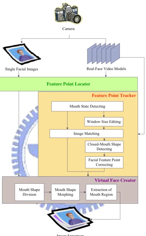
The virtual face creator we propose will then divide and morph the mouth shapes to get the bottom part of every virtual face. The final step is to extract the mouth region from the virtual face and integrate it with the input image. This completes the proposed process for virtual face creation.
20
Camera
Image Sequences
Single Facial Images Real-Face Video Models
Feature Point Locator
Virtual Face Creator
Feature Point Tracker
Mouth State Detecting
Window Size Editing Image Matching
Closed-Mouth Shape Detecting Facial Feature Point
Correcting Mouth Shape Division Mouth Shape Morphing Extraction of Mouth Region
21
Chapter 3
Tracking of Facial Feature Points
3.1 Idea of Proposed Techniques
As mentioned in Section 1.2.2, during tracking of facial feature points, suppose that a subimage w at coordinates (s, t) within an image f is processed. Then, the moving range of w inside f is taken to be [2s+1, 2t+1] in this study. The region of w is called a content window, and the moving range is called a search window. We propose in this study an image matching technique using the mouth movement information to change the size of the content window and the search window. Applying this technique, we can solve the interference problem of changed mouth-shape and teeth appearances mentioned in Section 2.1.
In this chapter, the necessity of changes of content and search window sizes and correction of facial feature point positions are explained in Section 3.1.1 and Section 3.1.2, respectively. Finally, the proposed method for tracking facial feature points is described in Section 3.1.3.
3.1.1 Necessity of Changes of Window Sizes
Because the mouth shapes are not all the same during a human’s talking process, the content window sometimes will include insufficient or too much information for image matching. Two other reasons for using different window sizes for each feature point are that the teeth will interfere the matching process in the tracking of some feature points and that the movement ranges of some feature points are different. So a
22
window size adaptation technique is proposed.
Examples of using the changed and unchanged window sizes are shown in Figure 3.1: Figures 3.1(a) and 3.1(b) are results of applying a constant window size, and Figures 3.1(c) and 3.1(d) are those of applying dynamically changed window sizes. We can find that by the former scheme the points are tracked erroneously to stay at the same position, as shown in Figure 3.1(b), and that by the latter scheme the points are tracked correctly to be at the edge of the mouth, as shown in Figure 3.1 (d).
(a) (b)
(c) (d) Figure 3.1 Examples of the changed and unchanged window sizes. (a) The 69th frame of a video using a
constant window size. (b) The 72th frame of a video using a constant window size. (c) The 69th frame of a video using dynamically changed window sizes. (d) The 72th frame of a video using dynamically changed window sizes.
3.1.2 Necessity of Corrections of Facial Feature Point
Positions
When a person in a video model says “a-u” as shown in Figure 3.2, we can find that the mouth is shrinking and the inner upper mouth part has more and more
23
wrinkles. Another finding is that the outer upper mouth part is brightening. One thing deserves to be mentioned is that the skin of the inner mouth part will be revealed so that the points of the inner upper mouth part looks like moving up, as shown in Figures 3.2(a) through 3.2(d).
Due to such changing image information, including the shape, brightness, and texture, the image matching is unreliable; therefore, we must correct the positions of feature points when the mouth of a video model has the shapes of “a” and “o.” A wrong matching result is shown in Figure 3.2(e) from which it is seen that after connecting the points, the mouth shape becomes an opened one, but it is in fact a closed mouth. After applying the proposed correction technique, the points of the inner mouth part are located on correct positions, as shown in Figure 3.2(f).
(a) (b) (c)
(d) (e) (f)
Figure 3.2 Facial feature point tracking result of mouth shape of a person saying “u.” (a) Tracking result of 34th frame of a video. (b) Tracking result of 37th frame of a video. (c) Tracking result of 40th frame of a video. (d) Tracking result of 43th frame of a video. (e) Connecting the points in the 43th frame of a video. (f) The 43th frame of a video after correction using proposed method.
24
3.1.3 Tracking Process
In the proposed method, we track the facial feature points in the frames using the
size changing information of a mouth, which is acquired from the difference between
the size of the mouth in the current frame and that of the previous frame. The changing information represents the mouth movements so that we can know the
mouth states. Then, we edit the size of the content window and the search window,
and correct the positions of the feature points according to the mouth states. The flowchart of the proposed feature point tracking process is shown in Figure 3.3.
25
3.2 Definition of Mouth States Using
Mouth Size Changing Information
We propose to use the facial animation parameter units MW0 and MH0, which are the width and the height of a mouth, to represent mouth movements, as shown in Figure 3.4. First, we define some mouth states to indicate how the mouth moves. We only care about some frames, in which, the size of the mouth is different from that of the previous frame. These frames are called changed frames.
The width difference wDiff of the mouth of the current frame from that of the previous frame, and the height difference hDiff of the mouth of the two frames, are used to represent the changed size of the mouth. Two states we define for use in the proposed technique are: opening state and closing state, and they are described in the following.
MW0
MH0
Figure 3.4 The FAPUs in the proposed system.
3.2.1 Mouth states
The opening state represents that a mouth is opening. The criteria for judging an opening state are that hDiff of the current changed frame is larger than zero, and that
hDiff of the previous changed frame or wDiff of the current frame is larger than zero.
26
closing state are that one of wDiff and hDiff of frames, including the current changed frame and the previous changed frame, is smaller than zero.
According to these criteria, we can label states to every frame. A line chart for illustrating this is shown as Figure 3.5, where the 32th through 46th frames are assigned the closing state.
For example, if the 32th frame is the currently-processed frame and if we compare the values wDiff of the 31th frame and the 32th one, then according to the previously-mentioned criteria the 32th frame is assigned the closing state.
Figure 3.5 Aline chart of the frames of the closing state from the 32th through the 46th frames of the
video model.
3.2.2 Detection of Mouth states
We compare wDiff and hDiff of the current frame with those of the last changed frame which are denoted as pre_wDiff and pre_hDiff. In other words, wDiff, hDiff,
pre_wDiff, and pre_hDiff are the mouth size changing information.
Based on the previously-mentioned criteria, the detail of the proposed technique for mouth state detection is described in the following algorithm.
27
Algorithm 3.1. Detecting the mouth states using mouth size changing information.
Input: A video model Vmodel and locations Lfp of the feature points of the first frame of
Vmodel.
Output: The mouth states S of every frame.
Steps:
1. For every frame Fcurrent of Vmodel, perform the following steps with the initial value of S set none.
1.1 For points 8.4, 8.9, 8.3, and 8.2, apply an image matching technique to extract their corresponding points of Fcurrent using Lfp, and then update Lfp according to the locations of these extracted points of Fcurrent.
1.2 Compute MW0 and MH0 of Fcurrent in the following way:
MW0 = 8.3.x – 8.4.x; MH0 = 8.2.y – 8.9.y.
Then, denote MW0 and MH0 of Fprevious as MW0′ and MW0′.
1.3 Calculate the difference of the mouth size between frames Fprevious and Fcurrent by the following way:
wDiff = MW0 − MW0′; hDiff = MH0 − MH0′.
2. Assign a mouth state to S by comparing wDiff, hDiff, pre_wDiff, and pre_hDiff in the following way:
if wDiff = 0 and hDiff = 0, then S is unchanged;
if wDiff > 0 and hDiff > 0, then set S = Opening state;
if hDiff > 0 and pre_hDiff > 0, then set S = Opening state;
if wDiff < 0 and pre_wDiff < 0, then set S = Closing state;
if hDiff < 0 and pre_hDiff < 0, then set S = Closing state.
28
not equal to 0.
For example, if wDiff and pre_wDiff are both larger than zero, it means that the mouth is opening horizontally.
3.3 Image Matching Using Correlation
Coefficients Using Dynamically
Changed Window Size
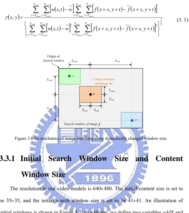
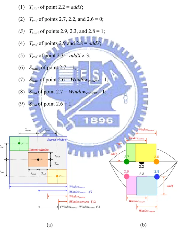
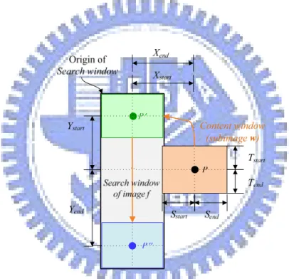
The details of using dynamically changed window sizes are described in this section. The origin P of the content window is set at the center of the window, and the origin of the search window is at the left top. The distances from P to the four borders of the content window are taken to be [Sstart, Send, Tstart, Tend], as shown in Figure 3.6. The content widow moves around and inside the search window of image f. The range the content window can move is taken to be [Xstart+Xend, Ystart+Yend]. The center of the search window has the same coordinates as those of P.
We propose to edit the distance values, including Sstart, Send, Tstart, Tend, Xstart, Xend,
Ystart, and Yend, to achieve the goal of changing sizes of the content window and search window.
After changing these distance values, we can use them as parameters to the previously-mentioned image matching technique in Section 1.2.2. We compute a value of γ each time the content window moves one pixel, so we have to compute (Xstart+Xend) × (Ystart+Yend) times in a session of content search. And Equation (1.1) can be written as follows:
29
( )
[
( )
]
[
(
) (
)
]
( )
[
]
[
(
) (
)
]
2 1 2 2 , , , , , , , ⎭ ⎬ ⎫ ⎩ ⎨ ⎧ + + − + + − + + − + + − =∑ ∑
∑ ∑
∑ ∑
∑ ∑
= = = = = = = = end start end start end start end start end start end start end start end start S S s T T t S S s T T t S S s T T t S S s T T t t y s x f t y s x f w t s w t y s x f t y s x f w t s w y x γ . (3.1)Figure 3.6 An mechanics of image matching using dynamically changed window size.
3.3.1 Initial Search Window Size and Content
Window Size
The resolution in our video models is 640×480. The initial content size is set to be 35×35, and the initial search window size is set to be 41×41. An illustration of initial windows is shown in Figure 3.7. In addition, we define two variables addX and
addY by the points 2.2 and 8.1 of the first frame of the video model, which can be
added with or assigned to the distance values. More specifically, we assign the initial distance values, the value of addY, and that of addX in the following way:
(1) Windowsearch= the width of the search window; (2) Windowcontent= the width of the content window; (3) Sstart, Send, Tstart, and Tend = (Windowcontent − 1) / 2; (4) Xstart, Xend, Ystart, and Yend = (Windowsearch −1) / 2;
30
(5) addX = Upper lip H = 2.2.y − 8.1.y; (6) addY= addX × 2.
And we specify the initial values of the distance values of the inner-mouth feature points by the following way:
(1) Tstart of point 2.2 = addY;
(2) Tend of points 2.7, 2.2, and 2.6 = 0;
(3) Tstart of points 2.9, 2.3, and 2.8 = 1; (4) Tend of points 2.9 and 2.8 = addY; (5) Tend of point 2.3 = addX × 3; (6) Sstart, of point 2.7 = 1;
(7) Sstart of point 2.6 = Windowcontent – 1; (8) Send of point 2.7 = Windowcontent – 1; (9) Send of point 2.6 = 1. P Tstart Tend Send Sstart Xstart Ystart Xend Yend Search window P P Windowcontent Windowsearch Content window (WindowSearch-1)/2 (Windowcontent -1)/2
(Windowsearch- Windowcontent)/ 2
2.9 2.2 8.1 2.7 2.6 2.8 addY Windowcontent Windowcontent Windowcontent Windowcontent addY 2.3 (a) (b)
Figure 3.7 An illustration of initial window size. (a) Initial search window size. (b) Initial content window size.
31
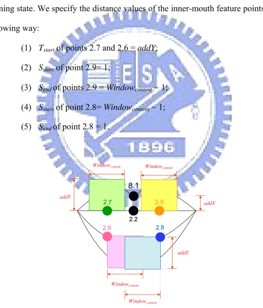
3.3.2 Content Window Size of Opening State
In an opening state, we wish the inner upper mouth part to contain more corner information, so we enlarge the height of their content windows. And we hope the inner bottom mouth to contain more lip information, so we move their content windows to the center mouth and move the center P to the edge of the content windows, as shown in Figure 3.8. Because the input facial image is a neutral facial image with a closed mouth which is going to open, the initial state is set to the opening state. We specify the distance values of the inner-mouth feature points by the following way:
(1) Tstart of points 2.7 and 2.6 = addY; (2) Sstart of point 2.9= 1;
(3) Send of points 2.9 = Windowcontent − 1; (4) Sstart of point 2.8= Windowcontent − 1; (5) Send of point 2.8 = 1.
32
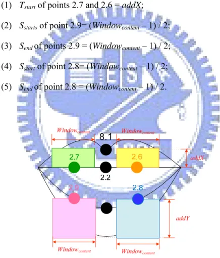
3.3.3 Content Window Size of Closing State
In a closing state, the desire content window size is opposite to that for an opening state. We wish the inner mouth to contain less skin information, so we reduce the height of the content window of the inner upper mouth part and move the content window of the inner bottom mouth part back to the initial position, as shown in Figure 3.9. We specify the distance values of the inner-mouth feature points by the following way:
(1) Tstart of points 2.7 and 2.6 = addX;
(2) Sstart, of point 2.9= (Windowcontent – 1) / 2; (3) Send of points 2.9 = (Windowcontent – 1) / 2; (4) Sstart of point 2.8= (Windowcontent – 1) / 2; (5) Send of point 2.8 = (Windowcontent – 1) / 2.
Figure 3.9 An illustration of content window size of closing state.
3.3.4 Balancing Feature Point Position by Changing
Search Window Size
33
video models. If we do not adjust the positions, the virtual face creation will create a virtual face with a crooked mouth, according to our experimental experience. We propose in this study an adaptive image matching technique to make feature point locations to be symmetric in position.
We wish the content window to move only in a vertical way, as shown in Figure 3.10, with the vertical move range being from P′ to P′′. In order to move vertically, we set the distance values of Xend equal to that of Xstart so that the width of the search window is equal to the width of the content window.
Figure 3.10 Illustration of balancing feature point positions by changing search window size.
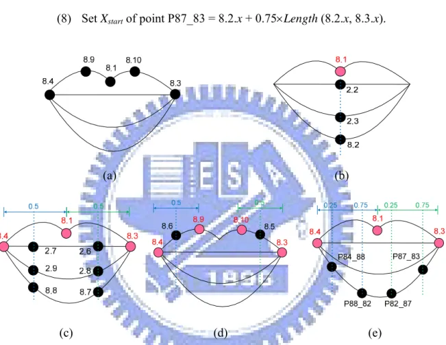
First, we extract the positions of points 8.4, 8.9, 8.1, 8.10, and 8.3, as shown in Figure 3.11(a). And set the Xstart of points 2.2, 2.3, and 8.2 to be 8.1.x, as shown in Figure 3.11(b). Second, we set the Xstart of other points in the following way, as shown in Figure 3.11(c) through Figure 3.11(e).
(1) Set Xstart of points 2.7, 2.9, and 8.8 = Average (8.4.x, 8.1.x); (2) Set Xstart of points 2.6, 2.8, and 8.7 = Average (8.1.x, 8.3.x);
34
(3) Set Xstart of point 8.6 = Average (8.4.x, 8.9.x); (4) Set Xstart of point 8.5 = Average (8.10.x, 8.3.x);
(5) Set Xstart of point P84_88 = 8.4.x + 0.25×Length (8.4.x, 8.2.x); (6) Set Xstart of point P88_82 = 8.4.x + 0.75×Length (8.4.x, 8.2.x); (7) Set Xstart of point P82_87 = 8.2.x + 0.25×Length (8.2.x, 8.3.x); (8) Set Xstart of point P87_83 = 8.2.x + 0.75×Length (8.2.x, 8.3.x).
(a) (b)
(c) (d) (e)
Figure 3.11 A illustration of setting the value of Xstart and Xend.
3.4 Detection of Closed-Mouth Shapes
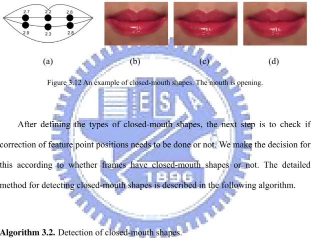
We detect closed-mouth shapes to correct the feature point positions. Although the mouth seems to be unchanged while the mouth is opening, in fact their shapes in the frames are different from one another, as shown in Figures 3.12(b) through
35
3.12(d). When a mouth is nearly closed, point 2.7 is closed to point 2.9, and point 2.6 is closed to point 2.8, so are points 2.2 and 2.3, as shown in Figure 3.12(a). At this time, it needs to the correct the feature point positions.
In this study, we define three types of closed-mouth shapes, which will be described in Sections 3.4.1, 3.4.2, and 3.4.3.
(a) (b) (c) (d)
Figure 3.12 An example of closed-mouth shapes. The mouth is opening.
After defining the types of closed-mouth shapes, the next step is to check if correction of feature point positions needs to be done or not. We make the decision for this according to whether frames have closed-mouth shapes or not. The detailed method for detecting closed-mouth shapes is described in the following algorithm.
Algorithm 3.2. Detection of closed-mouth shapes.
Input: A frame F of a video model Vmodel.
Output: A Boolean set Smouth{S1, S2, S3} of the frame F, with Si describing the type of
the detected mouth shape .
Steps:
1. Compute the heights h1, h2, and h3 of inner mouth by:
h1 = abs (2.7.y − 2.9.y);
36
h3 = abs (2.2.y − 2.3.y).
2. Set S1, S2 and S3 in the following way:
⎩ ⎨ ⎧ ≤ = otherwise , if h S , 0 1 1 1 1 ; (3.2) ⎩ ⎨ ⎧ ≤ = otherwise , if h S , 0 1 1 2 2 ; (3.3) ⎩ ⎨ ⎧ ≤ = otherwise , if h S , 0 1 1 3 3 , (3.4)
where Si labeled 1 corresponds to type-i closed-mouth shape. If S1, S2 and S3 are all labeled 0, it represents that the mouth does not have a closed-mouth shape.
3.4.1 Type-1 Closed-Mouth Shape
When the distance of points 2.7.y and 2.9.y is smaller than one, we call this mouth shape as type-1 closed-mouth shape, as illustrated by Figure 3.13.
(a) (b)
Figure 3.13 Diagrams of type-1 closed-mouth shape. (a) The left points of inner mouth. (b) An example of type-1 closed-mouth shape.
3.4.2 Type-2 Closed-Mouth Shape
When the distance of points 2.6.y and 2.8.y is smaller than one, we call this
2.7
2.9
37
mouth shape as type-2 closed-mouth shape, as illustrated by Figure 3.14.
2.6
2.8
(a) (b)
Figure 3.14 Diagrams of type-2 closed-mouth shape. (a) The right points of inner mouth. (b) An example of type-2 closed-mouth shape.
3.4.3 Type-3 Closed-Mouth Shape
When the distance of points 2.2.y and 2.3.y is smaller than one, we call this mouth shape as type-3 closed-mouth shape, as illustrated by Figure 3.15.
(a) (b)
Figure 3.15 Diagrams of type-3 closed-mouth shape. (a) The middle points of inner mouth. (b) An example of type-3 closed-mouth shape.
3.5 Correction of Feature Point
2.2
2.3
2.6
2.8
38
Locations of Closed Mouth
Before correction of the locations of the feature points of the closed mouth, we describe the idea of such correction in the green channel in Section 3.5.1. Then we describe how we extract mouth information by edge detection and bi-level thresholding in the green channel in Section 3.5.2. Finally, the proposed correction process is described in Section 3.5.3.
3.5.1 Idea of Correction in Green Channel
Because the green values of the pixels of a mouth are much smaller than those of the facial skin, as shown in Figure 3.16, it is easy to distinguish the mouth from the facial skin and the teeth. We therefore propose using the green channel to extract the mouth information.
(a) (b) (c)
Figure 3.16 The RGB channel images of partial part of 15th frame of a video model. (a) Red-channel
image. (b) Green-channel image. (c) Blue-channel image.
3.5.2 Edge Detection and Bi-level Thresholding in
Green Channel
The proposed system performs edge detection to check if the mouth has a closed-mouth shape, as described in the following algorithm.
39
thresholding in green channel.
Input: A frame F of a video model Vmodel and a threshold value t for edge value
thresholding.
Output: A binary image B.
Steps:
1. Take the green-channel image G of F and let G(x, y) denote the green value at pixel (x, y).
2. Detect edges in G by applying the following sobel operator, as shown in Figure 3.17, to implement Equation (3.5) below to get an edge image Bedge:
(
)
(
) (
)
(
) (
)
7 8 9 1 2 3 3 6 9 1 4 7 , 2 2 2 2 , S x y z z z z z z z z z z z z = + + − + + + + + − + + (3.5)where z5 denotes G(x, y), z1 denotes G(x − 1, y − 1), and so on.
3. Threshold Bedge with t as the threshold value to get a binary image B(x, y) by the following equation: ⎩ ⎨ ⎧ ≤ > = , ) , ( , 0 ; ) , ( , 1 ) , ( t y x I if t y x I if y x B (3.6)
where t is a user defined constant (t = 100 in this study).
After the execution of the above algorithm, pixels of B(x, y) labeled 1 correspond to edge pixels.
-1 -2 -1 -1 0 1
0 0 0 -2 0 2
1 2 1 -1 0 1
40
3.5.3 Correction Process
The final step in feature point tracking is to correct feature points in frames which have closed-mouth shapes. The detail of the correction process is described in Algorithm 3.4 below.
Algorithm 3.4. Correction of feature point positions.
Input: A binary image B generated by Step 1 of Algorithm 3.3, the positions of the
feature points of B, and three Boolean values S1, S2, and S3 generated by Algorithm 3.2.
Output: Feature points with correct positions and three Boolean values S1, S2, and S3.
Steps:
1. Let white_pixels(p1, p2) denote the function for counting the number of white pixels along the line of two points p1 and p2.
2. If S1 = true or S2 = true, perform the following steps.
2.1 If white_pixels(2.7.y, 2.9.y) = 0 or white_pixels(2.6.y, 2.8.y) = 0, adjust the coordinates of points by the following way:
2.1.1 point 2.7.y = point 2.9.y; 2.1.2 point 2.6.y = point 2.9.y; 2.1.3 point 2.8.y = point 2.9.y.
2.2 Otherwise, set S1 = false and S2 = false. 3. If S3 = true, perform the following steps.
3.1 If white_pixels(2.2.y, 2.3.y) = 0, adjust the coordinates of points by the following way:
3.1.1 point 2.2.y = Average(2.2.y, 2.3.y); 3.1.2 point 2.3.y = Average(2.2.y, 2.3.y). 3.2 Otherwise, set S3 = false.
41
3.6 Experimental Results
Some experimental results of applying the proposed method for tracking feature points are shown in Figure 3.18, from which it can be seen that the proposed method not only can track facial feature points, but also can correct the positions of the feature points so that we can get the correct results.
(a) (b) (c)
(d) (e) (f)
(g) (h) (i)
Figure 3.18 A resulting sequence of tracking feature points in a video clip of speaking “everybody” in Chinese.
42
Chapter 4
Creation of Virtual Faces with
Dynamic Mouth Movements
4.1 Idea of Proposed Technique
The main purpose of this study is to enable a person seen in a still input image to say the same words uttered by another person appearing in a video model, that is, to let the input image have the same mouth shapes as those in the video model. In this study, we use a morphing method to warp the input image to the frames in the video model to achieve this goal. That is, we divide mouth shapes into quadrilaterals in the input image and do the same in every frame of the video model, and then map every quadrilateral of the input frame to those of the frames of the video model.
In this chapter, the mouth shape division technique we propose is described in Section 4.1.1, and the main steps of the proposed virtual face creation process are described in Section 4.1.2.
4.1.1 Mouth Shape Division
We separate the mouth image into two parts: a mouth part and a skin part which is near the mouth. The mouth part is divided into fourteen overlapping quadrilaterals, and the skin part is divided into thirteen overlapping quadrilaterals, as shown in Figure 4.1.