Holographic data storage with a planar-integrated optical
write-read head
Matthias S¨
ollner
a, Udo Vieth
a, Ken Yuh Hsu
b, Shiuan Huei Lin
b, Matthias Gruber*
a aOptical Microsystems Group, University of Hagen,
Universit¨
atsstr. 27, 58097 Hagen, Germany
b
Dept. of Electrophysics, National Chiao Tung University,
1001 Ta Hsueh Rd., Hsinchu, Taiwan
ABSTRACT
The construction of a write-once-read-many-type optical write-read-head for volume holographic data storage in disk-based photopolymer storage media is discussed. Its design is based on the photonic integration concept called planar-integrated free-space optics. A proof-of-principle demonstrator was fabricated, it contains a 3mm thick fused silica wafer that carries most passive components for the reference and the signal beam relay in the form of diffractive optical elements, a translucent liquid crystal microdisplay, and the CCD sensor of a webcam. Phenanthrenequinone-doped polymethylmethacrylate was chosen as storage material, a DPSS laser withλ = 532nm serves as light source. We report about preliminary experiments to determine suitable exposure parameters for holographic write-read operations, and on the use of data matrix codes for the encoding and decoding of information.
Keywords: holography, data storage, PIFSO, planar micro-optics, integration, photopolymer, PQ:PMMA
1. INTRODUCTION
More and more computer applications nowadays are dealing with huge amounts of data such as video sequences. Thus the needed capacity in data storage is still growing. In recent years volume holographic data storage has been drawn in consideration again1although this was not the primary application of holography for many years. The new interest is due to the need of more capacity and the prospect of new materials which don’t need chemical processing for development. But also the possibility of writing complete data pages (e.g. videoframes) in only one write cycle gives volume holographic data storage a big chance in the future market of storage devices.
We consider the use of planar design and fabrication technologies for the construction of a micro-integrated write-once-read-many-type (WORM-type) volume holographic memory. The system concept can be regarded as an upgrade of a conventional CD-ROM system in the sense that standard optical disks are replaced by disks with a photopolymer layer for volume holographic data storage and that the conventional pickup head is replaced by a compact module that can perform Fourier holographic writing and reading operations. We have designed a proof-of-principle demonstrator of this storage concept and report about progress of the experimental setup as well as about achieved preliminary experimental results.
2. PLANAR-INTEGRATED SYSTEM DESIGN
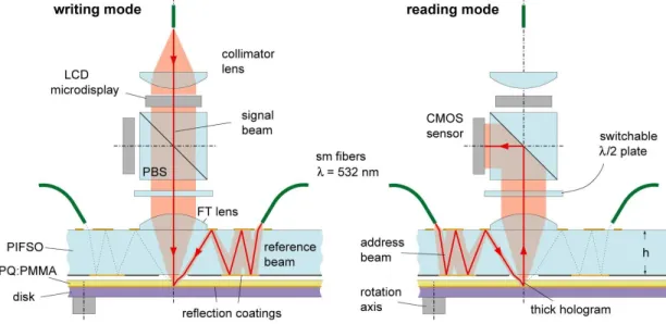
The architecture of the holographic write-read head follows the design principle of planar-integrated free-space optics (PIFSO), which means that an optical system is folded into a transparent wafer in such a way that optical signals propagate along zig-zag paths between the wafer surfaces and that beam manipulations are carried out by (reflective, refractive, and/or diffractive) optical components that are integrated into these surfaces and fabricated by means of planar technologies.2 The PIFSO approach permits a coplanar positioning of the w/r head and the storage disk at close distance and it provides high mechanical stability, which is important for holographic setups. The w/r head is designed to relay the signal beam and to generate two counter-propagating reference beams. The signal beam is coupled into and out of the storage disk in surface-normal direction, the
eldsrlotiwa eIslq \A ri msigolorl ,hirlj 9bom nibsei 20M0 ioensa aeeibbs ms9d aisdi ma mn = ebom nithw 9Ofl9199l m sed ioJsmiIIoo anel aQnifsoo noiloelte, ciaj yslqaibo,oim AM M: Dci 1aib
reference beam paths are inclined by about 30 degrees and symmetric with respect to the axis of the signal beam. The idea is to use one of them during the holographic recording and the other one for the read out; due to its counter-propagating nature it will be diffracted from the hologram as phase-conjugate version of the signal beam, which propagates in opposite direction of the original signal beam allowing us to address the holographic disk from one side only. As holographic storage material phenanthrenequinone-doped polymethylmethacrylate (PQ:PMMA) is used.
Figure 1. Design concept of a compact planar-integrated optical write-read head
3. RECORDING MATERIAL PQ:PMMA
The recording material has been developed at the National Chiao Tung University, Taiwan. It is based on polymethymethacrylate (PMMA) and doped with phenanthrenequione (PQ) molecules, which are photosensitive. The dopant PQ is embedded in a rigid PMMA matrix which almost eliminates the problem of material shrinkage during and after exposure. The material was also optimized for sensitivity and dynamic range. Light exposure starts a photochemical reaction and leads directly to a change of the refractive index. So it is capable of storing interference patterns and is useful for write-once and read-multiple holographic data storage. While recording the free PQ molecules get excited by incoming photons. So the PQ molecules can react with the MMA molecules and form a one to one attachment. This results in a change of the refractive index and a change in colour. The unexposed material has a yellowish colour. After exposing to light the material turns fully transparent (Fig. 2a) when all PQ molecules are used.3, 4 The material is optimized for 514nm but is also sensitive to 532nm, but sensitivity is significantly lower. Therefore we tested if recording of holograms is possible with 532nm.
4. RECORDING HOLOGRAMS ON PQ:PMMA
Some experiments in recording holograms on this material have also been done recently in our laboratory. First we recorded a grating by crossing two laser beams in the plane of the recording material. The produced grating was acting as a beam splitter when lit with the reference beam only. After this first test, setup was changed to record a hologram of a two-dimensional black and white image (Fig. 3a). The image has been printed on a transparent foil with a laser printer. In the final setup this foil is replaced by a translucent LCD (liquid crystal display), which will spatially modulate the object beam with digital data. Afterwards the recorded hologram has been reconstructed by lighting the hologram with the reference beam only. The reconstructed and projected image can be seen in Fig. 3b. In the final demonstrator the reconstructed image will be recorded by a CCD-camera to decode the digital data out of the captured two-dimensional image. This first tests proofed that recording holograms on PQ:PMMA with 532nm and the available DPSS laser is possible. With an incoming
LNWIV
CH
HC=I.
OCH
bIAiII'JV C..OCH3
H1'.0
CH2
bO
9tfl9ifbfb1
. Iii isIili9Vi41Lifl1& (a) (b)Figure 2. (a) Phenanthrenequinone-doped polymethylmethacrylate (PQ:PMMA) exposed toλ = 532nm, (b) Chemical structure of phenanthrenequinone (PQ), methylmethacrylate (MMA) and polymethylmethacrylate (PMMA)
power of about Pref+obj = 10mW at the hologram plane after about 15 seconds an interference pattern was recorded and a reconstruction of the image was possible.
5. MICRO-OPTICAL SYSTEM FOR LEADING REFERENCE BEAMS
As next step the designed micro-optical system has been manufactured in our cleanroom in Hagen. The created PIFSO system consists of multilevel surface-relief diffractive lenses that were fabricated on a 3mm thick fused silica wafer by means of binary lithography and reactive ion etching, reflective components were covered with a thin layer of aluminium by thermal vapour deposition. We tested the system for it’s main purpose. We could see that it is possible to relay the two reference beams through the micro-optical system as expected. We could also show, that it is possible to generate a counter-propagating beam for reconstruction of the hologram. The system is then integrated in the demonstrator setup. In figure 4a the PIFSO and the path of one reference beam is shown. One can see clearly the lenses on top of the substrate (round shapes) and the mirror on the bottom (rectangular shape). The beam comes from the right side, couples into the substrate, propagates through the system to the left side, where it leaves the PIFSO at the bottom. Figure 4b shows the experimental setup for testing the optical micro-system.
(a) (b)
211P24L9G nsq 2!I!C9
I
psui b9p LGGLGUCG (a) (b)Figure 4. (a) manufactured PIFSO (b) experimental setup for testing the PIFSO
6. EXPERIMENTAL SETUP
We have setup a demonstrator for holographic recording with the manufactured PIFSO system. The demon-strator consists of two parts: the optical system (Fig. 5a) and the control system (Fig. 6).
The optical system is designed for leading the object beam and two reference beams to the micro-optical system. We split the incoming beam in object and reference part. In the object beam a translucent liquid crystal display (LCD) is used to modulate the beam spatially. This LCD is illuminated with a spread up and collimated beam to achieve equal brightness over the whole display. Behind the display it is focused to the recording area in the hologram plane. While reading the hologram the same path is used in the other direction. A cubic beam splitter is used to lead the reconstructed image on the CCD-sensor of a webcam. The micro-display, and the CCD-camera are integrated into the setup for data I/O and control purposes, they build the connection between optical and electronical components. The optical power is provided by a DPSS laser with a wavelength of 532 nm and delivered to the w/r head via single-mode optical fibers. The two reference beams are coupled into the fibers which guide the light directly to the entry point of the PIFSO-system. I picture of the setup is shown in figure 5b.
For controlling the system a self-developed windows-based software package is used. The software is used for coding, presenting, capturing and decoding data. Entered text is coded into a two-dimensional image. This
(a) (b)
image is shown on the translucent mini-LCD for recording the hologram. While reading a hologram the image is captured with a CCD-camera connected through USB. Afterwards the software tries to decode the data from the image back to readable text. For coding and decoding images we use algorithms from the open source project libdmtx .5 This is a open source library for generating and decoding data matrix codes (some type of two-dimensional barcode) which are commonly used in industrial projects, e.g. for tracking goods and similar applications. The software is also capable of controlling four shutters over a microcontroller board. These shutters are used for switching beams computer controlled. So we can choose reading or writing mode and control exposure time through the software. The hardware components of the control system can be seen in figure 6. The mini-LCD is attached to the PC over a USB-VGA-converter and a VGA-PAL-converter as the electronics of the LCD expects a PAL-signal. The CCD-camera is connected to the USB-Port, the shutters are controlled via RS-232 serial communication.
USB-VGA-Converter USB PC USB PAL VGA VGA-PAL-Converter Display-Electronics Mini-LC-Display USB-Webcam with CCD-Chip RS-232 Shutter Microcontroller-Board LCD with Data-Matrix-Code PIC 16F628 RS-232 Interface Microcontroller
Figure 6. Experimental setup - control system
7. FURTHER STEPS
In the near future the demonstrator setup will be tested for disk-based holographic storage media. Writing and reading of holograms should be possible. Furthermore we plan to increase the integration of the components and to integrate the light source in the compact write-read head.
REFERENCES
[1] Sarid, D. and Schechtman, B. H., “A roadmap for optical data storage applications,” OPN , 32–37 (May 2007).
[2] Vieth, U., Gruber, M., Hsu, K.-Y., and Lin, S.-H., “Integrated micro-optical write-read head for holographic data storage,” Proc. DGaO (2007).
[3] Lin, S. H., Lin, J.-H., Chen, P.-L., Shiao, Y.-N., and Hsu, K. Y., “Doped poly(methyl methacrylate) pho-topolymers for holographic data storage,” Journal of Nonlinear Optical Physics & Materials 15, 239–252 (May 2006).
[4] Hsu, K. Y., Lin, S. H., Hsiao, Y.-N., and Whang, W. T., “Experimental characterization of phenanthrenequinone-doped poly(methyl methacrylate) photopolymer for volume holographic storage,”
Op-tical Engineering 42, 1390–1396 (May 2003).
[5] Laughton, M. et al., “libdmtx open source data matrix software.” Website (2009). Available online at http://www.libdmtx.org/ visited in January 2009.