分散式智慧型汽車網路監控系統的設計與實作(II)(期末報告)
Distributed Network Monitoring and Control for Intelligent Automobile: Design and Implementation (II) 計劃編號:NSC 96-2221-E-009-198
執行期限:96 年 8 月 1 日至 97 年 7 月 31 日 主持人:王啓旭 職稱:教授
執行機構:國立交通大學
Abstract
In this report, an advanced vehicle Network is explored. This network include CAN bus as the Powertrain bus and the MOST optical bus to connect the media devices, and another simple low speed I-bus to connect all the dashboard instrument devices. Then there are three different network buses in an automobile. This MOST optical network is mainly used to improve the performance of the multimedia devices in an intelligent automobile. We also demonstrate a carbon copy of this network outside the automobile.
1. Introdcution
The CAN (Controller Area Network) is a serial communications protocol which supports distributed realtime control with a very high level of security (Multi-master hierarchy, Broadcast communication, Error detecting and re-transmission). Its main features are:
- Message-oriented transmission protocol. - Message contains the priority of the message.
- Easy to add a receiver station to an existing CAN network. In this report , we will go over CAN protocol first, and combine MOST Network which we study in the first year. Combine these two networks together, and build up an advanced vehicle network.
2. The CAN Bus
z Traditional point-to-point Topology
Figure 1 CAN Bus Topology
Figure 2 CAN Protocol
Principles of data exchange
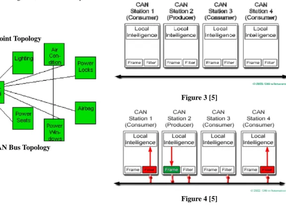
Each node link in CAN bus can broadcast messages. Messages define is a very important job in CAN Messages Map should highlight the relationship between each message and devices in CAN.
Devices can reject messages which doesn’t belong to them. For example: station 3 reject message from bus but station 1&4 accepts.
Figure 3 [5]
z CAN Protocol
Real-time data Arbitration
Figure 5
Figure 6
Types and Roles of CAN Frames Data Frame
This frame sends data from the transmit unit to the receive unit.
Figure 7
SOF Start of frame ID Arbitration field Control Control field Data Data field CRC CRC field ACK ACK field EOF End of frame
Format of CAN protocol Frame Data Frame Data Frame
This frame sends data from the transmit unit to the receive unit
Figure 8
Format of CAN protocol Frame Overload Frame
Overload Frame
Figure 9
Points of CAN Communication Arbitration #1 What is arbitration?
It means that when two or more units start transmitting at the same time , the arbitration fields of data are compared bitwise to determine which message has priority.
Mechanism Of arbitration
In CAN communication, the unit that has started transmitting first during a bus idle state gains the right to transmit . If two or more units start sending at the same time , they are arbitrated for contention by comparing their arbitration fields bitwise and the unit that has more dominant bits than other units gains the right to transmit.
Points of CAN Communication Arbitration #2
Figure 10 Arbitrated range of filed
CAN Communication Hardware
Synchronization
Synchronization in CAN communication has 2 methods. In CAN communication, the timing of operation between each unit is sure to delay because there is a clock error or a bus delay, so each unit has to synchronize timing of operation respectively.
Hardware synchronization
When a recessive to dominant edge is detected while the bus remains idle, each unit adjusts the timing to the edge as beginning of a message and starts transmitting or receiving.
Figure 11
Points of CAN Communication
Resynchronization Resynchronization
A mistimed operation between each unit that may occur during transmission or reception is resynchronized.
Figure 12
Figure 13
Points of CAN Communication Error detection
Type of Errors
Bit error This error is detected when the output level of any bit and its level on the bus do not match. Stuff error This error is detected when the same level is
detected for six consecutive bits in the bit-stuffing field.
CRC error This error is detected when the received CRC sequence differs from the result of CRC that is calculated from the received data.
Form error This error is detected when affixed-form bit field (CRC delimiter, ACK delimiter, EOF field) contains one or more illegal bits.
ACK error This error is detected when a transmit unit detected recessive bits in the ACK slot.
Timing Chart of CAN Communication #1
When transmission or reception has finished successfully.
Figure 14
Timing Chart of CAN Communication #2 When an error frame was transmitted due to an ACK error detection and transmission or reception has finished successfully after re-transmitting.
Figure 15
3 Multimedia Applications using MOST
Hardware Overview
Figure 16 MOST Devices assembled for our applications
This section provides an overview of the MOST devices assembled for our applications; moreover, Figure 16 depicts how the devices are connected via Plastic Optical Fibers (POF) in a ring topology. Manufactured by OASIS SiliconSystems (which is now part of SMSC), the rapid prototyping devices provide a convenient way to test and demonstrate multimedia applications under MOST network. In addition to that, the MOST PCI Board and Optolyzer Interface Box are also useful to our applications.
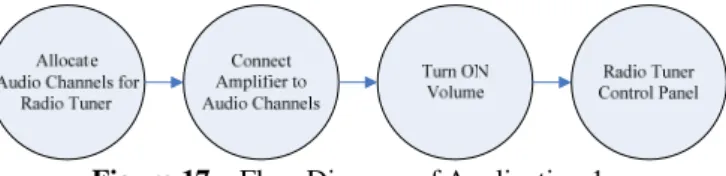
Application 1: Listen to the Radio
Source: RadioTuner4MOST Sink: Amplifier4MOST
Figure 17 Flow Diagram of Application 1
Application 2: Watch DVD movies
Source: DVDPlayer4MOST Sink: Amplifier4MOST
Listen to an audio CD on the MOST network. ‧
Watch VCD/DVD movie
‧ s.
(Video is output from the DVD player while audio is output from the amplifier.)
Figure 18 Flow Diagram of Application 2
4 Design and Implementation of Advanced Vehicle Control with CAN and MOST Networks
The experiment plant can be divided into three parts: P-bus (Powertrain bus), I-bus (Instrument bus), and O-bus (Optical bus).
Figure 19
The data link connector can access both the P-bus and the I-bus. With an adapter, Tech2 can be connected to the data link connector and can communicate with the different control modules on the P-bus and I-bus. Diagnostic communication with the control modules on the O-bus occurs
sure that information available on the I-bus and P-bus is available on the O-bus, and vice versa.
A bus is the leads over which information is sent digitally and serially. Digital means that the signal is either 1 or 0. Serial means that the information is sent in "packages" in close succession.
All the control modules in the car are connected via three buses. Two of these buses are electrical while the third is optical.
The two electrical buses are the P-bus (Powertrain bus) and I-bus (Instrument bus). The P-bus has two leads and the I-bus one lead. The difference in voltage between the two leads (P-bus) or the lead and ground (I-bus) is either 0 V or roughly 5 V. The information is coded so that different combinations of pulses, with the values 0 V and 5 V, have different meanings.
The optic bus is known as the O-bus and has an extremely high capacity. It is primarily used to send audio signals, e.g. from the radio receiver or CD changer to the amplifiers. Digital information is transmitted in a plastic cable by pulsating the sound at low and high intensities to thereby form 1s and 0s.
The experiment plant is shown in the following figures.
Figure 20
4-1. P-bus and I-bus
The two electrical buses are connected to the Column Integration Module (CIM), Infotainment Control Module (ICM) and data link connector. The buses are electrically
information is transferred between the O-bus and the electrical buses.
The P-bus has a data transfer rate of 500 kbits/s and the I-bus of 33 kbits/s. The data rate on the P-bus is high to allow the powertrain systems access to information with the shortest possible delay, for example during air mass compensation when the selector lever is moved from N to D or TCS or ESP modulation.
The control modules send out information on the bus whenever the information changes. As a safety precaution, the information is also sent at regular intervals irrespective of whether or not it is new.
The time between two transmissions depends on the information being transmitted and varies between 10 milliseconds (engine torque) and 10 second (VIN). When a control module sends information, the other control modules listen regardless of whether or not they use the information. A bus system means that it is sufficient with one sensor for each measurement function in the car.
The number of separate signal leads can also be reduced. For example, the engine management system has a coolant temperature sensor, which means that coolant temperature is always available to all systems. Therefore, the car only needs one coolant temperature sensor. Coolant temperature is used by the main instrument unit to control the temperature gauge, and the ACC to control ventilation fan speed and air distribution when starting from cold.
4-2 O-bus
The LEDs in the transmitters, though not laser diodes, produce high-intensity light. The light is therefore classed as laser class 1. Do not look directly at the light source (detached fiber of connection). Visual inspection to establish that light is emitted from a fiber is used during fault diagnosis. In such cases, do not point the fiber towards the eyes but shine the light onto a piece of paper or other light object and look at the reflection.
The optical bus consists of an orange 2.3 mm thick plastic cable that looks similar to a standard electrical cable. The optical cable contains a 1.0 mm diameter, transparent, plastic, optical fiber and two protective plastic layers. Each end of the cable has a plastic or brass cable terminal. The purpose of the terminal is to secure and centre the cable on the control module. Each control module is connected to two cables; one for incoming data and one for outgoing data. The bus is a ring bus, which means that messages are sent around the ring by the various control modules.
The messages are digital and consist of red light pulses. Each control module converts received messages from optical signals into electrical signals and then back into optical signals for transmission to the next control module.
The control module that is the source of a specific type of information modifies the information as necessary each time it passes. The other control modules are free to receive and use any relevant messages.
The O-bus has a data rate of 25 Mbit/s. This large capacity means that audio data can be sent in real-time
between a playback device or radio receiver and the amplifiers. The P-bus and I-bus are both connected to the ICM. The ICM relays information between the electrical buses and the O-bus.
Figure 21
None of the modules on the O-bus have a +15 lead. All the modules wake up when they receive a light pulse and remain awake so long as a module is communicating. Pressing a button on the ICM is the most reliable way to wake the bus immediately.
In the most basic model of the car, there are only optical cables behind the dashboard between the ICM and EHU. In other car variants, the optical cables are routed to a CD player or changer in the dashboard, an amplifier under the driver's seat and to the luggage compartment, which can contain other units.
The cable terminals of the cables can be unplugged from the control module connector. It is very important that the two cable in the connector are not confused. Pin 1 receives information and pin 2 sends it. Sending and receiving diodes are located inside the control module connector. Additional control modules can be connected. Each control module must be connected to a specific place in the ring as compensation has been made for the short delays in communication.
Cables cannot be joined but are supplied in ready lengths. The plastic cable terminals are laser welded to the cable and the brass terminals are pressed on. The cable must not be bent to a radius of less than 25 mm or be subjected to temperatures greater than 85°C. The ends of the cable must not be dirty, but exceptional cleanliness is not necessary. The cable is resistant to small amounts of oil, acid, brake fluid, alcohol and glycol. If the cable is subjected to an impact, the transparent plastic fiber will whiten reducing the light intensity and could cause a break in communication. The cable must not be pulled tight over sharp edges. Although this will not cause permanent damage it will reduce the light
intensity. Insufficient light intensity can be experienced as a rattling from the audio system, similar to atmospheric interference.
4-3 O-bus ring break position
To find the position of a break on the O-bus, Tech 2 provides a function called "O-Bus Ring Break Position". To diagnose using the “O-Bus Ring Break Position" function in Tech 2, the car must be without electrical power for 4 minutes if it is equipped with AMP2, or 1 minute for all other versions.
Interference on the O-bus due to short-lived breaks or excessive dampening in the optical fibers may not be displayed as breaks on Tech 2.
Therefore, all O-bus control modules provide diagnosis and generate a DTC if they receive a corrupt message. All messages received are converted into electrical signals, reconverted into light and retransmitted. The ICM is the bus master and, unlike the other modules, never resends a corrupt message. If a control module receives a corrupt message, the fault must have occurred upstream, somewhere between the control module and the ICM. This means that a fault will generate a DTC for an intermittent bus fault in all the control modules downstream.
Fault diagnosis follows the standard fault diagnosis procedure: check the power supply to the control module and check the optical fiber. To avoid having to remove large parts of the car, use the fibre optic test cable, part no. 86 12 913. Connecting this cable between two control modules allows fault diagnosis to determine whether the optical cable needs to be changed. Also to facilitate fault diagnosis, the O-bus control modules have fault counters. A counter counts up each time bus communication is broken. The counters stops at 255 and can be reset with Tech 2. A counter showing 255 must be reset to be of any use. Intermittent faults can then be detected by jiggling the harness. This means that a fault will cause all the control modules downstream to count up. The counters are very sensitive and generally show 255, even after a short period of time. Starting the engine and the activation of the O-bus when the radio is turned on usually cause the value of the counters to increase a couple of digits. 4-3. C-cable
A C-cable is a communications lead, which in actual fact is a single-wire bus for slow communication between two modules. Such a lead has a maximum transfer rate of 10 kbit/s. Communication is serial and bi-directional. The diagnostic tool is connected to the bus, as are all control modules. All the same, there are a number of C-cables.
Most often, one or both of the modules use a pull-up resistor to raise the voltage on the lead to close on B+. Transmission and reception then take place in accordance with a predetermined protocol.
Component manufacturers use the protocol as a standard for message structure to avoid misunderstandings.
supplies the control module with alternating current, the amplitude and frequency of which increase with increasing wheel speed. The ECM calculates the average speed of the two non-driven wheels, correcting this value for the type of tire. The ECM sends this value for vehicle speed over the bus making it available to other systems.
Figure 22
In the table of bus messages, you can see that the ECM sends the value for vehicle speed and that the majority of other control modules use this.
5 Conclusion
The application of MOST technology in multimedia automobile network with the research on CAN/LIN buses have been explored in this report. There are many benefits for adopting MOST technology instead of traditional vehicle bus system. It supports direct point-to-point, token ring, star, rings incorporating splitters connections. There can have up to sixty-four devices on each MOST network.
Figure 22 Imaginary IC’s Filter Graph of A/V Stream Rendering
In our original design, a DirectShow rendering filter for the MOST PC Interface is essential to transmit the required A/V stream to the MOST network. Figure 22 is an imaginary IC’s filter graph of rendering a video file. Ideally, the source file in Stage 1 can be of any video format since there are always transform filters in Stage 2 suitable for it. Furthermore, a transform filter with the required output format (e.g. MPEG-2 TS), which connects Stage 2 and Stage 3 is usually available. In fact, every component in this figure is attainable nowadays except for the renderer in Stage 3.
With a multimedia player implementing the IC’s filter graph in Figure 6, there will be many advantages including
location of the video).
2. Most video formats will be supported due to the variety codecs installed in the operating system. This saves time because no prior conversion is needed.
3. Similar to the above reason, if we want to change the channel BlockWidth used in the MOST network, properties (such as data rate) of the A/V stream could be adjusted to fit the Video Decoder, only by some settings of the transform filter (the respective properties may be built in the player for conveniences), instead of re-converting the file with the required properties.
4. Files in compressed formats save more disk space.
After all we done so far, combining CAN and MOST system. Entertainment system will be a trend for car marker in the future, we may spend more time on MOST system for audio and video transmission.
Reference
[1] ISO-11898-1, “Road vehicles – Controller Area Network (CAN) – Part 1: Data link layer and physical signaling,” 2003.
[2] ISO-11898-2, “Road vehicles – Controller Area Network (CAN) – Part 2: High speed medium access unit,” 2003.
[3] ISO-15765-1, “Road Vehicles – Diagnostic on Controller Area Network (CAN) – Part1: General information,” 2004.
[4] ISO-14229-1, “Road Vehicles – Unified diagnostic services (UDS) – Part1: Specification and
requirements,” 2006.
[5] CAN in Automation(CiA) http://www.can-cia.org [6] Renesas http://www.renesas.com
[7] Jian-Xun Wu, “Exploration of MOST (Media Oriented System Transport) Network with Multimedia
Applications,” National Chiao Tung University, Master thesis, Nov. 2006.
[8] Oasis SiliconSystems, “MOST NetServices Layer 1 User Manual/Specification Rev. 1.10.x,” Jan 2004. [9] Oasis SiliconSystems, “User Manual For MOST PCI
Board Rev. 3.0,” Dec. 2001.
[10] 郭長祐, “車用電子之多媒體傳控網路:MOST技術,” April 04, 2004