國
立
交
通
大
學
網路工程研究所
碩
士
論
文
車輛網路增進吞吐量的傳輸媒介存取控制協定之設計
A MAC Protocol Design for Throughput
Enhancement in Vehicular Ad Hoc Networks
研 究 生:陳柏村
指導教授:趙禧綠 教授
車輛網路增進吞吐量的傳輸媒介存取控制協定之設計
A MAC Protocol Design for Throughput Enhancement in Vehicular Ad
Hoc Networks
研 究 生:陳柏村 Student:Po-Tsun Chen
指導教授:趙禧綠 Advisor:Hsi-Lu Chao
國 立 交 通 大 學
網 路 工 程 研 究 所
碩 士 論 文
A ThesisSubmitted to Institute of Network Engineering College of Computer Science
National Chiao Tung University in partial Fulfillment of the Requirements
for the Degree of Master
in
Computer Science
Auguest 2009
Hsinchu, Taiwan, Republic of China
摘要
在車輛網路的環境下,車輛可以透過安置在馬路邊的連線設施連接上網際 網路。但由於車輛高速的移動性,車輛與連線設施的連線時間相當短。而未來 會發展越來越多樣的應用,像是網路電視或是線上遊戲等,都需要足夠的頻寬 來滿足使用者的服務品質。因此吞吐量在未來的車輛網路發展裡,會是很重要 的一項議題。然而,目前所定義的802.11p 協定正有頻道低使用率的問題存在。 在這篇論文中,我們提出了一個可增加系統吞吐量的新網路媒介層協定。 這個新協定不僅可以增加頻道使用率,而且可以避免封包傳輸的碰撞。我們也 藉由理論分析和模擬來驗證這個協定的效果。由模擬結果可以看出,我們的新 協定比過原有的802.11p 協定佳。而在安全的議題上,兩個協定都可以滿足延 遲時間的限制。ii
Abstract
In vehicular network, roadsides units (RSUs) are usually placed along the road for Internet access. However, due to high speed of mobility, vehicles can only connect to RSUs in limited time. Besides, nowadays with quick development of entertainment applications, such as streaming TV and on-line games, these applications would require essential bandwidth to support Quality of Service (QoS). Hence, throughput is an important issue in vehicular networks. However, existing MAC protocol IEEE 802.11p still has a problem with deficiency of bandwidth in urban area, and the main reason lies in low channel utilization.
In this thesis, we propose a novel MAC protocol to enhance system throughput. Our proposed MAC not only enhances channel utilization, but also avoids the event of collision. We also evaluate the performance of our protocol via theoretical analysis and simulation. Results show the performance of our proposed MAC is better than IEEE 802.11p. On the other hand, for safety issues, our proposed MAC can also satisfy maximum latency limitation as IEEE 802.11p.
致謝
很快的碩士兩年過去了,這段時間讓我學到很多東西,從專業的知識,到 個性上的成長,這兩年真的改變我很多。在交通大學這段時間,最感謝的莫過 於是在身邊陪伴我的人,你們的陪伴,是我人生最大的動力來源。 首先,感謝我的指導教授趙禧綠老師,給予我極大的幫助與耐心。從一開 始找尋題目到後來內容上的修改,都給我極大的建議與方向上的指引,並糾正 我許多觀念上的錯誤。也由於自己專業底子真的不太好,真的是很謝謝老師對 我的耐心與照顧,讓我有信心可以完成這份研究。 另外也感謝實驗室理的同學們,陪伴我一起努力,一起修課,一起奮鬥的 兩年時光,以後我會很懷念在交大這段時間,大家一起去吃飯聊天的情景。希 望大家以後都會有不錯的未來與前景。 最重要的是謝謝我的家人,從小到大,沒有家人對我的栽培與照顧,就沒 有我這樣的人生。今年是來北部的第六年,自己隻身在外,總會有比較多的孤 獨與惆悵,也因此對我來說,家是特別的溫暖,回到高雄就有避風港的感覺。 希望未來我的日子可以多陪伴在家人身邊,也希望我能更努力點,別辜負大家 對我的期望。 最後,希望我身邊的人,大家都可以過的很開心,很幸福。身體健康,平 安如意,是我由衷的祝福,也是我打從心裡對大家的感謝。iv
Contents
摘要... i Abstract ... ii 致謝... iii List of Tables ... vi Chapter 1. Introduction ... 1 1.1 VANETs ... 21.2 IEEE P1609.4/IEEE 802.11P MAC PROTOCOL ... 4
1.2.1 Multi-Channel Operation ... 4
1.2.2 IEEE 802.11p MAC Protocol ... 5
1.3 Motivation ... 5
Chapter 2 Related Work ... 8
Chapter 3 The Proposed MAC Protocol ... 11
3.1 Control Channel Access Structure of Our Proposed MAC ... 11
3.2 Registration ... 13
3.3 Communication ... 15
3.4 Safety Issue ... 18
3.5 Throughput analysis ... 22
3.5.1 Throughput Analysis for 802.11p ... 22
3.5.2 Throughput Analysis for our proposed MAC ... 25
Chapter 4 Performance Evaluation ... 26
4.1 Simulation Environment ... 26
4.2 Simulation Results ... 28
Chapter 5 Conclusion and Future Work ... 37
List of Figures
Figure 1 : An illustration of vehicular network environment ... 2
Figure 2 : IEEE P1609 stack model ... 3
Figure 3 : Multi-channel operation in IEEE 1609 ... 4
Figure 4 : Channel access process from [7] ... 9
Figure 5 : Control channel access structure of our proposed MAC ... 12
Figure 6 : An example for our proposed MAC ... 17
Figure 7 : Vehicles’ channel states of emergency event in 802.11p ... 19
Figure 8 : Vehicles’ channel states of emergency event in our proposed MAC ... 20
Figure 9 : Vehicles’ channel states of emergency event in our proposed MAC ... 21
Figure 10 : Simulation environment ... 26
Figure 11 : Saturated transmission rate of RSUs versus simulation time ... 30
Figure 12 : Average throughput versus vehicle ID ... 30
Figure 13 : Receipt ratio versus vehicle ID ... 31
Figure 14 : Average throughput versus streaming bandwidth ... 32
Figure 15 : Receipt ratio versus streaming bandwidth ... 32
Figure 16 : Average throughput versus vehicle density ... 33
Figure 17 : Receipt ratio versus vehicle density ... 34
Figure 18 : Average registration times versus vehicle density ... 35
vi
List of Tables
Table 1 : Parameter settings in our proposed MAC protocol ... 12
Table 2 : Parameter settings in analysis ... 23
Table 3 : Simulation parameters ... 28
Table 4: EDCA parameter set used on the CCH ... 28
Chapter 1. Introduction
Nowadays, the issue about vehicular ad hoc networks (VANETs) has become more and more important. In the future, what people do in the car is not merely driving. With the advent of wireless communication, more services are provided. Those services can be classified into two criteria - Safety and Entertainment.
Firstly, in safety applications, car accidents can effectively be decreased by using Vehicle to Vehicle (V2V) Communication. Since many sensors are devised in vehicles to detect some unusual condition, sensors will generate signals to inform control center in vehicle. After that, the control canter will take corresponding reactions, such as broadcasting safety messages to neighbor vehicles or forwarding information to National Traffic Center for further reaction. With receipt of the broadcasted safety message, neighbor vehicles will process the message and notify the drivers on screen. This way, drivers can do more precise decisions instead of simply depending on their eyes.
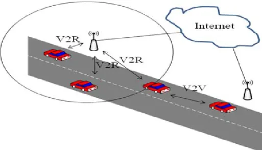
For entertainment applications, people can access to the Internet through devices known as roadsides units (RSUs), which are placed on the roadside and act as a communicative role between vehicles and the Internet. With Vehicle to RSU (V2R) Communication, operators can provide a variety of services like streaming TV, commercial advertisements or on-line games etc. Therefore, passengers in cars can turn on TV to enjoy a live basketball game simultaneously or surf on the Internet instead of having nothing to do during driving. Figure 1 shows brief VANETs environment.
Figure 1 : An illustration of vehicular network environment
1.1 VANETs
Vehicular Ad hoc Networks (VANETs) is one specialized case of Mobile Ad hoc Networks (MANETs). There are some characteristics of VANETs. First, unlike MANET whose nodes can move randomly, vehicles within VANETs must move along existing roads. In general condition, mobility paths of vehicles follow traffic signal. Besides, vehicles can be devised with GPS information so that most traffic information like traffic situation and navigation can be predicted. Second, speeds of vehicles are limited in common range and depend on their previous speed. Besides, vehicles do not accelerate or decelerate suddenly due to human nature driving behavior.
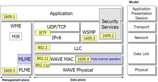
The Intelligent Transportation Systems (ITS) Committee of the IEEE Vehicular Technology Society (VTS) define IEEE P1609 draft in past years. IEEE P1609 contains four subjects for different purposes respectively. Figure 2 shows the stack model of four subjects in IEEE P1609. IEEE P1609.1 [2] specifies resource management in VANETs. It defines a set of commands to access memory page and defines relationships between resource and page. Then, Resource Manager
Application (RMA) can manage resource devices by those commands to access memory page. IEEE P1609.1 is associated with Application Layer in OSI model. Next, IEEE P1609.2 [3] specifies security issue in VANETs. It defines secure message formats and management process. The purpose of IEEE 1609.2 is to prevent a variety of network attack such as Eavesdropping, Spoofing, Alteration, and Replay attack. IEEE P1609.3 [4] specifies Transport Layer and Network Layer services and operations between RSUs and On-Board Units (OBUs). OBUs represent wireless communication devices in vehicle. It defines existing UDP packet, IPv6, LLC, WAVE short message (WSM) and its communication protocol WSMP. Generally, when applications want to communication with other devices in VANETs, it can decide to establish a WBSS or not. If yes, it can transmit packet through IPv6 formats on Service Channels or WSM formats on both type channels. Otherwise, it will be restrict to use WSM format to transmit data on Control Channel. Besides, IEEE P1609.3 also defines WSM formats and operations in WBSS from initiation to termination. Later we introduce lower layer in VANETs, which is more concerned with this thesis.
In 1999, the Federal Communications Commission (FCC) of the U.S allocated 75MHz bandwidth at 5.9 GHz to be used in V2V or V2R communications. The overall bandwidth is divided into seven frequency channels. One of seven channels is assigned as the Control Channel (CCH), which can be used to transmit safety messages or other high priority messages. The other six channels are assigned as Service Channels (SCHs) for non-safety message or other entertainment applications.
1.2 IEEE P1609.4/IEEE 802.11P MAC PROTOCOL
1.2.1 Multi-Channel Operation
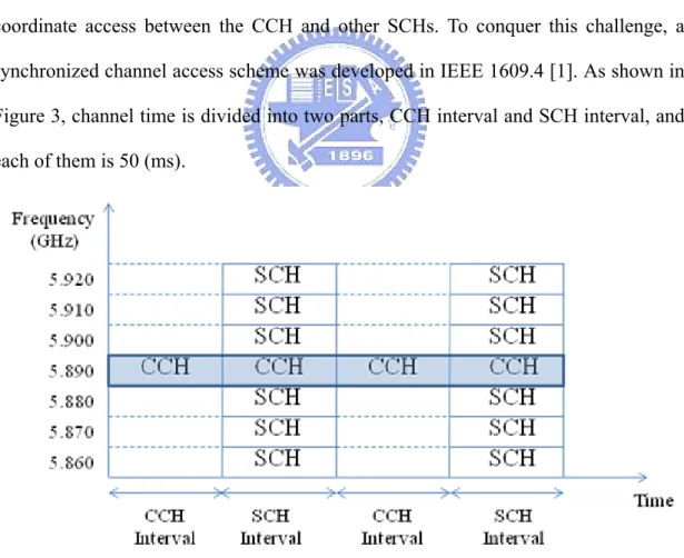
In VANETs, a challenge for a single interface device is how to efficiently coordinate access between the CCH and other SCHs. To conquer this challenge, a synchronized channel access scheme was developed in IEEE 1609.4 [1]. As shown in Figure 3, channel time is divided into two parts, CCH interval and SCH interval, and each of them is 50 (ms).
Figure 3 : Multi-channel operation in IEEE 1609
According to the scheme, all devices must switch to Control Channel during CCH intervals. In CCH intervals, safety messages and other high priority messages
can be transmitted in this period. During SCH intervals, a device can optionally switch to Service Channels if it wants to provide services or use services someone provided. In this way, it can ensure that all devices will stay on the same channel during CCH intervals so that they would not lose high priority messages on account of stay on different channels.
1.2.2 IEEE 802.11p MAC Protocol
The MAC layer operation in 802.11p [5] uses Enhance Distributed Channel Access (EDCA) mechanism, which is the same as the mechanism used in 802.11e. EDCA defines four different Access Categories (ACs) for different priorities, and all packets are classified into four of them. Each AC has different access parameters includes Arbitration Inter Frame Space (AIFS) and minimum Contention Windows (CWmin), maximum Contention Windows (CWmax). Packets with higher priority can
be assigned with smaller AIFS and smaller CW so that it wait for less backoff time to get more chance to transmit. EDCA is developed from DCF, and similarly based on CSMA/CA scheme. To eliminate the problem of hidden terminals, a RTS/CTS mechanism with Network Allocation Vector (NAV) can be put to use if packet size exceeds RTS threshold.
1.3 Motivation
As mentioned above, bandwidth requirements for most entertainment applications in VANETs are essential no matter it is used in watching streaming TV applications or on-line games, sufficient bandwidth is necessary to support QoS of services. However, unlike other wireless ad hoc networks, there are so many limitations to confine data transmission rate in VANETs.
For architecture issues, entertainment applications rely on V2R communications, so transmissions of RSUs will be the bottleneck especially when many vehicles connect to the same RSU. In addition, due to high mobility of vehicles and limited cover range of RSUs, the duration for a vehicle communicating with a certain RSU is extremely limited.
For transmission protocol issues, multi-channel operation and 802.11p MAC protocol in VANETs are previously discussed in 1.2. Because the main purpose of VANETs is to provide safety transportation system, reliable transmission of safety messages is necessary in this issue. For this reason, as shown as figure 3, 802.11p defines that time will be separated into CCH intervals and SCH intervals, and all of vehicles must switch to Control Channel during CCH interval. It can ensure that all vehicles will stay in the same channel so that vehicles will not miss high priority message. However, for throughput sensitive applications, there are two main drawbacks in current 802.11p protocol. Low channel utilization is one of the drawbacks and it is inadequate for most throughput sensitive applications. We can see that all Service Channels are unavailable during CCH intervals due to the reason that vehicles all stay in Control Channel, so the maximum Service Channel utilization can only reach half of total utilization. On the other hand, DCF is a contention based protocol, so all vehicles need to contend with each other to transmit data. To prevent collisions, it needs more time in the procedure to back off and exchange RTS, CTS messages before sending data. Those are overheads and decrease system throughput.
High mobility of vehicles and limited communication duration are constrained by vehicular environments. Hence, in this thesis, we focus on MAC protocol issues and propose a novel MAC protocol to increase throughput for throughput sensitive applications in V2R communications.
The remaining of this thesis is shown as follows. In chapter 2, we will introduce some related work about current studies about MAC protocol in VANETs. Then, our proposed MAC protocol will be discussed in chapter 3. The simulation results will be shown in chapter 4. Last, in chapter 5 will be conclusion and future work.
Chapter 2 Related Work
There have been a lot of modified MAC protocols proposed for some objectives in VANETs. Most of the research proposed a novel MAC protocol to enhance system throughput or degree packet lose rate, and some research focused on safety issues, they decreased delay time of safety messages or enhanced reliability. Due to some drawbacks about distributed structure, more and more centralized protocols have been offered to make system more efficient. For V2R communications, RSUs can be regarded as Base Station to manage whole devices. And for V2V communications, neighboring vehicles form a cluster, one of vehicles is defined as a cluster head to do the same thing as Base Station, and others are defined as cluster members. Then, there are some related work about this issue which will be introduced as follows.
In [7], the authors modified original 802.11p MAC protocol to enhance system throughput like our thesis. Figure 4 shows its channel access process. It is similar to 802.11p, the difference is that it designs part of CCH interval for coordinated purpose among vehicles so that vehicles do not need RTS/CTS process to avoid collision in SCH interval. That way, vehicles can transmit data directly without contention, and enhance throughput. However, in [7] they did not analyze optimal length of beacon period, and in this system, maximum SCH utilization was still half of entire time. This, for throughput sensitive applications, this MAC protocol still could not satisfy their requirements.
Figure 4 : Channel access process from [7]
For V2R communications, [8] proposed a MAC protocol allowing RSU centralized to allocate time slots to each vehicle. RSU received requests from vehicles and then assign time slots to them so that they could communicate without collision. However, it was designed for single channel environment and could not be used in existing multi-channel environment. Besides, no ad-hoc mode could run in this proposal. Last, vehicles still had to request allocation before sending safety messages, and it was not efficient for high priority messages.
In [9], the authors proposed a cooperative downloading MAC protocol to enhance reliability of packets. They assigned part of time intervals for relay node to retransmit, so if packets had been lost, it still had chance to resend and decrease packet lost rate. But the proposal did not enhance system throughput, and it was still not suitable for throughput sensitive applications.
In [10], it solved fairness problem. Because vehicles with different speeds have their different limited time to communicate with RSUs, such characteristics will lead to fairness problem in VANETs. The authors proposed a modified 802.11 DCF channel access scheme as a solution to the problem. The proposed scheme adjusts the
probability of transmission at a time slot for each node according to its speed.
For cluster-based structure, [11] proposed a complete protocol for V2V communication. In [11], how to form a cluster and how to communicate intra-cluster and inter-cluster would be implemented. And it also analyzed delay time for safety message among different clusters. Although the proposed MAC could efficiently practice centralized management with vehicles in a cluster, it would still base on assumption that each vehicle had two interfaces so that it could access two channels simultaneously. However, the assumption was excessively unnecessary with two interfaces.
Another cluster-based MAC protocol was proposed in [12], the authors integrated the approach of cluster centralized management and a contention-based way to forwarding data, and avoided inter-cluster interference. However, in this proposal, all data transmission always had to be passed through cluster head; that is, cluster head would be a bottleneck and decreased system throughput.
In [13], it proposed a Self-Organizing MAC protocol for distributed TDMA allocation in V2V communications. It used part of packet headers for exchanging time information across 1-hop and 2-hop neighbor vehicles. Hence, this protocol can mitigate overheads by avoiding explicit timing information exchange.
Judging from above, all studies including draft 802.11p suppose that all vehicles have one interface except [11]. So we consider that it is not necessary to devise more than one interface in a vehicle. Hence, we also assume all vehicles are devised with one interface which can switch among multiple channels. Besides, due to efficiency of centralization management, [8], [11], and [12] adopt centralization structure protocol. Here we focus on RSU existing environment, so we also develop centralization structure protocol via RSU so that we can get more efficiency compared with distributed architecture.
Chapter 3 The Proposed MAC
Protocol
In this chapter, a novel MAC protocol will be introduced in detail. In our work, we only consider R2V environment, which means we suppose there are several RSUs placed in the road at every fixed interval, and all vehicles can be associated with specific RSU. Another assumption is each RSU has two interfaces, one always associates with Control Channel, and the other can associate with any Service Channel. Because RSUs act as a gateway and offer vehicles to link to Internet, it will be a bottleneck. Therefore, we suppose the assumption that each RSU has two interfaces will be reasonable. In addition, each vehicle in our work has only one interface and can switch to Control Channel or other Service Channels depending on its requirements. We assume vehicles are mounted with GPS devices so that they can get their positions via GPS.
3.1 Control Channel Access Structure of Our Proposed
MAC
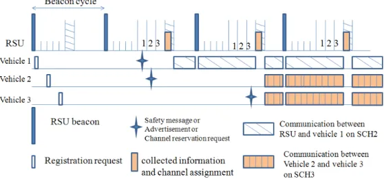
Figure 5 illustrates the detailed control channel access structure of our proposed MAC. The system time is segmented into Beacon cycles. As shown in the figure, the length of each Beacon cycle is Ct. Each Beacon cycle consists of registration period,
specific period and remainder time. Registration period contains m registration slots for vehicles registration purpose, and specific period contains n+1 specific slots for vehicles sending safety messages or bandwidth reservation request purpose. Here n is a variable which means current registered vehicle numbers, and the last specific slot is
for RSU. Parameter tr is the time length of registration slot and ts is the time length of
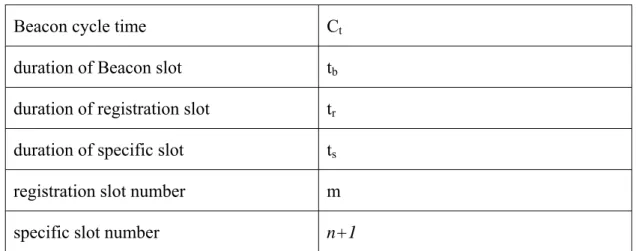
specific slot. In the channel access structure, each Beacon cycle starts with a Beacon sent by RSU. Table 1 shows parameters, and later we will introduce more about each function of our proposed MAC.
Figure 5 : Control channel access structure of our proposed MAC
Table 1 : Parameter settings in our proposed MAC protocol Beacon cycle time Ct
duration of Beacon slot tb
duration of registration slot tr
duration of specific slot ts
registration slot number m specific slot number n+1
3.2 Registration
In our research, RSUs periodically broadcast Beacons at every Ct interval on
Control Channel. Here we suppose it is a RSU-existing environment, so if vehicles do not receive any Beacon, their antennas would always stay at Control Channel so that vehicles would not miss information of RSUs. As the vehicles enter RSU’s coverage range, it will receive Beacon and starts its Beacon cycles. The packet of Beacon contain much information, such as RSU’s ID, Beacon cycle time, registration slot numbers m, IDs of registered vehicles and their own respective slot start time and end time and their registration duration. Vehicle registering to RSU will get its own specific slot to send safety message or bandwidth request message.
When a vehicle receives Beacon, first it will check whether this Beacon contains its own specific slot or not. If yes, it means that the vehicle had successfully registered before and it need not register again. If not, the vehicle will randomly select a registration slot to send registration packet to RSU. The registration packet contains information like a vehicle’s ID, location, speed. Then, RSU adds the vehicle to its member list and estimates registration duration by the vehicle’s location and speed. If registration duration expires, RSU will remove the vehicle from its member list. At that time if the vehicle does not exit and discover the Beacon without its specific slot, it will register again.
If there are more than one vehicle sending registration packets in the same registration slot, they will collide. Those vehicles will not get their specific slot from next Beacon, and then they will register one more time. So here we estimate the probability of registration failure.
Suppose the average number of arriving vehicles in a Beacon cycle time is x, and we only consider registration failure happening as a result of collision in registration
slots. The registration failure probability P can be expressed as follows.
1 !
!
!
! represents registration success probability that all vehicles select
different registration slots. Then we calculate the expected value of registration times that a vehicle needs to send. First, we suppose to r is the ratio of vehicles which can register successfully in a Beacon cycle which x vehicles arrives. So for those x vehicles, average registration times N can be expressed as followed:
· · 1 · 1 · · 2 · 1 · · 3
2 1 · 3 1 · 1 1
Then, we calculate the ratio r which represents the ratio of vehicles which can register successfully in a Beacon cycle which x vehicles arrives. We can get the registration success probability for one specific vehicle as followed:
1
And then the ration r can be expressed as (2) so that we can estimate average registration times N in (1).
Considering real situation, suppose we set Beacon cycle time as 100 (ms), that is, vehicles can only move about 1.66 (m) in a Beacon cycle time when average speed is 60 (km/hr). So in a Beacon cycle there can not be more than 1 vehicle arriving in one lane. Therefore, if a road has three lanes (a=3), and we set registration slot number m as 10, the maximum registration failure probability P is only 0.28 and the expected value of registration times N is about 1.23.
After registration process, each vehicle will have its own specific slot. Here we discuss upper bound of registered vehicles number. Suppose the number of registration slot is 10 and duration of registration slot and specific slot are both 0.5 (ms), so each Beacon cycle (100 ms) can contain 190 specific slots, namely available registered number is 190 at most in a RSU’s coverage. Now we consider a heavy traffic situation, and suppose the length of vehicles is about 5 (m), average gap between vehicles is 15 (m). So in a 4 lanes road, the maximum vehicle number could not be more than 100 under a RSU’s transmission range which supposed to be 500 (m). This number 100 is less than available registered number 190 much more. The result indicates that we set Beacon cycle time 100 (ms) can be adequate for real road environment. In cast of overflow in some special situations, we only need to extend Beacon cycle time to accommodate more vehicles.
3.3 Communication
After registration, each vehicle has its own specific slot to use. In its own specific slot, all the other vehicles can not send messages, data or any other information in Control Channel so that each vehicle can directly send packet without the process to avoid collision. As shown in figure 5, if n vehicles have registered, there will be n+1 specific slot in a Beacon cycle, and the last one is for RSU to use.
send a channel reservation request to RSU to get its reservation time first. After receiving the request from vehicles, RSU will handle bandwidth reservation and then broadcast channel assignment message to all vehicles in RSU’s specific slot. In this part, if there are more than one vehicle want to use same bandwidth resource, RSUs can allocate bandwidth resource by running a specific algorithm, such as common FCFS, weighted round-robin, or other special resource management algorithms. In this thesis, we suppose RSUs adopt FCFS for allocating bandwidth resource, i.e., vehicles which requested earlier will get the channel reservation. Obviously, all vehicles must stay in Control Channel during Beacon slot interval and RSU’s specific slot interval, or vehicles will miss Beacon message or channel assignment message. Except for these two intervals, all other time vehicles can switch to Service Channel for other entertainment services. It is the main difference between our proposed MAC and 802.11p. Also, this is the key point that the system throughput of our proposed MAC outperforms 802.11p.
The following is an example of our proposed MAC. As shown in figure 6, if three vehicles enter a RSU’s transmission range simultaneously. They will receive Beacon and start their Beacon cycle. Here we set the number of registration slot is five, and three vehicles select the 1st, 3rd, and 5th registration slots respectively so that they will not collide and all registration will succeed. At next Beacon cycle, three vehicles will discover their specific slot information in this Beacon message and realize they had registered successfully. Suppose passengers in vehicle 1 want to enjoy streaming TV service, so vehicle 1 sends channel reservation request to RSU at its own specific slot. Meanwhile, vehicle 2 wants to offer service, so vehicles 2 also send advertisement to RSU at its own specific slot.
Figure 6 : An example for our proposed MAC
Then RSU collects all messages in this Beacon cycle and then broadcasts collected information and channel assignment to vehicles. Collected information contains safety message and advertisement, and channel assignment message is the result after some resource management algorithms or admission control. Back to figure 6, vehicle 1 receives RSU’s channel assignment at RSU’s specific slot, so vehicle 1 will switch to Service Channel 2 at the reservation start time according to channel assignment message. And then it starts to communicate with the Internet server via RSU till the end of reservation. Especially, vehicle 1 needs to return to Control Channel at Beacon interval and RSU’s specific slot interval to receive necessary information. As to remainder time, vehicle 1 can switch to Service Channel for its transmission.
Within the same time of RSU’s specific slot, vehicle 3 receives RSU’s collected information which contains vehicle 2’s advertisement message. Afterword, suppose vehicle 3 has interest in vehicle 2’s service, vehicle 3 will send channel reservation request to RSU in its own specific slot. Next, RSU will allocate a channel for a period
to those two vehicles and then broadcasts channel assignment information to inform all vehicles in RSU’s specific slot. After vehicle 2, vehicle 3 receiving channel assignment information, they will start their communication at Service Channel 3 which RSU assigned.
By the way, because channel assignment is central-managed by RSU, there must not be more than one communication pair in the same assignment duration. This is, vehicles can communicate with each other in their assignment duration without interference or collision, so they can directly send data and wait for ACK without RTS/CTS handshake process. That will be another factor to enhance system throughput.
3.4 Safety Issue
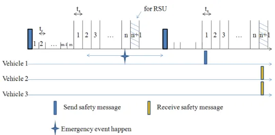
Safety issue has always been a key point in VANETs development. For this reason, 802.11p designs half of synchronization interval to be CCH interval and in this interval all vehicles must return to Control Channel to learn about whether there is an important information or not. If there has been emergency event like car accident, vehicles can exchange safety information during CCH interval.
In our proposed MAC, when an emergency event happened, vehicle whose transmission is idle will send safety message to RSU in their specific slot directly. If vehicle’s transmission is busy, the vehicle will temporarily switch to Control Channel during its specific slot period to send safety message to RSU and then return to Service Channel to continue its original service. So when RSUs collect safety information, RSUs will broadcast collected information in the RSU’s specific slot. Meanwhile, all vehicles will receive safety message because they must return to Control Channel during RSU’s specific slot. In this way, it can ensure our proposed
MAC still satisfies function of safety service.
Then we compare the performance of our proposed MAC protocol and 802.11p. In the following, the delay time of safety messages will be analyzed. We define the delay time starts from the moment the accident happened to the time that neighboring vehicles all receive this safety message.
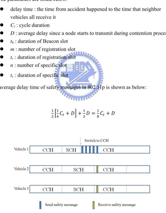
The parameters are listed below.
z delay time : the time from accident happened to the time that neighbor vehicles all receive it
z Ct : cycle duration
z D : average delay since a node starts to transmit during contention process z tb : duration of Beacon slot
z m : number of registration slot z tr : duration of registration slot
z n : number of specific slot z ts : duration of specific slot
Average delay time of safety messages in 802.11p is shown as below:
(3)
First part of left equation in (3) indicates that accident happened at SCH interval. As shown as figure 7, if vehicle 1 has some emergency events at that time, so it switches to Control Channel and broadcasts safety messages constantly; however, vehicle 2 and 3 which stay in Service Channel will miss the message and could receive safety message at next CCH interval. Hence, the expected value of waiting time is half of CCH interval time, namely, quarter of Ct. Besides, D is average delay
time when a node starts to transmit during contention process or back-off process. The second part of the left equation indicates that a vehicle which has accident wants to send safety message at CCH interval. Because at CCH interval all vehicles must stay in Control Channel, the delay time of safety message is only D. Usually, Ct is
supposed to 100 (ms) and D is much less than Ct , so average delay time of 802.11p is
approximately 12.5 (ms).
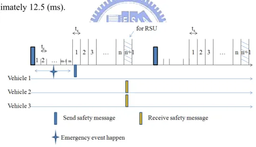
Figure 8 : Vehicles’ channel states of emergency event in our proposed MAC
Similarly, we discuss average delay time in two cases in our proposed MAC. First, as shown in figure 8, if emergency event happened before vehicle’s own specific slot, this accidental vehicle could send safety message in its specific slot and then other vehicles could be informed in RSU’s specific slot. In this case, average delay time of safety message can be expressed as (4):
· ·
· · · (4)
The coefficient · · indicates the probability that emergency event happened before vehicle’s own specific slot, and later half part indicates expected value of delay time from emergency event happened to RSU’s specific slot.
Figure 9 : Vehicles’ channel states of emergency event in our proposed MAC
Second, as shown in figure 9, if emergency event happened after vehicle’s own specific slot in the same Beacon cycle, this accidental vehicle only can send safety message in next Beacon cycle during its specific slot and then other vehicles could be informed in next Beacon cycle during RSU’s specific slot. In this case, average delay time of safety message is expressed as (5):
· ·
The coefficient · · indicates the probability that emergency event happened after vehicle’s own specific slot, and later half part indicates expected value of delay time from emergency event happened to next RSU’s specific slot.
After calculating the sum of (4) and (5), we can get average delay time as (6):
· (6)
Because · is less than Ct more, if Ct is set as 100 (ms), the average delay
time is about 50 (ms) in our proposed MAC. Even in heavy traffic situation discussed in previous registration phase, if there are 100 vehicles under a RSU’s transmission range, the average delay time is about 75 (ms). Although delay time in our proposed MAC is longer, it still does not influence safety. Studies shows maximum allowable delay of safety message is 100~150 milliseconds and driver’s perception time is 500~1000 milliseconds. So no matter it is 802.11p or our proposed MAC, they all satisfy safety requirements.
3.5 Throughput analysis
3.5.1 Throughput Analysis for 802.11p
In IEEE 802.11p, the analytical model developed by G.Bianchi [14] is adopted here. Follows are the parameters in this analysis:
Table 2 : Parameter settings in analysis
τ the probability that a device will transmit a packet at an arbitrarily chosen slot time
P the probability of a packet being collided
Ptr the probability of at least one device transmits at the considered slot
Ps the probability a transmission is successful
pSlotTime average time that a slot being empty
Ts average time used for successful transmission
Tc average time wasted by a packet collision
S1609 saturation throughput of IEEE 1609/802.11p
According to bidimensional Markovian model in [14], the probability τ that a device will transmit a packet at an arbitrarily chosen slot time and the probability P of a packet being collided are shown as below:
∑ (7)
1 1 (8)
Then, we can calculate the probability at least one device transmits at the considered slot according to (7) and (8); obviously, the probability Ptr is total
probability 1 subtract the probability that all n devices do not transmit at the considered slot. It can be expressed as follow:
Next, the probability that a transmission is successful indicates only one device transmits at considered slot and other n-1 devices do not transmit at the same slot. The probability Ps can be expressed as (10):
1
110
Based on above expressions, the saturation throughput of DCF MAC is given by:
(11)
The coefficient 1/2 in (11) indicates SCH interval is only half of the channel time. The numerator represents transmission time for sending a data, and the denominator represents average time wasted for a transmission. The unit of saturation throughput is a percentage which means maximum useful time for transmitting a data in a reservation. Besides, let , , , and denote the time to transmit an RTS, CTS, DATA , and ACK. So Ts and Tc with RTS/CTS are shown as follows.
12
13
Ts and Tc without RTS/CTS are shown as follows.
15
3.5.2 Throughput Analysis for our proposed MAC
In our proposed MAC, the saturation throughput can be expressed as:
· · (16)
Similarly as analysis of 802.11p, the coefficient in (16) indicates available transmission time ratio during a Beacon cycle. As discussed in previous chapter, vehicles can switch to Service Channels to transmit data all the time except Beacon slot interval ( ) and RSU’s specific slot interval ( ).
That is the maximum number of packet can be transmitted in a reservation. It is expressed as (17). The numerator is reservation time and the denominator indicates the total duration to transmit a packet.
(17)
Above saturation throughput analysis for both protocols can be extended to multiple SCHs environment. However, because RSUs only have one interface for SCHs, saturation throughput of R2V communications will not increase when service channel increase. In fact, other bandwidth can be used by V2V communications.
Chapter 4 Performance Evaluation
In this chapter, performance of our proposed MAC protocol and original 802.11p MAC are evaluated by C/C++ and the results will be compared and discussed later.
4.1 Simulation Environment
The simulation environment is a quadratic road system as shown in figure 7. There are two lanes and each length of the edge is 0.5 (Km). Four RSUs are placed in the corner of square and their transmission range are 250 (m) so that four RSUs can cover all vehicular environment. And it is a closed system, no entrances or exits exist in the vehicular environment.
At the beginning of simulation, all vehicles are placed in the quadratic road system evenly, and move in anticlockwise direction. Speeds of vehicles are 60Km/hr and 80Km/hr respectively in outside lane and inside lane. Then, all vehicles request for streaming service through RSUs from the Internet. When a vehicle exits from its original RSU and enters the next RSU’s coverage range, it will request again to keep streaming service running. The bit rate of stream is set from 120Kbps to 440Kbps in different simulated situations and packet size of data is 1024 bytes. The download scheduling algorithm in RSU for 802.11p is round-robin for all vehicles, and FCFS for our proposed MAC. Namely, in our proposed MAC, RSU will finish a demand of the current vehicle and then serve the others. The reason is that 802.11p is a distributed protocol so that it can’t serve vehicles centralizedly. Next, in this simulation, in order to make it brief, we use two channels to transmit. One channel is for CCH and the other is for SCH. It can be easier to extend to multiple service channels in vehicular network environment.
The parameters used in the simulation are listed in table 3. Table 4 and 5 are EDCA parameter in 802.11p, and to calculate CWmin and CWmax the values aCWmin =
15 and aCWmax = 1023 have to be used. Here we adopt AC1 for streaming packets
Table 3 : Simulation parameters Simulation time 60 seconds
Vehicle density 16~28 vehicle/km/lane Transmission range 250 meters
Data rate 6 Mbps Packet size 1024 bytes Stream bit rate 120~440 Kbps Cycle time 100 ms
Slot interval (proposed MAC) 0.5 ms Registration slot number 10
Table 4: EDCA parameter set used on the CCH AC aCWmin aCWmax AIFS
0 aCWmin aCWmax 9
1 (aCWmin+1)/2-1 aCWmin 6
2 (aCWmin+1)/4-1 (aCWmin+1)/2-1 3
3 (aCWmin+1)/4-1 (aCWmin+1)/2-1 2
Table 5 : EDCA parameter set on the SCH
AC aCWmin aCWmax AIFS
0 aCWmin aCWmax 9
1 aCWmin aCWmax 6
2 (aCWmin+1)/2-1 aCWmin 3
4.2 Simulation Results
The performance is evaluated by throughput, receipt ratio, registration times, and delay of safety messages. We set different stream bit rate and vehicle density in both protocols to compare performances.
Figure 8 shows the saturated transmission rate of RSU versus simulation time. The saturated transmission rate means maximum available data rate that a device can send or receive in our proposed MAC and original 802.11p. We can see that simulation results are close to theoretical values, and our performance is twice more than 802.11p because our proposed MAC fully utilizes service channel; besides, vehicles need not send RTS/CTS to avoid collision. The gaps between theoretical results and simulated results in our proposed MAC are caused by mobility of vehicles and channel switch. For example, vehicles which move out of RSU’s transmission range will miss transmitting packet and vehicles which return to Control channel during RSU’s specific slot will lose transmitting packet, too. With regard to 802.11p, the gap is also caused by mobility of vehicles. In addition, we suppose random back off numbers in theoretical analysis are always the minimum number, so the theoretical results are optimal results, and that is the another reason causing the gap.
Figure 11 : Saturated transmission rate of RSUs versus simulation time
Figure 12 : Average throughput versus vehicle ID
Average throughput of each vehicle is shown in figure 9. In this simulation, vehicle density is 20 (vehicles/km/lane) and streaming bit rate is set as 280 (Kbps). It appears that average throughput of our proposed MAC almost meets demand of bit rate and outperforms 802.11p a lot. Similarly, figure 10 shows receipt ratio of demand. When the request of streaming bit rate is 280 Kbps, our proposed MAC can receive
90% and original 802.11p only obtains 40% of total data amount. The phenomenon of uneven performances among different vehicles is caused by scheduling algorithm, which common FCFS is used in our proposed MAC in this simulation. In some cases, if a vehicle enters a high-load area of RSU, it might not get chance to satisfy its requirements before it exits. That is why the performances of some vehicles are poorer. However, the difference of them is within 5%.
Figure 13 : Receipt ratio versus vehicle ID
Next, figure 11 and figure 12 show throughput and receipt ratio versus request streaming bandwidth. In this simulation, vehicle density is 20 (vehicles/km/lane), and each vehicle request 120~440 (Kbps) stream service. Obviously, our proposed MAC could offer more than 250 (Kbps) data rate, so receive ratio of 120 and 200 (Kbps) stream could achieve near 100%. However, in 802.11p, maximum throughput of each vehicle couldn’t get more than 120 (Kbps) and does not satisfy for all situations. In fact, most streaming video applications need more than 100 (Kbps) bandwidth. High-quality videos even need 200 or 300 (Kbps) to support QoS. Therefore, in
current 802.11p protocol, in urban area where there are many vehicles, it is more difficult to offer entertainment service to most vehicles, and modifying 802.11p to enhance throughput requirement is necessary.
Figure 14 : Average throughput versus streaming bandwidth
Now, we discuss the relationship between vehicle density and the performance. Figure 13 shows average throughput in different vehicle density. In this simulation, streaming bit rate is set as 360 (Kbps). As vehicle density increases, the decrease in throughput is reasonable. It is because more vehicles share the total resources. Figure 14 is corresponding receive ratio results, and similarly, our proposed MAC is better than 802.11p. Regardless of vehicle density, performance of our proposed MAC is about twice better than the original 802.11p protocol.
Figure 17 : Receipt ratio versus vehicle density
In the following, we discuss how many times vehicles need to register to a new RSU till success. In figure 14, the index of y-axis indicates average registration times when a vehicle meets its n-th RSU. This is, the RSU which vehicle meets first is the vehicle’s first RSU, and then after the vehicle exits, the vehicle will meet its second RSU. At the beginning of simulation, all vehicles have not yet registered to RSUs, so they need to content with all the others to register successfully. As a result, the average number is higher than later RSUs which they would meet. As vehicle density increases, registration times would increase as well. Thereafter, when vehicles meet their second RSU, they need not content with so many vehicles for registration. When a vehicle meets its first and second RSU, other vehicles have not all finished their first registration, it can be regarded as initial state. After initial state, all vehicles have finished their first registration, so new coming vehicles just need to contend with other new coming vehicles and it will become a stable situation. In figure 18, we can observe that vehicles only need to register for approximately one time for the third
RSU and fourth RSU which can be regarded as stable state above. The results are consistent with our analysis in previous chapter. In our simulated environment, there can not be more than two vehicles entering a RSU’ range simultaneously in a cycle time. Here we set registration slots as 10 which is enough to handle in most cases, so the factor of vehicle density does not influence the result.
Figure 18 : Average registration times versus vehicle density
In figure 19, average delay of safety messages is shown as follow. This period is defined from the time an accident happened to the time all neighboring vehicles receive messages successfully. Simulation results show delay time in our proposed MAC is about 50 (ms) in average traffic situation and delay time in 802.11p is approximately 10 (ms). The value of 802.11p is less because the original protocol aims at reducing accidents, and that is why half of cycle time would be designed as CCH for high priority messages. As our previous analysis, average delay of safety messages is direct proportion with vehicle density, but vehicle density in our simulation is not heavy so that it does not reflect on the result well. The result of delay time is about half of cycle time, which is 50 (ms). However, 50 (ms) of delay time is under maximum allowable latency of safety messages (100 ms to 150 ms), which
shows the pursuit of safety would not be sacrificed to enhance throughput in our proposed MAC.
Chapter 5 Conclusion and Future
Work
In this thesis, we propose a novel MAC protocol to enhance system throughput. The main improvement is that we enhance channel utilization compared with original 802.11p whose channel utilization is half at best. Then, we discuss registration process, channel reservation process, transmission data or safety message process, and analysis performance such as registration failure probability, delay time of safety message, and throughput. In our simulation, we prove that our throughput outperforms IEEE 802.11p. Moreover, compared in different situations, throughput and data receipt ratio in our proposed MAC are better. Besides, we also show average delay time of safety message in these two protocols. Results show the performance of 802.11p is better, but both simulation results are in accordance with our theoretical analysis and both are under maximum allowable latency.
In this thesis, we only consider V2R environment, i.e., there must be RSUs equipped on the road. However, it is impossible to equip RSUs everywhere, especially in rural area. In that case, one of the vehicles has to act as cluster head and manage all the registration and reservation. Therefore, how to coordinate between RSU-based and cluster-based environment will be a future work. Furthermore, because our proposed MAC is a centralized structure, scheduling algorithm and admission control will be critical issues. How to schedule different flows or make admission decision according to the characteristic of VANETs applications can also be future work, too.
References
[1] IEEE P1609.1, “Wireless Access in Vehicular Environments (WAVE) Resource Manager,” Draft Standard, 2007.
[2] IEEE P1609.2, “Wireless Access in Vehicular Environments (WAVE)
Security Services for Applications and Management Messages,” Draft Standard, 2007.
[3] IEEE P1609.3, “Wireless Access in Vehicular Environments (WAVE) Networking Services,” Draft Standard, 2007.
[4] IEEE P1609.4, “Wireless Access in Vehicular Environments (WAVE) Multi-Channel Operation,” Draft Standard, 2007.
[5] IEEE Standard for Information technology , “Part 11: Wireless Medium Access Control (MAC) and Physical Layer (PHY) specifications: Amendment 3: Wireless Access in Vehicular Environments (WAVE),” IEEE Draft
Amendment P802.11p/D1.0, Feb, 2006.
[6] Vehicle Safety Communications Project, Final Report, DOT HS 810 591, April, 2006.
[7] Zang Y, Stibor L, Walke B, Reumerman HJ, Barroso, “A Novel MAC Protocol for Throughput Sensitive Applications in Vehicular Environments,” IEEE VTC, 2007,pp. 2580–2584.
[8] Biplab S, “A MAC Protocol for Vehicle to Roadside Networks,” IEEE ICC, 2008.
[9] Jin Z, Qian Z, Weijia J, “A Novel MAC Protocol for Cooperative Downloading in Vehicular Networks,” IEEE GLOBECOM, 2007.
[10] Ehsan K, Farid A, “A Modified 802.11-Base MAC Scheme to Assure Fair Access for Vehicle-to-Roadside Communication,” Computer Communication, VOL. 31,
July, 2008, pp. 2898-2906.
[11] Hang S, Xi Z, “Clustering-Based Multichannel MAC Protocols for QoS Provisionings Over Vehicular Ad Hoc Networks, ” IEEE JVT, VOL. 56, NOVEMBER, 2007, pp. 3309-3323.
[12] Zaydoun Y, “Media Access Technique for Cluster-Based Vehicular Ad Hoc Networks,” IEEE VTC, 2008.
[13] Fan Y, Subir B, “A Self-Organizing MAC Protocol for DSRC based Vehicular Ad Hoc Networks,” IEEE ICDCSW, 2007.
[14] Giuseppe B, “Performance Analysis of IEEE 802.11 Distributed Coordination Function,” IEEE JSAC, vol. 18, March, 2000.
![Figure 4 : Channel access process from [7]](https://thumb-ap.123doks.com/thumbv2/9libinfo/8737808.203645/17.892.200.683.107.449/figure-channel-access-process.webp)